Again, thank you for your help! It seems that my audience is growing

The power supply in these scopes runs at about 30-40kHz so it it may be possible for it to be audible if it runs lower than that.
I looked at the service manual and found out that it runs at approximately at 18kHz, so it's just below the upper end of the audible spectrum.
Is that damage on the carbon element of the pot? If it is you can always slightly bend the wiper contacts so that they don't slide across the bad area. If the carbon element has a crack in it there will be no conductivity between the far end contacts of the pot.
Yes it is. I opened it again and fixed it the way you said.
It's probably a better idea to just replace the caps than investing in an ESR meter. The caps can also be replaced as a last resort if everything else seems to work as it should.
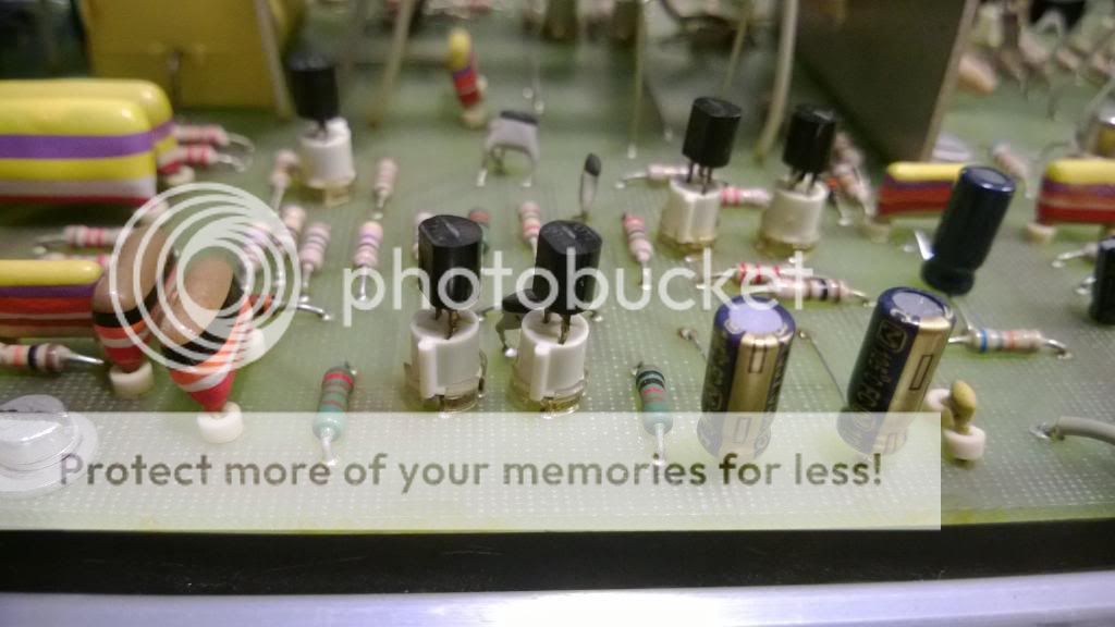
I replaced all electrolytic caps on all boards. Sadly the board is not so colourfull than before with the new black caps. The trace still does not appear. Now at least we know that the caps are fine and not causing the problem

I would make sure that the semiconductors are making contact in the sockets. Often you only have to juggle the transistor to clean off the oxide. Seems you are making good progress, good luck.
Thank you! I moved all transistors in the sockets a bit. Still no trace.
I always unplug an plug transistors in sockets a few times. I had a Tek 7704 that had a trace problem that was only caused by a transistor/socket problem.
Your psu values look good. I always test caps on DC leakage, capacitance and DF with one leg desoldered.I have designed and build several ESR meters, I have a professional ESR meter ans can measure it in other ways. And I almost never measure ESR in repairs. Only if it involves a SMPS, and I never measure it in circuit. Done a lot of tests comparing in situ and desoldered caps and they differ much to much. Bad ones can look good so that is allready a no-no for me.
The best check is measuring ripple current and DF
http://www.pa4tim.nl/?p=3775 about ESR
http://www.pa4tim.nl/?p=1728 build an ESR meter with adjustable frequency and able to measure as low as 100 nF caps
http://www.pa4tim.nl/?p=1385 DC leakage and testing
Measure C with a LCR meter, most multimeters use DC and are more then 100% wrong if caps are bad. The high ESR makes the meter think (RC time) the capacitance is still good,
I repaired a few Philips scopes but older models (including two 1 GHz sample scopes) most problems: switches and leaking high voltage cascade caps.
The old blue Philips caps from the 70's/80's are not the greatest in my opinion. From all my gear I only had a Tek SA that needed all caps replaced, In a HP LCR meter al caps smaller as 10 uF were bad but for the rest no problems, except for Philips gear . There I hade to replace many caps, but that are most silverface models, so older then your scope.
Wow, you have a very nice and usefull website. Thank you for sharing your research. It's too bad that it wasn't on the first pages when I googled for ESR. If i had not ordered the new caps before you wrote, I maybe would have ordered the parts for building an ESR meter. Perhaps that will be a future project.
I use a pipe-socket/rohrschluessel. http://upload.wikimedia.org/wikipedia/commons/7/7a/Rohrschluessel.jpg
The best way to test transistors is measuring the voltage in situ. Vbe must be around 0.6-0.7V or 0.35 for germanium. And with a scope you see amplification or switching. And if voltages are good, the transisator is working.
The pipe-socket/rohrschluessel looks like a usefull tool, I have to look for it in my local hardwarestore. Do you also say "Rohrschluessel" in the Netherlands or did you translated it for me into german?
Nice documented restauration. You have a good eye for detail.
Thank you very much!
The white Mini-Latch style connectors used in newer Philips scope models are worth exercising as part of a restoration. They also tend to cause weird problems simply due to making poor contact.
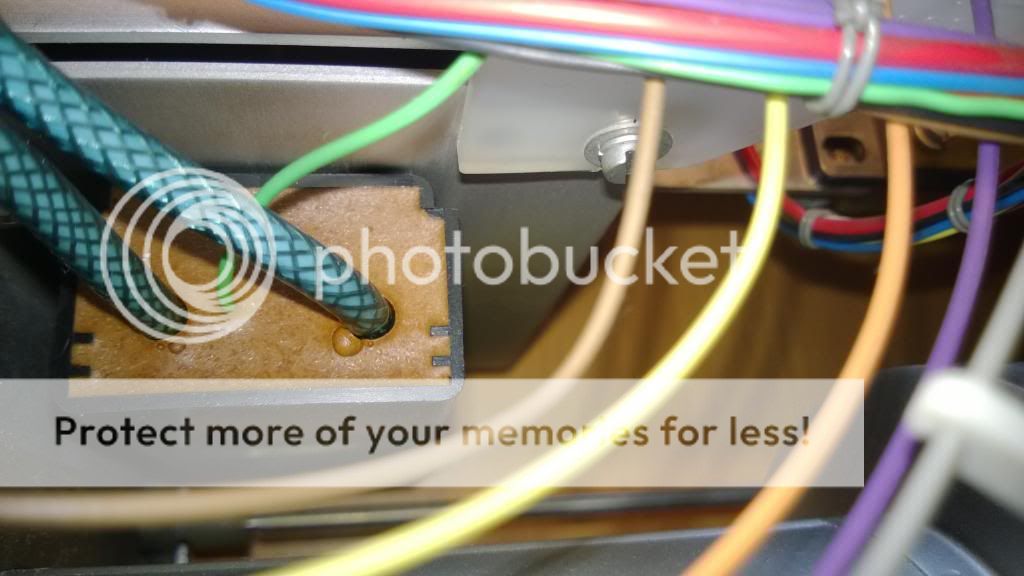
I think my scope does not have these sockets, because there were no latches on them. I only found this three different types:

Orange.
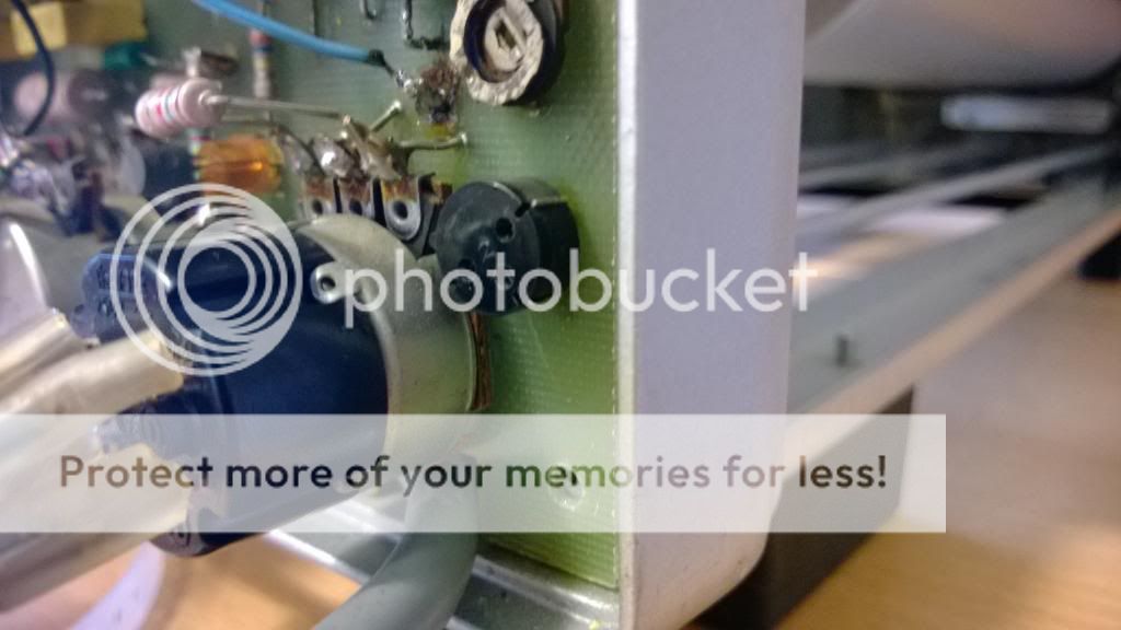
Black.
And white.
So I think, if all caps are okay, all testpoints in the circuit are ok and the voltage levels on all the low voltage rails are high enough, the problem has to do with the high voltage circuits.
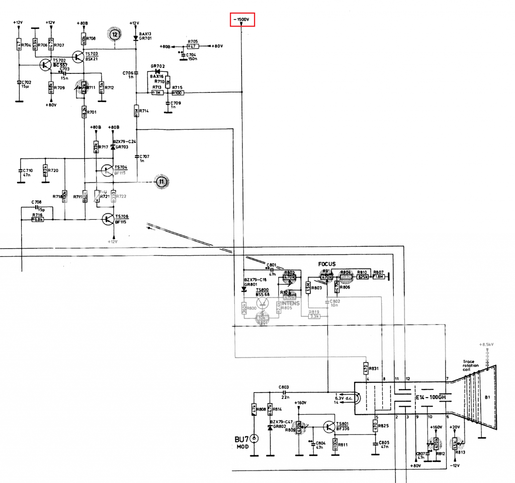
I think either the acceleration voltage is too low or the blanking voltage is to high when it shouldn't blank.
But I assume that the acceleration voltage is too low because the waveform I measured of the circuit which drives the blanking was like it is displayed in the schematics.
Here are the parts of the schematics that have to do with the -1500V rail:
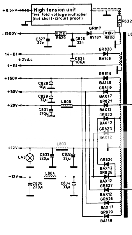
I could not find any shorted caps or diodes in the circuits. Maybe the five fold voltage multiplier is damaged? The problem is that I cannot check the single components of the multiplier because its in a box filled with some (isolation?) material:
So I thought I could maybe hook it up to the 12V squarewave of the transformer and measure the output disconnected from the crt with my scope. Is that a bad idea? I would do it like this:
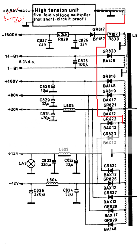
Does anybody know what ciruit could be inside this "black-box"? Could it be an Cockcroft-Walton Multiplier like Dave explained in that video: ?
http://youtu.be/ep3D_LC2UzUI have one last question. Do I have to care about x-Rays when the scope is turned on and the body housing is open? The CRT is partially covered with metal: