This is a bit of a long post, but by way of resurrecting this thread with an update.....
It doesn't seem like nearly a year since I looked at this 'scope, probably because it has been quite a busy one in which a much larger "spare time project" has sucked in almost
all of my spare time and effectively left none, or very little, for electronics.
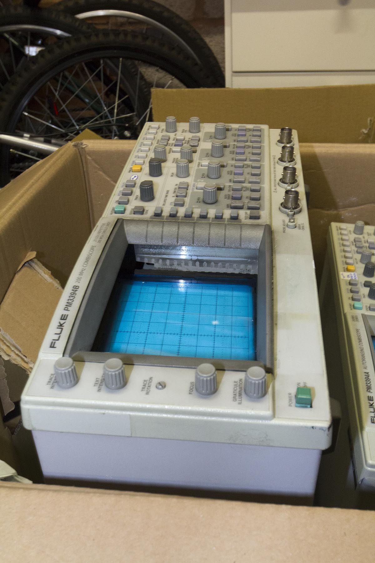
However I was spurred on to get this on the bench again following the opportunity to pick up two more of the Phillips Combiscopes - a 3394B which I have coveted for the bench for a while and a 3394A. Of course I also had the 3380B digitiser card that High Voltage sent me so I now have plenty of opportunity to narrow faults down by swapping components.
The "A" was said to be working, but making funny noises when adjusting the trigger level and the B apparently would not to boot, but I always like a challenge.
Sadly the "B" suffered the same problem as the 3380B High Voltage bought, though it was not quite as damaged. On opening the box the sight of lots of loose polystyrene chips greeted me along with two 'scopes that had barely any other protection (a bit of bubble wrap stuffed over the front panels). The CRT of the "B" had disappeared into the case.

As usual all pics are links to a larger version.
Fearing the worst I was actually pleasantly surprised to find that the CRT neck was not broken but the chassis had split
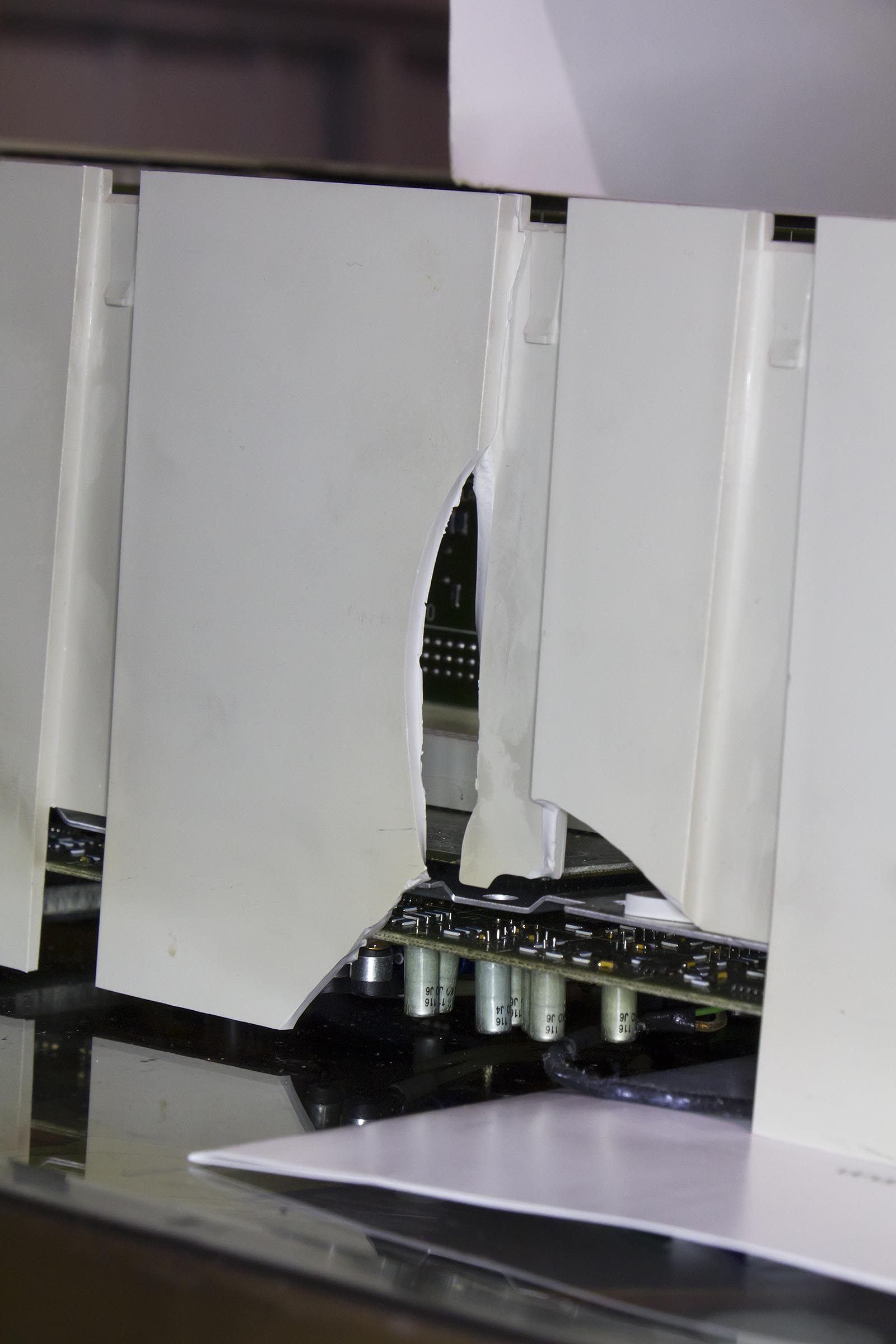
and the CRT mounting was completely smashed allowing the CRT to move back a couple of inches.
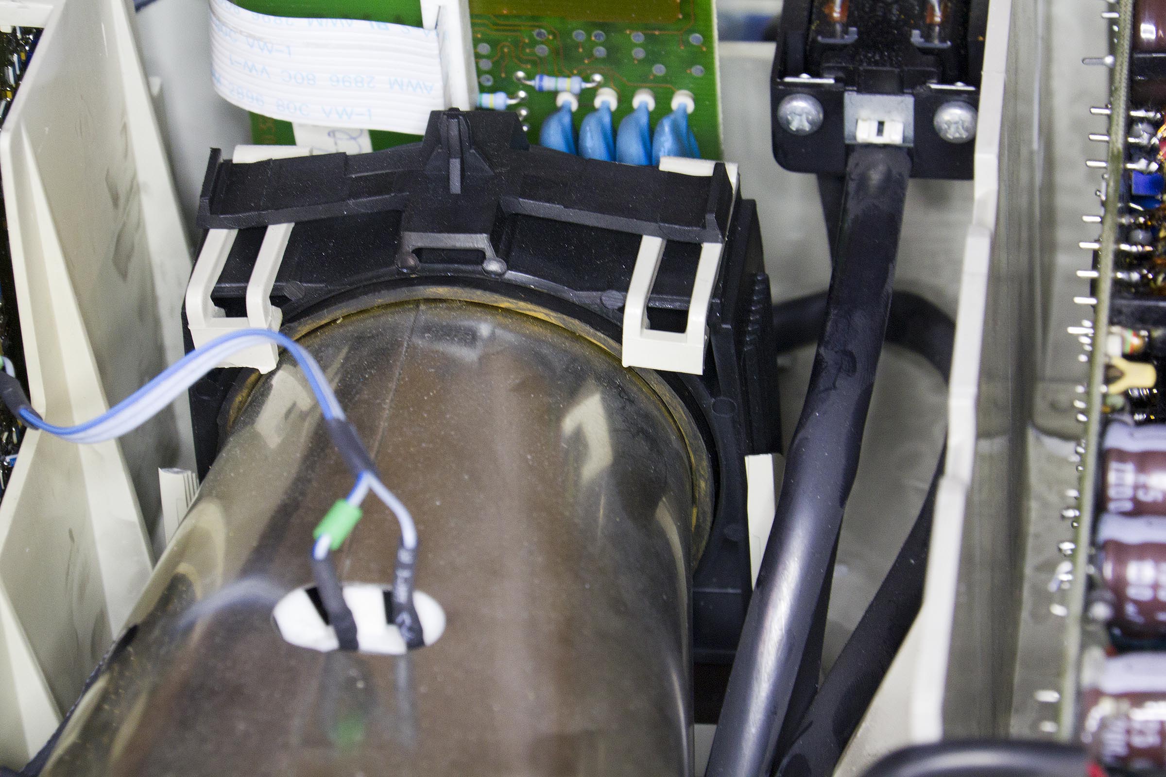
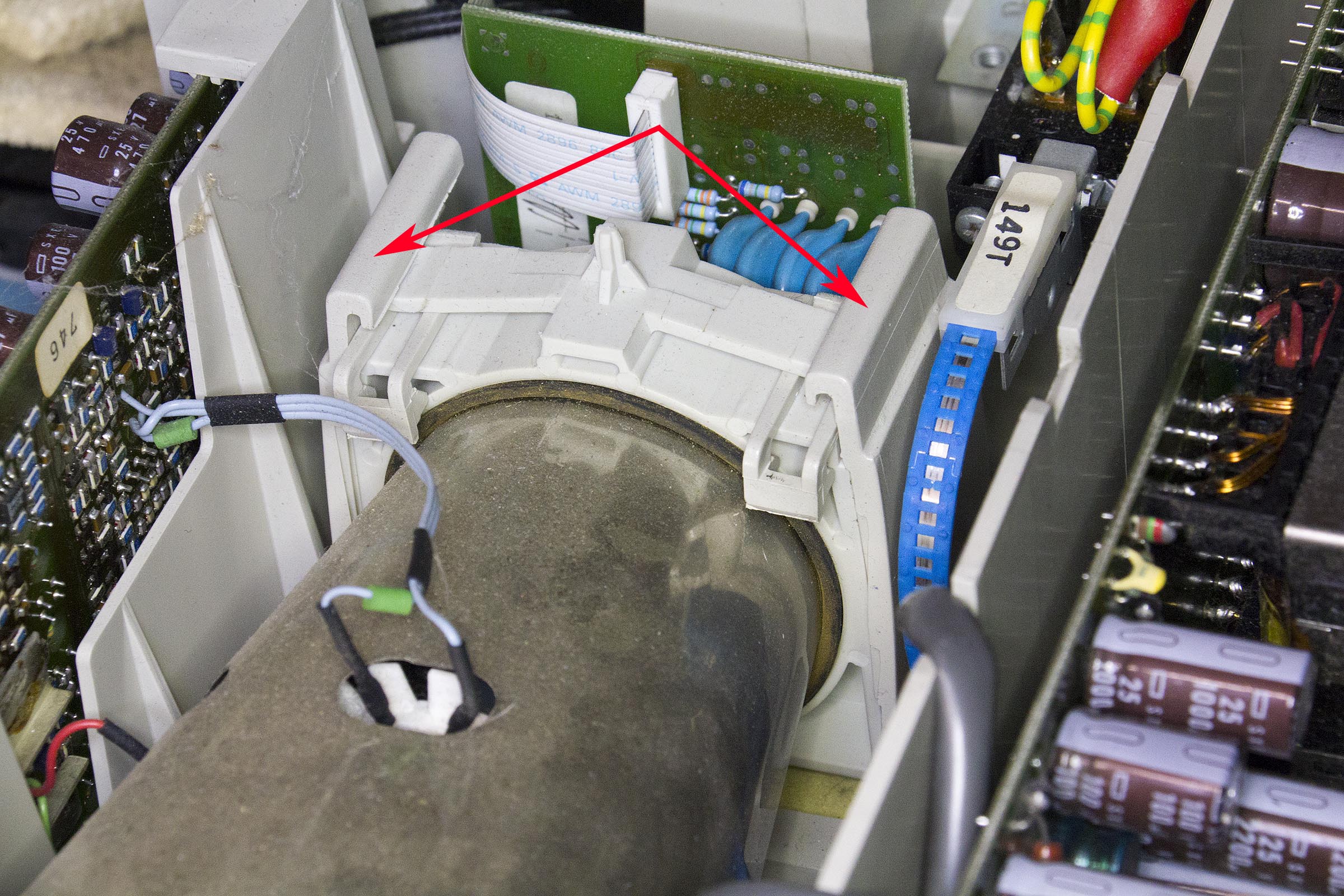
There is supposed to be a clip each side like this
Thankfully in this case the ebay seller was very apologetic and we quickly came to an agreement on a partial refund.
In fact the "A" seems to work OK, the only noise I can hear adjusting the trigger level is the normal audible click that these 'scopes make adjusting any of the rotary controls and it seems to pass a basic check of displaying a simple trace. It needs a bit of a tidy/clean-up and the inevitable battery leakage clearing out of the battery compartment but, barring surprises, looks fine.
Anyway to get back to the repair - if you recall I was stuck on the issue of riser cards. Digging through my collection of "useful things" I found a Pickering RF switch system I acquired at a Radio Rally a few years back - I liked the card case it was in and there were
lots of nice RF relays left (though the really juicy ones had already been stripped).
It had a DIN 41612 backplane, but the really interesting thing was that the sockets were actually not soldered but more cold-welded into place by the through hole plating. It was possible to lever off the socket to leave the pins sticking up out of the board, then push through each pin from the back before finally putting them back in the housing.
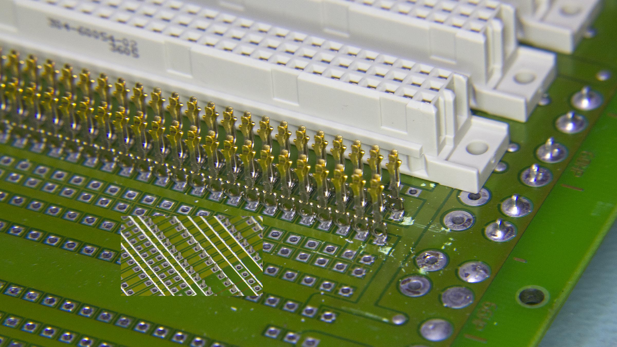
I could then stack these to form an extended connector which would allow the board to be accessed, here are the connectors on the board
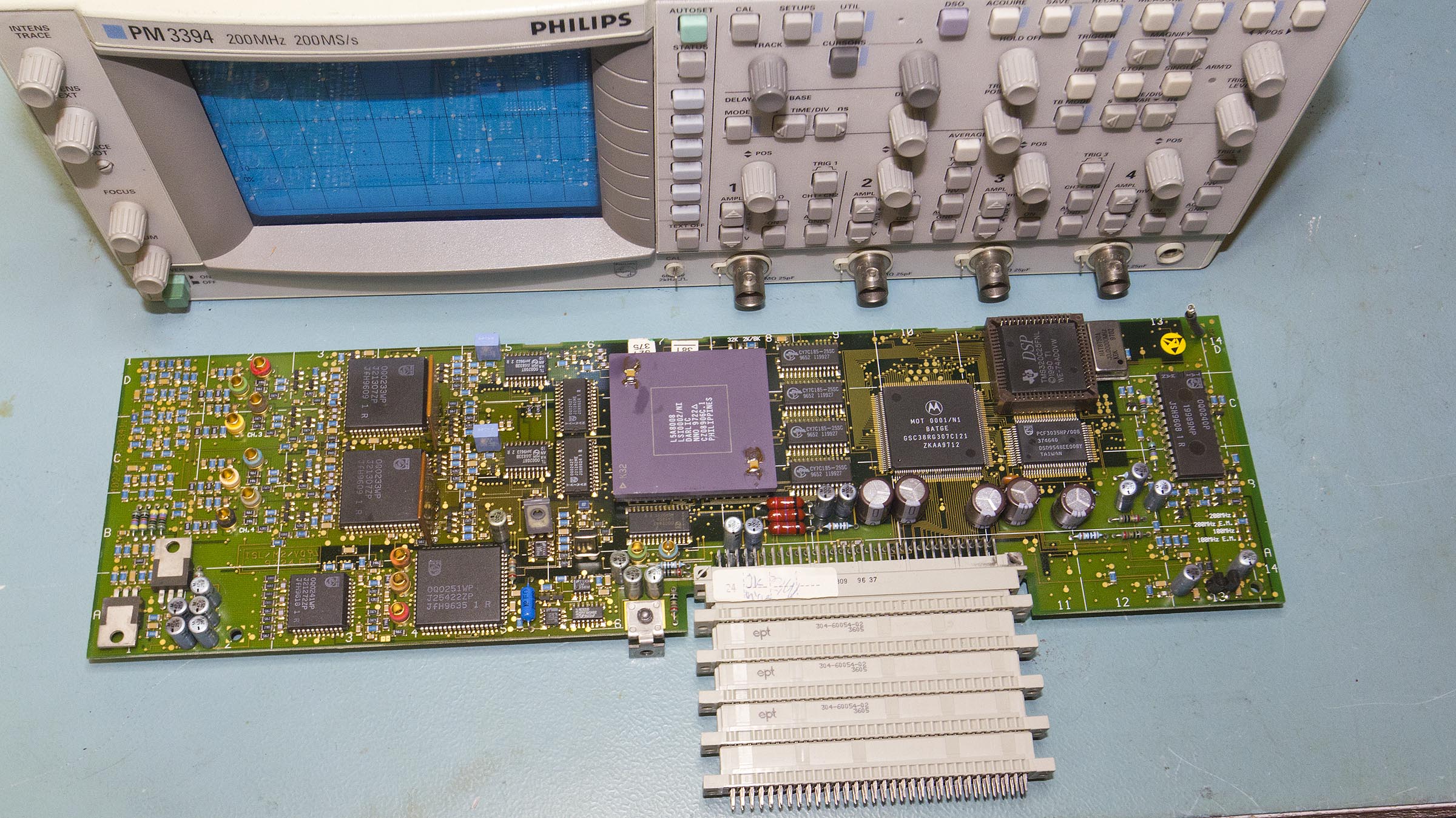
and here is the board in the 'scope
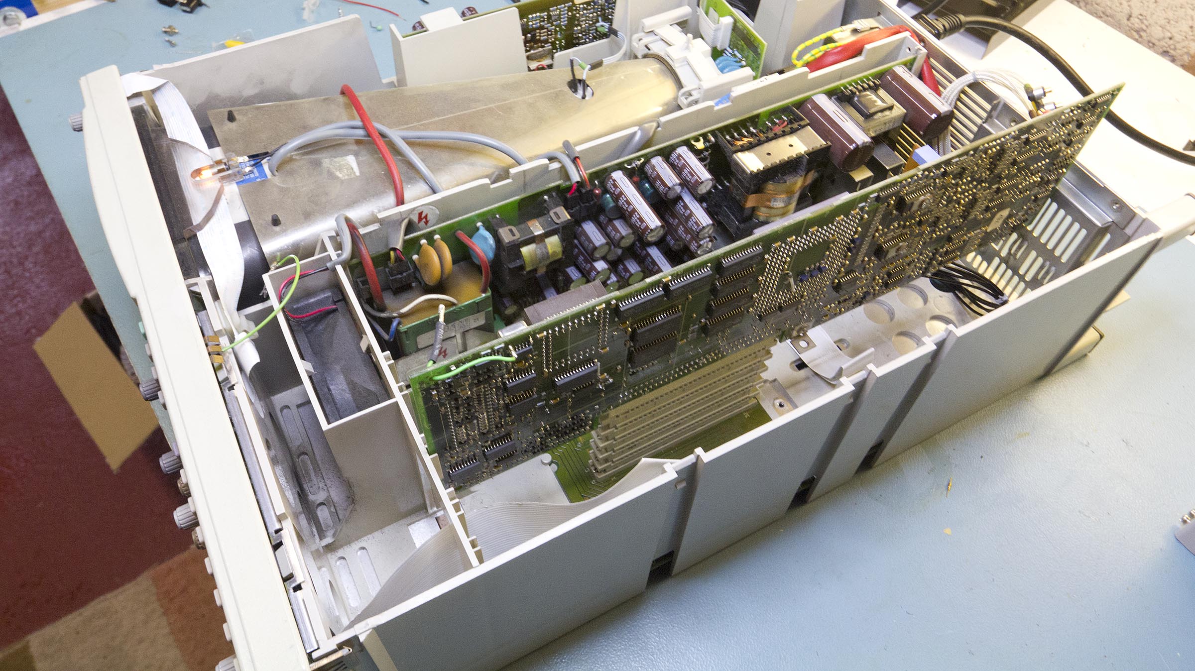
It's a bit delicate but you can see that the 'scope quite happily runs like this
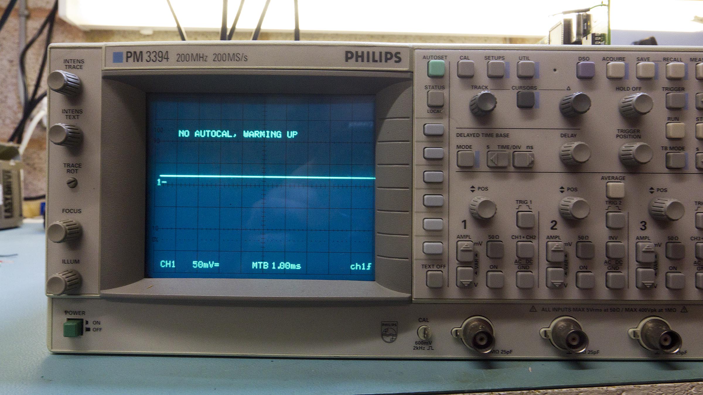
So, that was the riser card (or extend-a-nector) sorted so now I could try to probe some signals.
To recap, having fixed the CPU<->Front panel fault the remaining problems were very dim text which could not be adjusted by the text intensity control and an "DSP communications error" message on the screen at boot.
The first check was to plug in the digitiser from the 3380B - apart from the fact that I got an "A8 board wrong hardware ID", this appeared to work - in that it allowed the text intensity to be varied and would happily display four traces in both digital and analogue mode.
That confirmed a fault in the original digitiser board. At this point I considered just using the board from the 3380B as it works. That might sound a bit odd as the 3380B is a two channel 100MHz 'scope but in fact there are only a few real differences between the cards. For a start it might be that there is no 2-channel version of the DSO board - certainly the board High Voltage sent has components mounted for all 4 input channels so that just leaves the bandwidth difference.
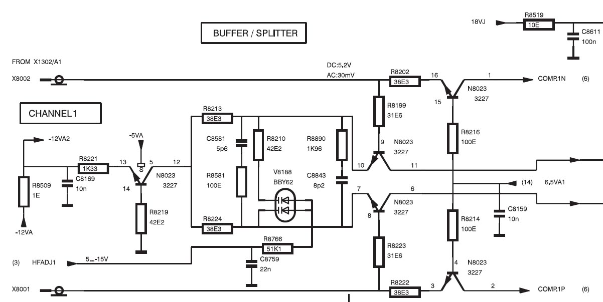
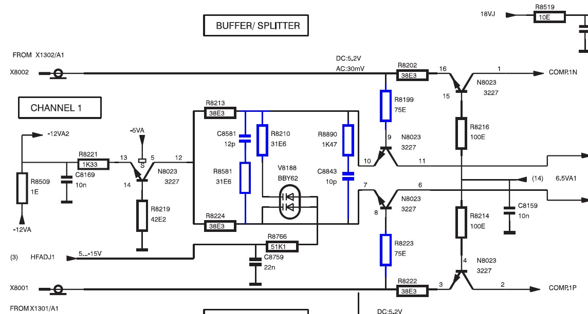
Looking over the schematics only the front end has a 100MHz and a 200Mhz version and looking in more detail at those it appears that just 7 components per channel differ - shown in blue on the 2nd (100MHz version) diagram below.
200MHz DSO front end:
100MHz DSO front end:
So, it would not be impossible to upgrade the board to 200MHz, especially as I had a donor with just the right components in situ. However I thought it would be worth persevering with the fault finding.
I was originally suspicious about the intensity control DAC and multiplexor shown below
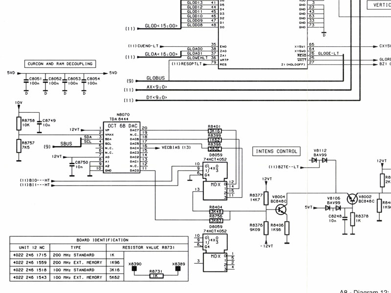
Now that I was able to probe some signals I found that the two select lines BI0 and BI1 were always low - this puzzled me quite a bit until I realised that in analogue mode the trace is switched between text and signal by a different signal and only the normal text intensity is used - the other intensities here are for DSO mode.
That exonerated the two control lines and probably the 74HCT4052 so I checked the DAC output to find that it did not vary with the text intensity control on the faulty card but did on the 3380B card. Swapping the DACs between the two boards did not fix the problem so it was not the TDA8444's.
However, if it's not the DAC then the I
2C bus falls under suspicion - but if that was hosed I couldn't understand why anything worked because all sorts of control and select signals hang from it.
Looking at the schematics afresh, the DSO board has its own I
2C bus so, along with the error message about the main CPU not being able to talk to it properly the finger of doubt pointed very clearly at the DSP.
Sure enough moving the DSP from the faulty 3394 card to the 3380B card brings the fault with it so it looks very much as the DSP is hosed. The DSP itself is a mask programmed version so the only way to obtain a replacement will be from another one of these 'scopes. Before I put the good DSP into the faulty board I want to make sure that all the voltages on the socket are OK and there isn't another fault on the board which "killed" the DSP but it looks as though the faults have now been traced to their source.
In some ways it ties in with the broken chassis. I have four of this series of 'scope - the 3382 that I regularly use, a 3394, 3394A and 3394B so I have enough to get three of the four working. I still need to see whether there is an issue with the 3394B CPU card but could always move its flash ROMs to one of the 338x boards (the 3394B CPU board would be preferable, though, as it has the GPIB hardware fitted). The 3394B DSO card has the extended maths** and extended RAM options.
The other decision I have to make (assuming nothing else is faulty) is how I want to transplant bits. I can either leave the 3382 and 3394A as is and transplant the 3394B cards to the 3394 chassis (at least the DSO board, CPU board, external trigger and Y out options as well as the front panel to get the "Vert Menu" button) which will leave me a slightly chimeric "B" for the bench and a 3394A and 3382 to sell.
Or, alternatively I can do the above and then transplant the 3394 boards into the 3382 chassis to leave me a 3394A and a plain 3394 to sell - which will be worth more than the 3382.
Finally there is also the option of copying the firmware from the "B" to the "A" CPU board. I don't think it will go on the plain 3394 as the front panel is different. I need to have a good look at the service manuals to see what hardware changes were actually made from revision to revision.
** Looking over the schematics I spot a resistor from 5V/ground feeding a pin on the DSP and labelled "option" - I wonder if all the DSPs have the maths option and it just needs to be enabled.


