Author Topic: Repair of Seat Occupancy Sensor  (Read 21571 times)

0 Members and 2 Guests are viewing this topic.

Offline ValdenTopic starter

  • Contributor
  • Posts: 47
  • Country: au
Repair of Seat Occupancy Sensor
« on: April 09, 2018, 04:47:02 am »
Hello all.

Could I ask for your help please with identifying a few components on the circuit board for the pictured seat occupancy sensor mat, from my BMW 120i. The vehicle's On Board Diagnostics are clearly pointing to it being faulty.


Before removing it from the seat (big job) and stripping away the silicon(?) that the board was encased within (bigger job) I observed open circuits between the brown (ground), red and white wires.

With the sensor out of the car and cleaned for inspection I observed that the black and white traces forming the pressure(?) sensing mat were working. The four black traces form two loops. The outer loop was reactive to having pressure applied from my daughter's hands. It would increase from around 200 ohm up to around 1400 ohm. The inner loop would remain stable at around 600 ohm.

Here is a closer pic of the board, made by Helbako in Romania. One transistor (near the top edge of the board as pictured) came apart while peeling the silicon away, after much digging with various picking tools. I need to figure out what to replace it with, having assumed it won't work. I've kept the top part, but it has no markings that I can see. The one next to it is A7s 47, with the s underlined.

But the real question is - can you help identify the 8 pin IC in the middle of the board? It's marked with embossed characters A916 and printed characters (hard to read) which I think are SCO4C in one line and RNAA0513 in a second row. Or this printing could be SCQ4C or less likely SC04C, and perhaps RMAA0513. My searches on Mouser and RS-Online have been fruitless. I've just probed this IC again with my meter set on the 2000K range, between pin 1 and the others - there is continuity between all. Doesn't mean it's good, but better than no reaction.


The resistors are all good. The larger capacitors seem OK, though not tested off-board yet. I believe the brown components are capacitors - some behave that way. Are the grey coloured components also capacitors? I'm getting no information from them.

So, do you have suggestions on how to proceed? My inclination is to focus on the 8 pin IC, but I need to identify it. And the larger caps. If it would help I could get my proper camera and tripod out and take some superb macro photos. However, I'm pretty sure I've already offered what is printed on the main IC. I might draw up a circuit diagram if the fault doesn't become obvious - should help figure out what's going on. And I'll soon start testing components with one end lifted.

I'm curious about the lack of continuity between the brown, red and white wires connecting the board to the vehicle, in light of there being what appears to be a functioning sensor mat circuit. Hmmm.

Your thoughts are welcomed. :)

Regards, Rick.
 

Offline capt bullshot

  • Super Contributor
  • ***
  • Posts: 3033
  • Country: de
    • Mostly useless stuff, but nice to have: wunderkis.de
Re: Repair of Seat Occupancy Sensor
« Reply #1 on: April 09, 2018, 07:32:06 am »
The three pin device (SOT23 or alike) at the top edge / near middle looks broken.

For the IC - I've got two guesses:
either it's a simple analog function like an amp or comparator, and the boards output is a simple on/off signal (one wire is GND, one is +12V, one output),
or it's a small application specific microcontroller interfacing to a vehicle LIN bus - in this case it's most probably unobtanium

From the vehicles ability to diagnose the sensor and tell you it's defective, the latter (micrcontroller) is more probable IMO.
Safety devices hinder evolution
 
The following users thanked this post: Valden

Offline SMdude

  • Frequent Contributor
  • **
  • Posts: 258
  • Country: au
Re: Repair of Seat Occupancy Sensor
« Reply #2 on: April 09, 2018, 07:56:08 am »
The A7 device should be a bav99 dual diode.

I'm not sure the so8 is a microcontroller. There are no programming testpoints exposed.

It's a relatively simple circuit,  it shouldn't take much to turn it into a schematic.

What pins on the so8 are power and gnd?
 

Offline nali

  • Frequent Contributor
  • **
  • Posts: 657
  • Country: gb
Re: Repair of Seat Occupancy Sensor
« Reply #3 on: April 09, 2018, 08:05:11 am »
Looks like the board has suffered some screwdriver damage there. The top of the 47u cap is stoved in, the SOT23 device as Capt B mentioned has either been broken off or exploded.

Is that brown wire actually soldered in?

If the 8-pin part was a MCU it'd probably be a mask programmed device so I wouldn't really expect to see any programming points.
 

Offline Zucca

  • Supporter
  • ****
  • Posts: 4308
  • Country: it
  • EE meid in Itali
Re: Repair of Seat Occupancy Sensor
« Reply #4 on: April 09, 2018, 11:55:06 am »
I would not invest more than 30 min in repairing that tortured boad:

eBay auction: #272029373391
Can't know what you don't love. St. Augustine
Can't love what you don't know. Zucca
 

Offline ValdenTopic starter

  • Contributor
  • Posts: 47
  • Country: au
Re: Repair of Seat Occupancy Sensor
« Reply #5 on: April 10, 2018, 01:59:35 am »
I would not invest more than 30 min in repairing that tortured boad:

I'm in much deeper than 30 minutes so far, so there's no pulling out now! One of the benefits of being recently retired ... :-)
 

Offline ValdenTopic starter

  • Contributor
  • Posts: 47
  • Country: au
Re: Repair of Seat Occupancy Sensor
« Reply #6 on: April 10, 2018, 02:36:00 am »
The three pin device (SOT23 or alike) at the top edge / near middle looks broken.

Hello and thank you Capt, SMdude, nali and zucca.

I dragged my old SLR out of its dungeon and took some proper macro photos. High magnification allowed me to read the engraving on the top half of the broken/blown three pin device, which says 'Z3' and 'S5'. It's there, resting on the 8 pin IC in the second and third photos.

Now I'm not the expert but it looks to me like this component had blown before its top came off as I peeled the silicon encasing back. I'm fairly sure I didn't break it with my pick tools during the surgery.


I think I'll be focussing on replacing this broken 3 pin component first. Do those numbers help identify it? Extra points awarded for naming a source. Top marks and kudos for a part number! :D ;)

Thanks for any help you can provide. Regards, Rick.
« Last Edit: April 10, 2018, 02:37:55 am by Valden »
 

Offline Niklas

  • Frequent Contributor
  • **
  • Posts: 395
  • Country: se
Re: Repair of Seat Occupancy Sensor
« Reply #7 on: April 10, 2018, 07:27:15 am »
SOT23 marked Z3 seems to be a 5.6V Zener.
http://www.s-manuals.com/smd/z3
 
The following users thanked this post: Valden

Offline ValdenTopic starter

  • Contributor
  • Posts: 47
  • Country: au
Re: Repair of Seat Occupancy Sensor
« Reply #8 on: August 03, 2018, 01:20:33 am »
Hello all. Good news!

It's been a few months since the last post on this passenger seat occupancy sensor. There's been times I've thought the 'Last Post' would be quite appropriate. :horse:  However, once back from a trip (go on, ask where  8) 
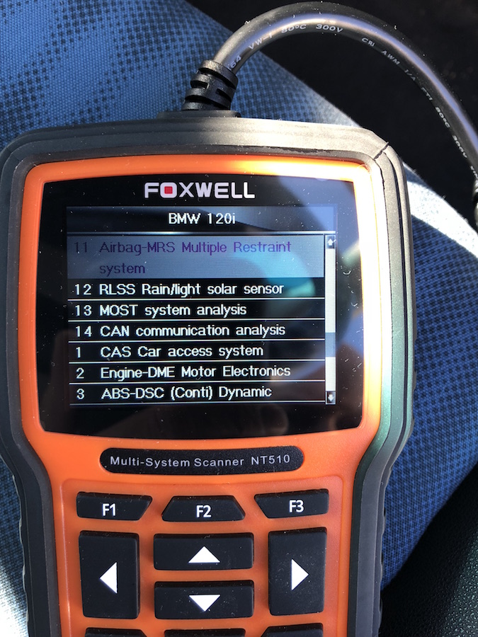
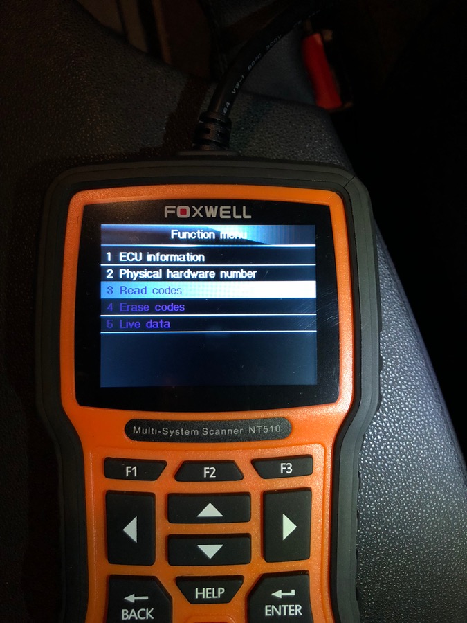
) I turned my attention to it again. The first thing I did was order a Foxwell NT510 OBD-II code scanner, so I could interrogate the car's computer and clear fault codes to see if problems were resolved.


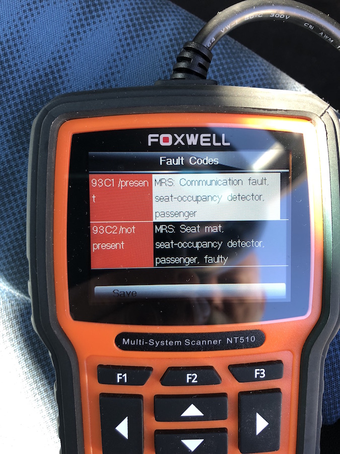
The going wasn't easy with my very basic POC 'Dick Smith' multimeter; not sensitive enough to test a few suspect SMDs I lifted from the board. I soldered them back in place, effectively but untidily, though with no improvement. Each time I plugged the sensor in under the passenger seat and then pushed the key in my BMW would go 'Bing!' and display the now familiar Malfunction Indicator Lights. The code scanner advised of two problems; a communication fault and a faulty passenger seat occupancy sensor mat. Hmmm.


I decided a reflow might help so removed the connected wires and the Force Sensing Resistor mat and warmed the board on our clothes iron, balanced upside-down. It didn't take long before the three wonky components I'd worked on settled into place. One was the smaller of the three canister capacitors, 47jFC, which sustained a broken leg during the initial stripping of the board's silicon gel encasing. Next time I'll start with the iron on a lower setting. The board looked somewhat cooked after this treatment. :( 
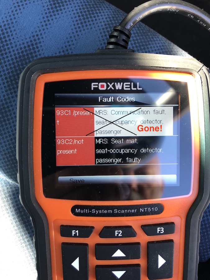
With the wires and pressure mat back in place and a stand-in 5.6V Zener diode soldered on (thank you Niklas) I ran another test in the car and was encouraged when the computer decided it could now talk properly with the sensor. I was down to only one fault code - a small success. :)


At about this point wifey kindly proposed that my determination warranted reward with a Fluke 289. :-DMM Boy oh boy has that been handy. If I did at some stage mention that it was probably repeat application of pressure from her petite posterior that broke the sensor in the first place ... well, that might have cost me an upgrade.  :-BROKE 

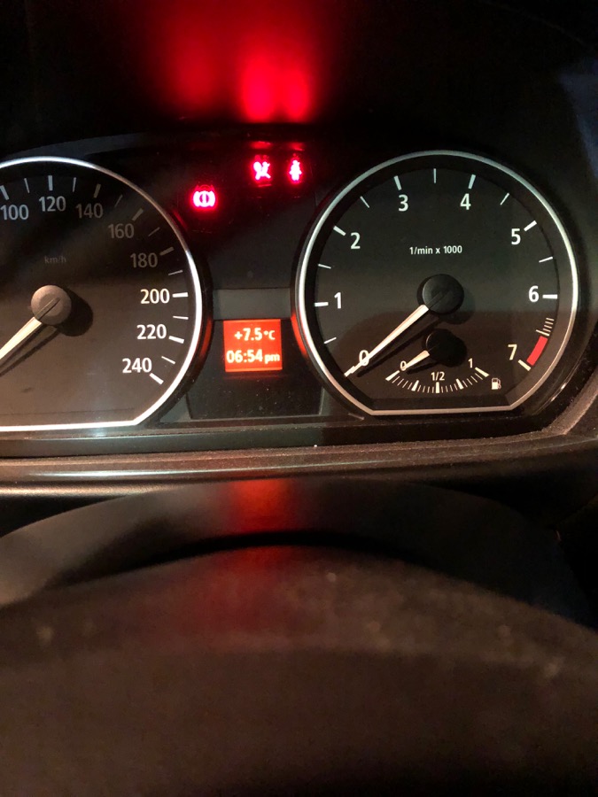
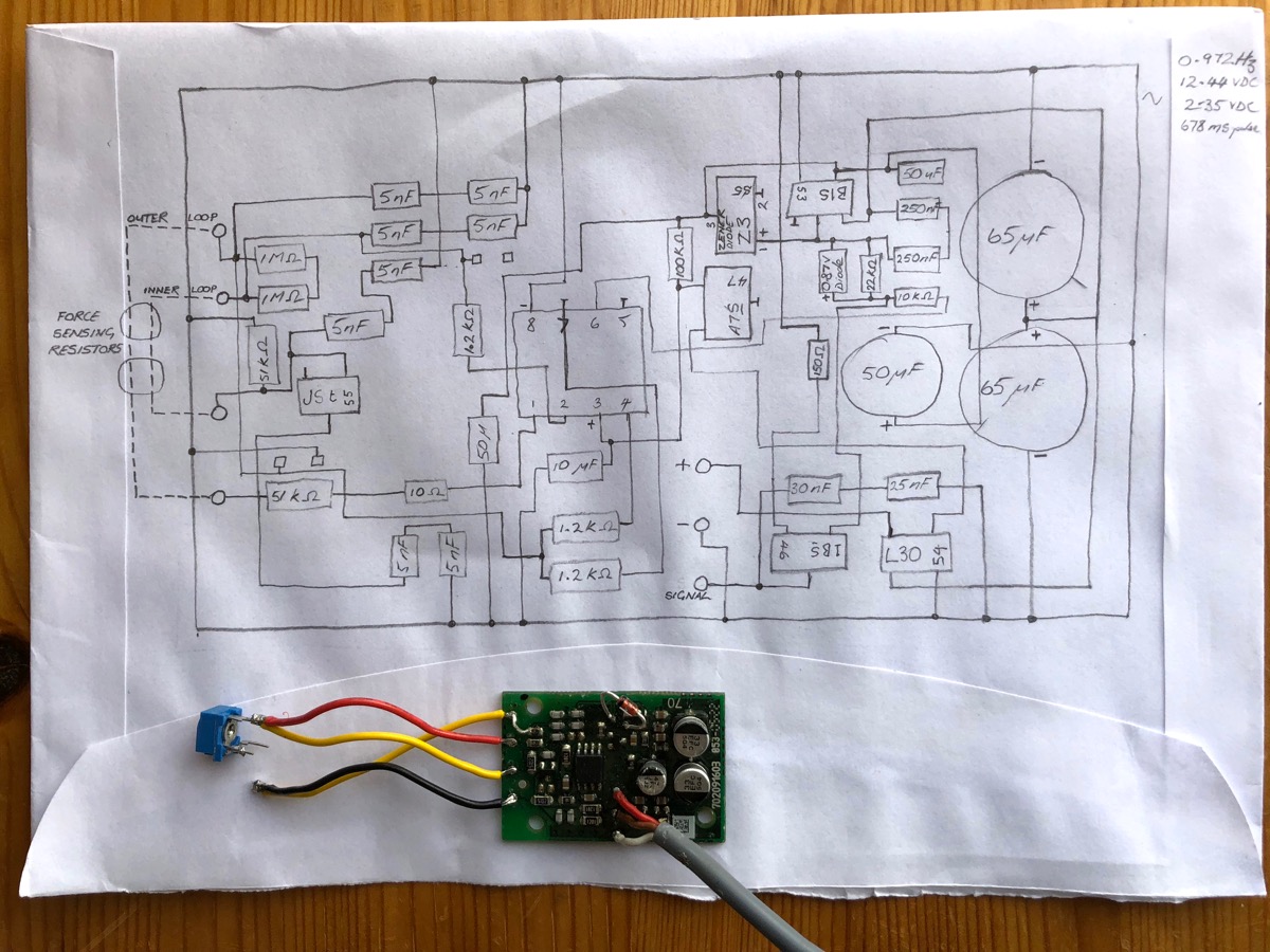
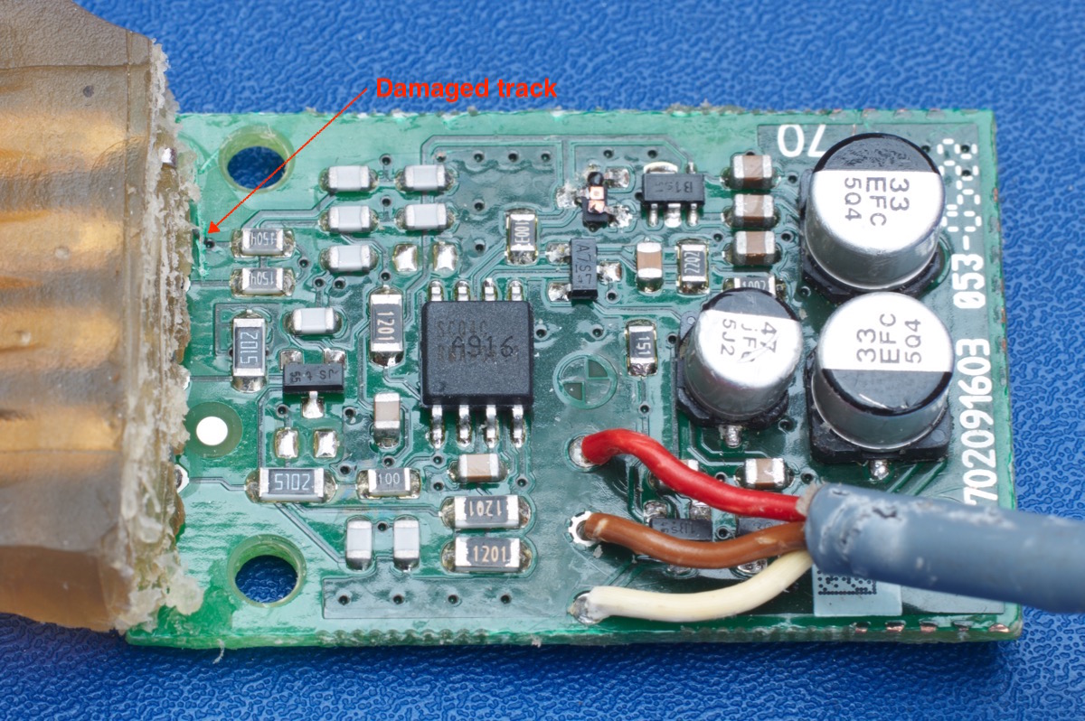
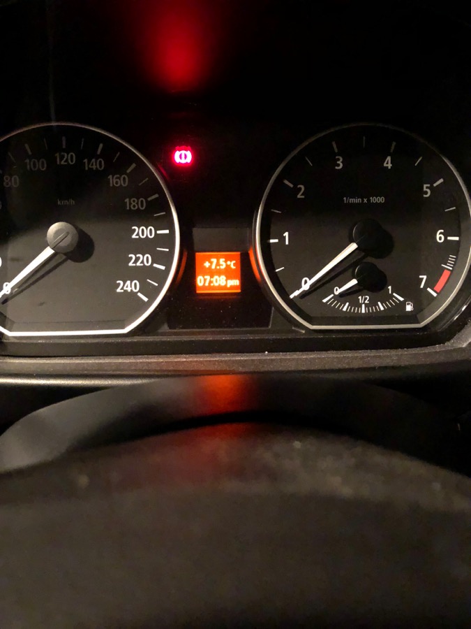
I followed SMdude's advice and drew up a schematic, on the back of an envelope. The 289's multi-range continuity function was particularly helpful with this. The Fluke's sensitivity also allowed me to assess that all of the components were working, seemingly. When I was cross-checking my schematic against the board yesterday morning I found that a scratched track which had tested OK before (with my old, cheapo meter) was in fact open. The screwdriver damage that nali noticed, at top left in the picture below the schematic, might have been hanging on by a thread at first or might have been broken all along. I soldered a temporary bridge in place and looked forward to running another test in the car, upon its return with wifey in the evening. That test was done in the cold, dark driveway last night and with the old fault codes cleared, the car did not go 'Bing!'. :D


Now that I know the board has life in it and that the extent of the Safety Restraint System fault is limited to it alone, I'll continue with making a tidy and complete repair and assess its suitability for installation back into the seat. A problem with these sensors is that there isn't an easy way, if at all, to determine what a working sensor is telling the ECU with respect to seat occupancy status. If the sensor serves up a 'no passenger' signal, the passenger airbag might not go off when it ought to. Crash dynamics and vehicle programming are variables. This problem would not be completely eliminated by installing a new replacement sensor/seat mat. False negatives would still go undetected. The point of these passenger seat occupancy sensors is two-fold: to reduce repair costs after lower level accidents by not firing the passenger seat airbag if it's not needed; and, in the situation where mum or dad is driving around the parking lot with junior standing in the footwell and leaning on the dash, to avoid blowing the child out the back window. It's happened.

I'm rather pleased that I've avoided the expense of a maintenance action that might not have worked, by spending about twice as much as the replacement part alone on a quite wonderful multimeter and a really handy code scanner. :D I might still buy a new sensor mat, but at least I'll know it's the correct repair.

In case anyone finds this thread by searching, some details about this passenger seat occupancy sensor mat from my 2005 BMW 120i E87 are:

- the 8 pin IC in the middle of the board generates an oscillating wave of 0.972Hz and approximately 12V amplitude. I've concluded that the car's ECU looks for this signal to determine that the sensor is present. It also checks for the integrity of the sensor's Force Sensing Resistor mat itself.
- the sensor mat comprises inner and outer loops of traces interconnected by Force Sensing Resistors. My wife's bottom causes the resistance between the inner and outer loops to change from infinite with no force applied to approximately 200kOhm with her 47kg of weight sat on it. During my testing I used a 216kOhm trim pot to simulate my wife's bum.
- my BMW dealer charges AUD$498 for a new mat and probably twice that for installation.
- the Zener diode I needed to get my passenger seat occupancy sensor working cost 65 cents. A proper SMD one might cost a bit less though. ;)

Regards, Rick.
« Last Edit: August 03, 2018, 01:22:28 am by Valden »
 
The following users thanked this post: amyk

Offline james_s

  • Super Contributor
  • ***
  • Posts: 21611
  • Country: us
Re: Repair of Seat Occupancy Sensor
« Reply #9 on: August 03, 2018, 03:54:18 am »
Is it possible to just bypass the thing?

Whenever I work on a car this era I find myself wishing I could just rip out about half the electronic gadgets and just have a car without all the distractions. I like the computerized engine management, ABS, stuff like that but that had all matured by the early to mid 90s and then they started just adding fluff. Technology for the sake of technology.
 

Offline ValdenTopic starter

  • Contributor
  • Posts: 47
  • Country: au
Re: Repair of Seat Occupancy Sensor
« Reply #10 on: August 03, 2018, 04:22:48 am »
I guess if I was to leave the sensor with a resistor that approximates the weight of my wife's bum-on-seat wired in between the inner and outer Force Sensing Resistor loops, well, that would have the effect of letting the car know there was always someone sitting in the passenger seat. And that would be fine if I never allowed a child to sit there. They certainly won't be standing there. But what about the next owners?
 

Offline james_s

  • Super Contributor
  • ***
  • Posts: 21611
  • Country: us
Re: Repair of Seat Occupancy Sensor
« Reply #11 on: August 03, 2018, 05:18:25 am »
I guess it depends. I didn't hesitate to remove the airbag from my '90 so I could install the nicer steering wheel from the '87 that got rear ended. There won't be a next owner, I'll drive the car until the next time someone hits me hard enough to make it unrepairable as happened to my last car.

When it comes to old cars I don't think I've come across one that didn't have a few surprises hiding, and one can always inform the next owner of any modifications that were done. I keep a spreadsheet tracking all of the maintenance and repairs.
 

Offline ValdenTopic starter

  • Contributor
  • Posts: 47
  • Country: au
Re: Repair of Seat Occupancy Sensor
« Reply #12 on: August 03, 2018, 05:23:13 am »
I like your approach. Reminds me of when I bought a fleet of Land Rovers for our Defence force, at the start of my career. Thousands of them. They were sold off at the end of my career, still working, though many had been subject to a 'grandma's axe' experience. :)
 

Offline Zucca

  • Supporter
  • ****
  • Posts: 4308
  • Country: it
  • EE meid in Itali
Re: Repair of Seat Occupancy Sensor
« Reply #13 on: August 03, 2018, 07:18:48 am »
Is it possible to just bypass the thing?

In modern cars, bypassing is a mess just FAI.

I guess if I was to leave the sensor with a resistor that approximates the weight of my wife's bum-on-seat

and keep the passenger seatbelt fastened all the time, otherwise bing bing bing bing...  :horse:

Congratulations for the repair. Let me ask something, would it not be better to buy a replacement unit in the first place?
I am like you, I want to fix everything. My problem at the end I look back and ask myself if it was worth or not. Then 99% I tap on my shoulder saying:"You learned something, well done dude" and move on.  ::)


Can't know what you don't love. St. Augustine
Can't love what you don't know. Zucca
 

Offline ValdenTopic starter

  • Contributor
  • Posts: 47
  • Country: au
Re: Repair of Seat Occupancy Sensor
« Reply #14 on: August 03, 2018, 07:31:32 am »
Hi Zucca.

Yeah, we're the same. We like to get things working again. Who really wants to pay $500 for a spare part when it's only a 65 cent, replaceable component that's blown? However, if I can't get the sensor board and the pressure mat properly and safely integrated back into the seat, I'll happily buy a new one, knowing that it was beyond repair and not simply in need of a little TLC. Feels better that way. 
 

Offline james_s

  • Super Contributor
  • ***
  • Posts: 21611
  • Country: us
Re: Repair of Seat Occupancy Sensor
« Reply #15 on: August 03, 2018, 03:59:40 pm »
I completely agree there, I would much rather fix something than buy a new one. I just get annoyed at so much of this designed to fail stuff that adds no value. I always put my seatbelt on, I feel naked without it. I don't need a gadget to nag me into doing so, it's just one more thing to break.
 

Offline amyk

  • Super Contributor
  • ***
  • Posts: 8270
Re: Repair of Seat Occupancy Sensor
« Reply #16 on: August 04, 2018, 12:21:37 am »
Great write-up! Your manual schematic skills are nice too. It looks like a relatively simple analog circuit, the IC doesn't look like it's a microcontroller. I'd guess it is a Motorola SCQ4C, although that doesn't help because you can barely find information on that either... but it's likely to be something simple and analog. If you can figure out what the output is supposed to be and how it changes in proportion to weight, then making a compatible board with jellybean parts might not be that hard.

In case anyone is curious, the SMDs on there are (most of them are diodes, and made by Philips/NXP/Nexperia):

JS: BAS21 diode
A7s: BAV99 dual diode
Z3: BZX84C5V6 zener diode (as noted above)
1Bs: BC846B NPN transistor
B1s: TLE4285G 5V regulator
L30: BAV23 dual diodes
 
The following users thanked this post: Valden

Offline ValdenTopic starter

  • Contributor
  • Posts: 47
  • Country: au
Re: Repair of Seat Occupancy Sensor
« Reply #17 on: August 04, 2018, 02:24:20 am »
Thanks Amyk. Great info on the IC and the SMDs. I'll be ordering a replacement for the Z3 Zener diode.

FYI - the three codes I found printed on the IC are:

- SCQ4C - printed
- RNAA0513 (or RMAA0513 - hard to read) - printed
- A916 - stamped

Does this help nail it down? It'd be good if it wasn't proprietary.

Here's a close up of the labelling.  Rick.


Offline ValdenTopic starter

  • Contributor
  • Posts: 47
  • Country: au
Re: Repair of Seat Occupancy Sensor
« Reply #18 on: August 15, 2018, 02:40:36 am »
Hello gentlefolk. Could I please have your thoughts on some test results I’m seeing? Thanks.

As discussed, I've repaired the circuit board of the passenger seat occupancy sensor from my BMW 120i, a 2005 model with an E87 chassis. I've been studying it with my multimeter to identify how it informs the car's ECU that there's a passenger on the seat.

For the moment I’m using two wire loops interconnected by a switch and a trim pot to emulate the resistance normally provided by the Force Sensing Resistors in the seat mat. Switch open = no continuity between the loops = no passenger. Switch closed and trim pot at 100kOhm = my wife’s weight on the Force Sensing Resistor mat.

With 12V DC hooked up to the circuit board on the bench and then testing between the positive and signal wires with my DMM, the only interesting readings I’m getting are in the mV AC mode, and then measuring frequency, which changes with ‘weight’.

- when there is an open circuit between the inner and outer loops of the seat mat (i.e. no passenger) the frequency is 1.000Hz, exactly.

- when there is 100kOhm resistance between the loops of the seat mat (i.e. a small adult is sitting on the mat) the frequency is 3.000Hz

- when the trim pot is dialled down to a lower resistance setting, to simulate a heavy adult passenger, the frequency changes to 2.000Hz. The change from small to big adult occurs at around 80kOhm.

These results don’t look random to me.

I’m curious about how low the millivolt readings I’m seeing are. There is a steady pulse of around 1Hz from approximately 10mV to 25mV with each of these readings, though, the bar graph on my Fluke 289 does reveal changes in the beat of the pulse. It’s a smooth oscillation when the frequency is measured at 3.000Hz or 2.000Hz (small adult and big adult passengers) but changes to a double beat when the frequency is 1.000Hz (no passenger = open circuit between the inner and outer loops of the mat). With this double beat, the first rise is about half the scale of the full rise to ~ 25mV.

Thoughts?

Is this what the Motorola SCQ4C IC does?

Do I need an oscilloscope? :) Your replies will be read out aloud in our kitchen.

Thanks. Rick.
 

Offline Rasz

  • Super Contributor
  • ***
  • Posts: 2616
  • Country: 00
    • My random blog.
Re: Repair of Seat Occupancy Sensor
« Reply #19 on: August 15, 2018, 03:29:10 am »
by spending about twice as much as the replacement part alone on a quite wonderful multimeter and a really handy code scanner.

according to my calculations it was $50 replacement(used) sensor vs $850 in tools, but whatever :)

I’m curious about how low the millivolt readings I’m seeing are. There is a steady pulse of around 1Hz from approximately 10mV to 25mV with each of these readings, though, the bar graph on my Fluke 289 does reveal changes in the beat of the pulse. It’s a smooth oscillation when the frequency is measured at 3.000Hz or 2.000Hz (small adult and big adult passengers) but changes to a double beat when the frequency is 1.000Hz (no passenger = open circuit between the inner and outer loops of the mat). With this double beat, the first rise is about half the scale of the full rise to ~ 25mV.

Do I need an oscilloscope? :) Your replies will be read out aloud in our kitchen.

Yes! now you just need a $350 scope :D

Is this what the Motorola SCQ4C IC does?

wouldnt be surprised if it was a variation on 555, hardened and modified for this particular use
Who logs in to gdm? Not I, said the duck.
My fireplace is on fire, but in all the wrong places.
 

Offline ValdenTopic starter

  • Contributor
  • Posts: 47
  • Country: au
Re: Repair of Seat Occupancy Sensor
« Reply #20 on: August 15, 2018, 05:27:11 am »
I'd be glad to get a replacement for $50. The only ones in my part of the world are new, and cost $500.  :o

This sensor mat failing and my 'need' to fix it was the perfect excuse to buy a really good DMM. Thank you for your advice that I now need a top-o-the-line $3500 O-scope. There was a typo in your message. You left a 0 off.

I will investigate this 555 variant. Clues appreciated.

Regards, Rick.
 
The following users thanked this post: Zucca

Offline Rasz

  • Super Contributor
  • ***
  • Posts: 2616
  • Country: 00
    • My random blog.
Re: Repair of Seat Occupancy Sensor
« Reply #21 on: August 15, 2018, 07:35:25 am »
I'd be glad to get a replacement for $50. The only ones in my part of the world are new, and cost $500.  :o

$500 is what a perfect complete set of front 2004-2011 E87 seats cost at the wreckers
 so so seat $45 https://www.ebay.com.au/itm/BMW-1-SERIES-LH-PASSENGER-FRONT-SEAT-E87-10-04-04-05-06-07-08-09-10-11-12-13/272836377830

btw didnt bmw have a ton of recalls on those sensors ~2013?

https://www.productsafety.gov.au/recall/bmw-5-7-series-seat-occupancy-sensor
https://www.foxbusiness.com/features/bmw-recalls-over-85000-vehicles-in-u-s-over-faulty-airbag-sensor
Who logs in to gdm? Not I, said the duck.
My fireplace is on fire, but in all the wrong places.
 

Offline ValdenTopic starter

  • Contributor
  • Posts: 47
  • Country: au
Re: Repair of Seat Occupancy Sensor
« Reply #22 on: August 15, 2018, 07:41:28 am »
thanks for the eBay links.

Re the recalled sensors, I PMed with an eBay seller in the UK. He was cagey about the source. The price was well over 200x my anticipated repair cost (parts only - not including fancy new tools!), plus shipping to the other side of the world. Pass.
 

Offline geo999

  • Contributor
  • Posts: 13
  • Country: ro
Re: Repair of Seat Occupancy Sensor
« Reply #23 on: June 16, 2020, 05:45:54 pm »

Hi guys,

this post was very useful to me as I was investigating the "93c1 MRS: Communication fault seat-occupancy detector passenger" error.

the oscilloscope showed some potentially valid signals and it only took several tries to clear the fault memory in the MRS until the error disappeared (for now).

the 1Hz picture is the "idle position", seat empty, and the other one is with 80kg in the seat.
it looks like the weight encoding it's not a continuous frequency but something different.


Regards,
Geo


Offline ValdenTopic starter

  • Contributor
  • Posts: 47
  • Country: au
Re: Repair of Seat Occupancy Sensor
« Reply #24 on: June 16, 2020, 10:12:22 pm »
Hi Geo. Thanks for letting me know you found the thread useful. We always hope someone gets some value out of posts like these.

Re your thought that the sensor/board does not appear to be providing a continuous message to the car’s computer, I believe you are right. What I found was that while the output from the seat mat was continuous, this was converted by the seat mat’s circuit board into a three stage result, signalling the states to the computer: the seat is empty; the seat has a light passenger; the seat has a heavy passenger. I think this will be taken into account by the computer, along with other data about the crash that is in progress, to decide whether to discharge none, one or two propellant charges.
 

Offline aqibi2000

  • Regular Contributor
  • *
  • Posts: 211
  • Country: gb
Re: Repair of Seat Occupancy Sensor
« Reply #25 on: January 09, 2021, 04:07:42 pm »
Looks like a LIN message
Tinkerer’
 

Offline geo999

  • Contributor
  • Posts: 13
  • Country: ro
Re: Repair of Seat Occupancy Sensor
« Reply #26 on: January 13, 2021, 11:06:02 am »
it might look like it but there's no digital component on the board that is generating this signal
 

Offline Stig997tt

  • Newbie
  • Posts: 1
  • Country: gb
Re: Repair of Seat Occupancy Sensor
« Reply #27 on: February 23, 2021, 03:33:31 pm »
I stumbled upon this forum whilst looking for information about the passenger occupancy sensor that is also faulty in my 1 series. I know this thread is now nearly 3 years old but wondered if the OP ever got his sensor to work. I looked at the partly drawn schematic that the OP did and it’s fairly obvious to me that the SO8 ic is a microcontroller running off 2.1V on pin 3. The digital output is driven by the open collector transistor BC846 and most of the RHS of the schematic is just voltage regulation. The zener that the OP had blown is only acting as a crowbar for any voltage spikes that manage to get through the TLE4285G 5V regulator so assuming it was not shorted, the circuit should have continued to work albeit without surge suppression. I will be debugging my sensor output on a DSO soon as it works most of the time. I can post results here if anyone is interested.
 

Offline ValdenTopic starter

  • Contributor
  • Posts: 47
  • Country: au
Re: Repair of Seat Occupancy Sensor
« Reply #28 on: April 02, 2023, 10:50:38 pm »
Hello Stig.

Sorry for the late reply. I only just saw this. Must check my email notification settings.

Yes, I did get the board to work. I replaced two components; the blown zener, and I installed a resistor to simulate the weight of my wife’s petite bum on the seat. This resistor sits in place of a resistance from the seat pad. I had my wife sit on the pad, measured the resistance it generated, installed a resistor of that value and checked the frequency the board was sending to the car’s computer. The car is now hard wired for a light adult passenger. The airbag fault light in the dash is no more.

I’m now waiting for one of my kids, or my wife, to crash the car. I expect to see the passenger airbag, even if they’re driving alone.

Your circuit reading skills are impressive. It’s been ages but I would enjoy further thoughts you might like to share.

Regards, Rick.


Share me

Digg  Facebook  SlashDot  Delicious  Technorati  Twitter  Google  Yahoo
Smf