Author Topic: Restoration : HP 8642B SigGen  (Read 4323 times)

0 Members and 1 Guest are viewing this topic.

Offline TiNTopic starter

  • Super Contributor
  • ***
  • Posts: 4543
  • Country: ua
    • xDevs.com
Restoration : HP 8642B SigGen
« on: July 02, 2016, 06:25:42 pm »
Time for some non-typical repairs for volt-nut, meaning myself.

Some might remember my help on 1-day repair of sick 34401A for Taiwan student, Sonic.

Well, few weeks ago he contacted me again, this time with larger haul..


Overall everything is superdirty and ugly. But we saw worse, aren't we?  :-X


Loving these old HP instruments with service maps right on the cover!


Oh, my... RF magic, I have no idea what any of that does. Time to learn something new!


Thing actually does power on..


But keypad is unresponsive... I can get some keys to work once in 100 presses...

Anyone have idea how to clean keys on these generators. Any ideas and hints to avoid wrecking all that 35kg (76lbs) of 30-year old design are very appreciated!
YouTube | Metrology IRC Chat room | Let's share T&M documentation? Upload! No upload limits for firmwares, photos, files.
 

Offline ManateeMafia

  • Frequent Contributor
  • **
  • Posts: 730
  • Country: us
Re: Restoration : HP 8642B SigGen
« Reply #1 on: July 02, 2016, 07:02:25 pm »
I found a link here

http://www.rbarrios.com/projects/HPSWITCH/

Also, there was some talk on hp/agilent yahoo group here...

https://groups.yahoo.com/neo/groups/hp_agilent_equipment/conversations/topics/74231

There is a mention that there may be grease behind the keys that could have dried up, so a good cleaning is in order.
 

Offline nidlaX

  • Frequent Contributor
  • **
  • Posts: 663
  • Country: us
Re: Restoration : HP 8642B SigGen
« Reply #2 on: July 03, 2016, 01:02:32 am »
More TiN repairs! :popcorn:

I like that backlight, is it EL?

Also, it's interesting to see how HP's aesthetic design evolved over the years. First you have those old style buttons and HP logo from 70s, but then you have the segmented LCD display from the 80s.
« Last Edit: July 03, 2016, 01:06:11 am by nidlaX »
 

Offline orin

  • Frequent Contributor
  • **
  • Posts: 445
  • Country: us
Re: Restoration : HP 8642B SigGen
« Reply #3 on: July 03, 2016, 01:23:31 am »
Also, there was some talk on hp/agilent yahoo group here...

https://groups.yahoo.com/neo/groups/hp_agilent_equipment/conversations/topics/74231

There is a mention that there may be grease behind the keys that could have dried up, so a good cleaning is in order.


And here:

https://groups.yahoo.com/neo/groups/hp_agilent_equipment/conversations/topics/77068


That link might be members only, so to quote Chuck Harris:

"There is no need, nor is it desirable to disassemble the
key switches.

The sticky lubricant is easily removed. First remove the
keyboard from the front panel, so that you can see the circuit
board, and all of the switches. Do *NOT* remove the key tops.

A brush, and a cup of 91% isopropyl alcohol is all you need.
Tip the board onto its side, over a small pan, and slop lots
of alcohol all over the switch area with the brush. When it
is thoroughly wet, cycle each of the buttons repeatedly. They
should start to free up. After you are done with that, slop
lots of alcohol once again, and again cycle each of the buttons.

One final wash down with alcohol, and you can then shake, or
blow the board dry with air... be gentle, you don't want to
blow the springs loose.

Then put the board in a warm place and let it dry totally.

The buttons do not need any lubricant. They will feel great
after washing."


There was some argument after that, but the above sums up the thread.  Use 91% IPA to clean the switches.  A later comment indicated that some plastics can crack when soaked in IPA, so to quote Chuck again:

"So, don't soak for a long time. Just wash, shake off the leftover drops
(removes more of the contaminants) and dry."
 

Offline xrunner

  • Super Contributor
  • ***
  • Posts: 7511
  • Country: us
  • hp>Agilent>Keysight>???
Re: Restoration : HP 8642B SigGen
« Reply #4 on: July 03, 2016, 02:07:51 pm »
Oh boy - this will be interesting.  :popcorn:
I told my friends I could teach them to be funny, but they all just laughed at me.
 

Offline TiNTopic starter

  • Super Contributor
  • ***
  • Posts: 4543
  • Country: ua
    • xDevs.com
Re: Restoration : HP 8642B SigGen
« Reply #5 on: July 03, 2016, 04:35:43 pm »
That's tiny incandescent lamp back-light   :D

orin
Thanks for hints, I did try bit of IPA soak into keys and pressing them and wiggling for few dozen times, it definately improved a lot, now half  of keypad actually work on second or third keypress...
I'd do thorough cleaning and IPA/distilled water bathes (PCB contacts and contact brush are gold plated, so should be no much issues).

Hooked output to my scope, there is correct output and both frequency (tried from 10MHz to 2110MHz) and amplitude (my scope can't measure below -60dbm, but everything above including +20dbm works). So settings working as supposed to be, which is great news.

So yea, this will be interesting. I still think I'd peek carefully inside those plumbing house module by module....
YouTube | Metrology IRC Chat room | Let's share T&M documentation? Upload! No upload limits for firmwares, photos, files.
 

Offline TiNTopic starter

  • Super Contributor
  • ***
  • Posts: 4543
  • Country: ua
    • xDevs.com
Re: Restoration : HP 8642B SigGen
« Reply #6 on: February 18, 2019, 10:18:34 am »
Just after 3 years, I'm back on repair attempt for this box...

Disclaimer

Real RF engineers likely to get lot of facepalms out of this thread, so if I'm going to do something wrong - feel free to point out. I mostly play in DC domain with 3458A's and calibrators, so lots to learn about RF basics still. I'm no guest to high-speed digital design stuff though, so hopefully will not make too much broken hardware...

Okay, back to generator.

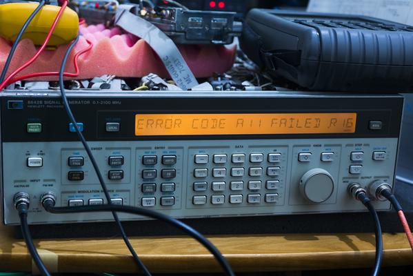
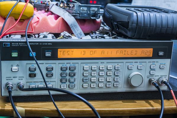
It does power on, but error out right away, saying that A11 reference loop is unlocked. Some of the frequencies seem to work fine however, and amplitude is correct at the output.


After weekend of troubleshooting, I've confirmed that SAWR A7 assembly is OK, FM loop is OK. These are the inputs of the reference loop assembly A11. Power rails +5/-5V, +15/-15V and +50VDC also confirmed all good, no easy get-away repairs on this one.

I have bought (actually twice, lol) a set of service manuals for 8642B from great and mighty ArtekManuals, highly recommend if you looking for HP and other manuals. So let's look at the A11 block diagram:


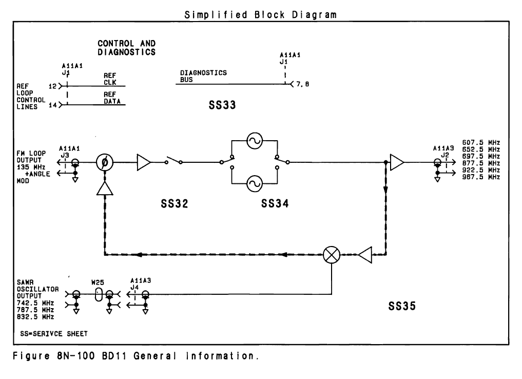
A11 takes 135MHz from FM board, one of three signals from SAWR oscillator board and generate one of the six possible frequencies at the output.

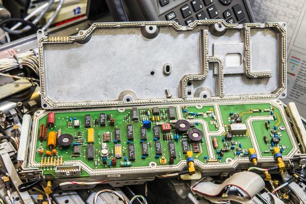
Module block SS32 is phase detector, diagnostic circuits and filters that will look at incoming signals and generate tune DC voltage to tune VCO block SS34. Here's VCO in question:


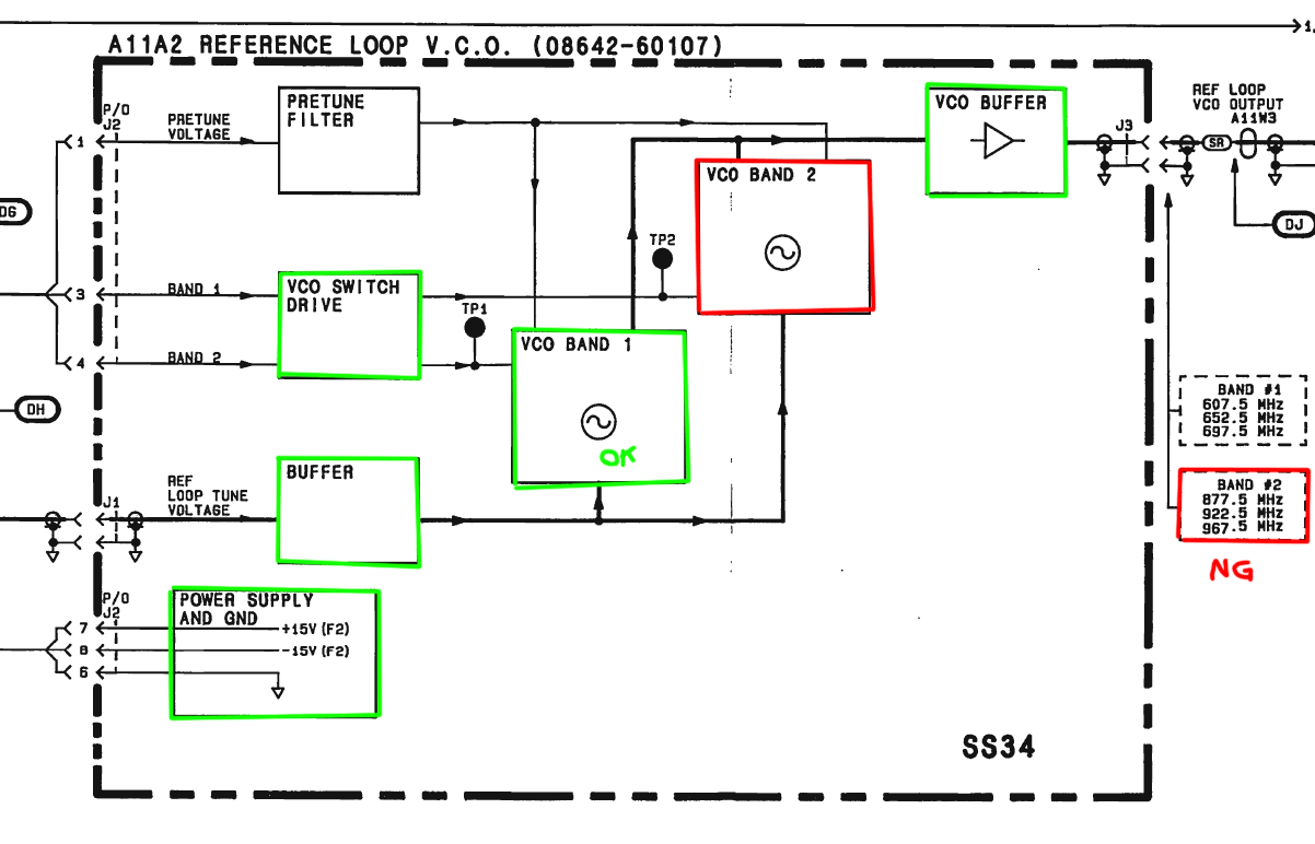
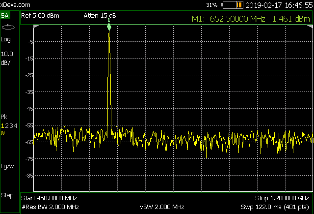
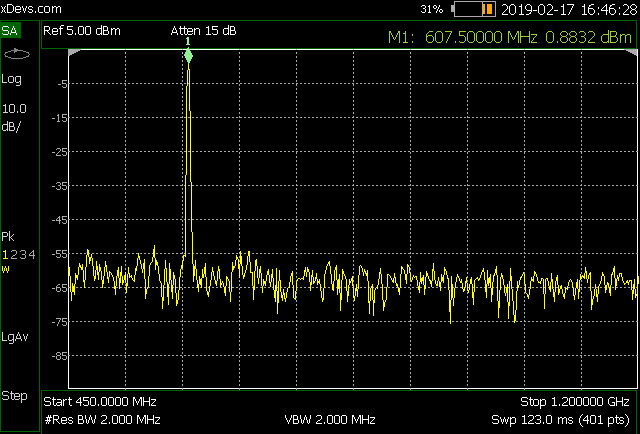
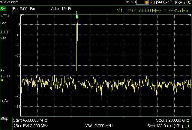
Green blocks I tested and they seem to be happily working, at least I couldn't find anything wrong. BAND1/BAND2 selects which VCO will receive power and begin operating. When generator programmed to use BAND1 I can detect and see stable RF signal before and after the VCO buffer, using my freshly received spectrum analyzer.


However when I get any frequency programmed to use VCO Band 2, i get some crap out instead of clean tone:


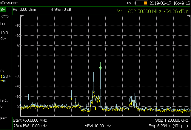
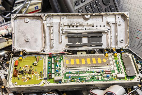
Here's the module itself:


VCO module PCBA in question:


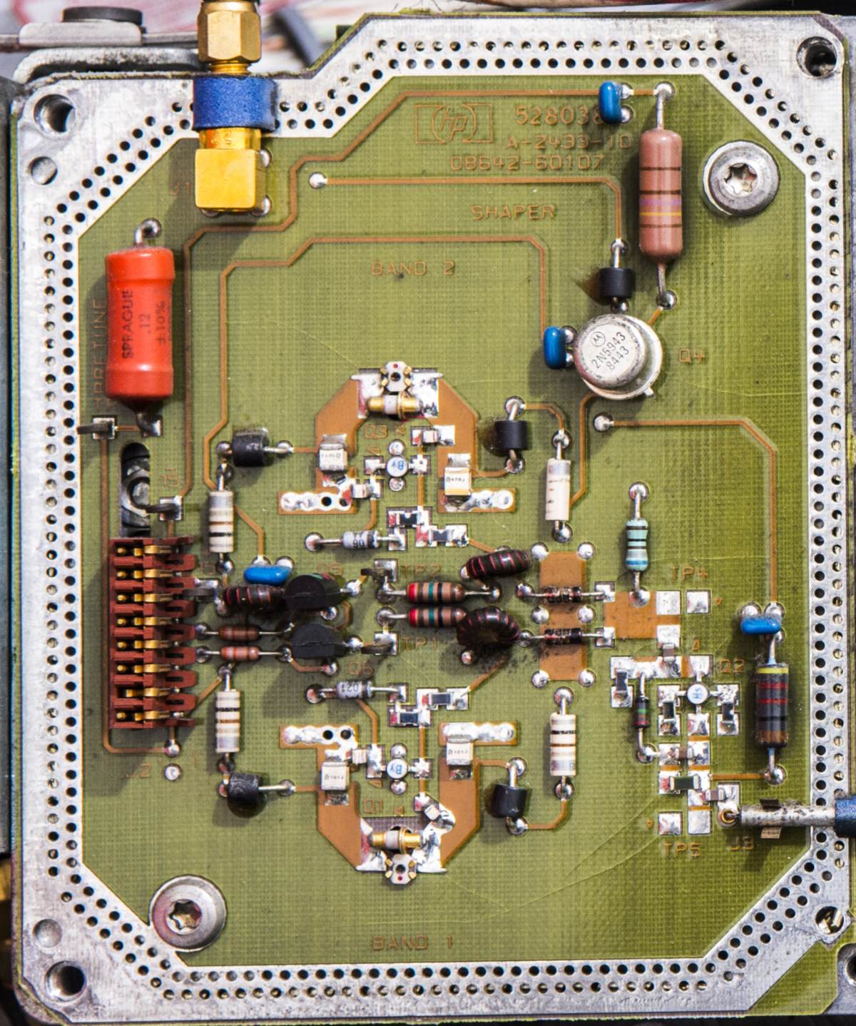
I don't have any RF parts to try, so didn't come with any better idea than to swap RF NPN transistors between each of the VCO. Hopefully I can see issue to follow the transistor? All resistors and zeners checked out okay.
YouTube | Metrology IRC Chat room | Let's share T&M documentation? Upload! No upload limits for firmwares, photos, files.
 

Offline picburner

  • Frequent Contributor
  • **
  • Posts: 497
  • Country: it
Re: Restoration : HP 8642B SigGen
« Reply #7 on: February 18, 2019, 11:22:01 am »
TiN is an optical effect only or the pcb 08642-60107 (last picture below) has many cracks?
 

Offline TiNTopic starter

  • Super Contributor
  • ***
  • Posts: 4543
  • Country: ua
    • xDevs.com
Re: Restoration : HP 8642B SigGen
« Reply #8 on: February 18, 2019, 03:12:40 pm »
That's not optical artifact, it does look like crack, but seem to be just soldermask issue.
And transistor swap didn't do anything, still same issue with unit. I'll need to rethink what to try next.
YouTube | Metrology IRC Chat room | Let's share T&M documentation? Upload! No upload limits for firmwares, photos, files.
 

Offline SilverSolder

  • Super Contributor
  • ***
  • Posts: 6126
  • Country: 00
Re: Restoration : HP 8642B SigGen
« Reply #9 on: February 18, 2019, 04:07:00 pm »
I realize belatedly that the original post is years old, but I'll leave this here for reference anyway!

Those switches seem to be the (in)famous "Bill West Switches".

They work by S-bending a little spring strip when you press a button down.  When you release, the "S" bend straightens back out again and pushes the button back out.

As long as the springs haven't rusted, they can be made to work again by pulling out the spring from each switch, clean the area where the spring lives, and apply a light coating of a plastic safe lubricant to the spring on reassembly.

Look for cracked/borderline solder joints under those switches and their accompanying LEDs.  It can appear like there is something wrong with the controller/ switch matrix scan circuit, but every time it has turned out to be these solder joints for me.  They can cause buttons to either not work at all, or work intermittently. The same is true for the indicator LEDs.  I guess the board is flexed a lot under the buttons when used over the years (decades!), promoting solder joint problems.

There is at least one thread here on EEVBlog about this,  search for "Bill West"...

« Last Edit: February 18, 2019, 04:13:12 pm by SilverSolder »
 

Offline SilverSolder

  • Super Contributor
  • ***
  • Posts: 6126
  • Country: 00
Re: Restoration : HP 8642B SigGen
« Reply #10 on: February 18, 2019, 04:38:40 pm »
Re the problem you are currently wrestling with - just thinking out loud, with my $0.0001 cents worth:

About an inch to the right of TP1 in your picture, there are what appears to be two diodes that appear to act as switches to "turn on" either Band 1 or Band 2, driven by the transistors on the left.   Does the signal look clean going into the diode for Band 2 (left side of diode)?

Do the voltages on TP1 and TP2 look the same, when Band 1 vs. Band 2 is switched in respectively?   Even if the voltages do look reasonable could the diode itself have gone bad in some way, causing it to not conduct as it should and do strange stuff to the signal?


Share me

Digg  Facebook  SlashDot  Delicious  Technorati  Twitter  Google  Yahoo
Smf