I think I may have found it (and I hope that is true.)
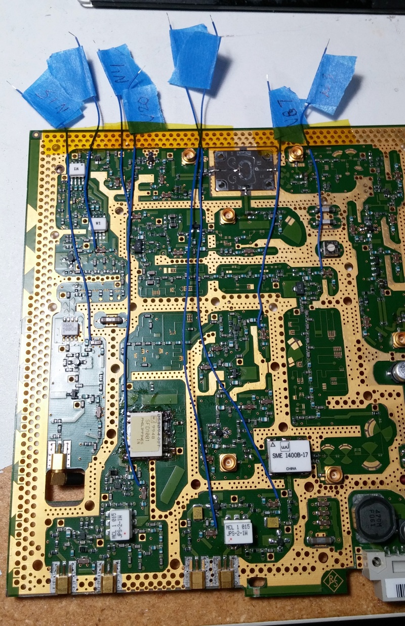
Since the last update, I've slacked off a good bit, it's been somewhat more difficult to get moving on the project after a month and a half of testing, but I managed to tap into the DC bias lines for essentially every remaining RF amp in the signal path (not including the ones that are part of the split filtering, since the problem exhibits in every frequency band). I tapped things off in my standard location, the edge of the capacitor that's two inductors out from the signal path, that is not hugely isolated from the main power rail, but is enough to be able to see some changes on a sensitive instrument (and I've been using a 6.5 digit meter).
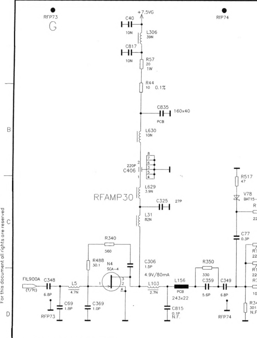
I measured bias voltage from "pin 1" of C406, and equivalent places in other DC bias lines elsewhere in the circuit, the amps almost always have this 3 inductor, 2 capacitor lead in to the RF path.
I noticed that I'm oddly comfortable working on this board now... the first couple days I was careful not to get fingerprints in unknown areas and only handled it by the edges.... but while I don't think I'm manhandling it now, it's really just another board. The mystic qualities of RF design are gradually clearing to give me a more realistic picture of what should and shouldn't be done.
Here's some readings (I'll collate them in one post when it's eventually fixed so later attempts can have some references from my unit and because they are so far off of what the schematic says...):
N38 - 4.913V, somewhat noisy
N39 - 4.906V, somewhat noisy
V20 - 4.457V, somewhat noisy
N15 - 4.537V
N17 - 4.513V, "chunky" noise (similar amplitude, but slower changing)
N4 - 6.612V-6.601V, varies with frequency *NOT TO BE TRUSTED AS A WORKING VOLTAGE*
N3 - 4.72V-4.69V, gradual drop as it warms up
V87 - 4.423V, varies with level adjustment
And I got them in the unit and started testing. It really is tricky to capture one of the big instability spikes as you'll only get a few per power on and you have to let the thing cool down quite a bit between attempts, but I've gotten reasonably comfortable testing for it and can identify when it's likely on the way just from the fluctuations in output power. I got through most of my test points without any really notable instability (some, to varying degrees, but nothing with a direct correlation to the output spikes) until the third to last one, the SCA-4 amp at N4. After power on, pretty much every amp seems to settle down a little in voltage as the unit warms up and the output power increases (since it always starts out of range for the ALC), but this amp seemed to settle more... instead of a few millivolts, it was closer to 10 millivolts, and as the curve started to flatten out as it had warmed, you could see noise creeping in... and this was about the same behavior that the output power showed. But after two attempts with some cooling time on either side last night, I was unable to get that output power spike to be sure. Today, after hours of being powered down, I gave it another try and after several minutes of warming, I captured this:
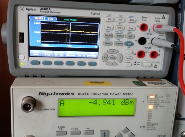
Relatively stable after the voltage had settled, a gradual but noticeable rise in voltage as the output level started to go up (a ramp up that has characterized every spike I've seen), and then a sort of asymptotic drop at the instant the output power came good - but only for an instant. The smaller ramp after it is actually another momentary jump, but the output power didn't get as high.
Not only is this the sort of output behavior that I expected from the faulty amp (though i would have expected a ramp down with increasing current draw before the asymptote), but it's a behavior that directly correlates to changes in output power, which no other amp has really shown. Not only that, but N3, an identical amp chip that is upstream in the signal path from N4 and which is on the same power rail does not exhibit this behavior
at all.
So then how to source the part? The Sirenza SCA-4 is not easily available, and actually shouldn't be run anywhere near the voltage I measured

Well, luckily, it's been asked here before:
https://www.eevblog.com/forum/repair/replacement-for-sirenza-microdevices-sca-4-mmic-rf-amp/ and it showed up on google in this app note too:
www.go-gddq.com/down/2012-04/12041622014586.pdf The app note doesn't specifically mention that the SCA-4/14 is a Sirenza part and I haven't seen the /14 marking before, but the gain graph they show looks like a match and the replacement component probably would do the job.... if that one was available

So, back to the previous forum recommendations, I ended up ordering two amps from Digikey, the MMG3012NT1, which says it works to 6GHz though the graphs only go to 4GHz, and the SBB5089Z which is fully graphed in the datasheet. The SBB5089Z is twice the price, but is a more exact match, even the power requirements... but the portion of the circuit is still in synthesis, not at the full output frequency and since the MMG3012NT1 also supports higher input voltages, I figure I will try that one first.
I put my order in at about 3pm eastern time and Digikey's turnaround seems to be good, as I've already got shipping info. I think that means I'll be able to install the replacement on Saturday.


