If it comes to that, I may actually have a reasonable solution. Though the connector has two rows of pins, only one is populated, so using basic 0.1" header cables would be sufficient, then I've got SMAs for the output connections... would just need something for the LO connections, are they SMPs? The little snap size, but not the really really small ones you get on wireless cards.
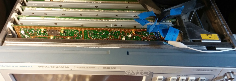
Anyways, it's progressed a bit, and while it's still obvious something's going wrong, I feel like I'm not confident enough as to what as to order a part yet. Also interesting is that I figured out what that tarnish was.... I actually sort of knew from first glance, but I expected milled aluminum shielding, so I dismissed it. They shield blocks are silver plated, probably magnesium alloy. The tarnish is the exact same color as silver tarnish and silver tarnish comes from air exposure. It's also an extremely bright looking metal, notably lighter in color than some milled aluminum i had near me and it has a sort of distinctive look, looking at an unpolished silver plated cavity always looks especially bright to me (and I've actually seen it dealing with musical instruments). Anyways, the LCD and front panel are also a distinct module with a fan in back... and the fan is close to the two holes for the adjustment pots, explaining the more significant tarnish.
On the note of the fans, I tried disconnecting the main one to see if replacing it would quiet things down, and the two others are much quieter so it should help, but instead of throwing an error, when it doesn't sense the fan it just turns off partway through booting and can't be turned on again until several seconds with the main power off. A little surprising, and since the new fan is 1000rpm slower or so, I hope it doesn't end up being a problem when installed.
As for the actual testing, I hooked up some mod wires and put the card back in nude. The board flexes more than I expected, mostly because the fitting is tight, and when I got it hooked up.... it was unhappy. A new error cropped up when restarting it, a 2.4GHz LO unlock error on an entirely different board. My thought was that the lack of shielding between different inputs picked up so much noise that it was going back through the LO cables and messing with the PLL on the other board. Thankfully after returning the RF side shielding, the error is gone.
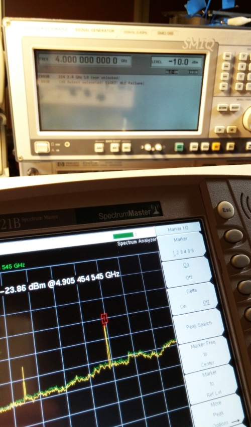
Checking the wires I had put on, the voltages on the ALC amp were fine, the DAC worked fine (nice little steps that reset with every attenuator click), and there was definitely signal on the detector output. The ALC output was a bit tricky to figure out, and thanks to the LO error, the frequency was roughly 1GHz over what it was set to and 10dB down from where it would have been... so I figured I would replace part of the shielding, pick a few other spots, and try for better data with another one.
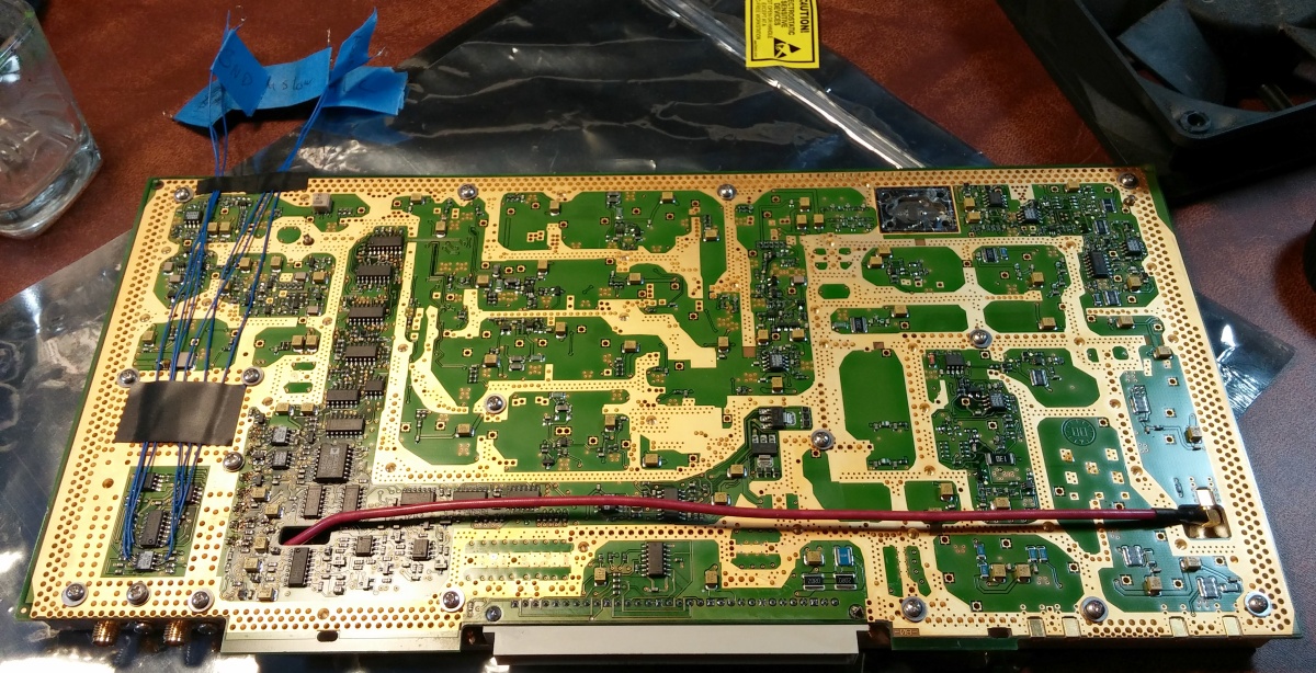
So I took the card out, reworked the mod wire placement (watching the inverting input, the output of N29, and the control lines for D9), and stuck half the shield on. The screws around the power module mostly go in without the other half, but none of the others, and I needed more structural support to feel comfortable sliding it in again... so I went through my little screws and got about a third of them redone just on the board - trying not to torque it down too hard and using washers, I would have preferred nylon washers to be sure not to mar the gold, but I didn't have enough. Anyways, it worked well, slid in better, and gave me a much better test (no more LO error).
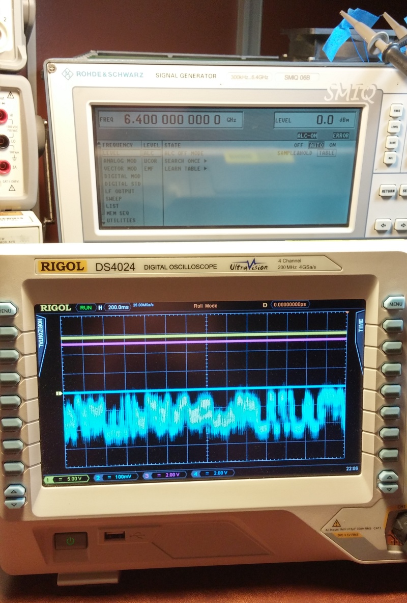
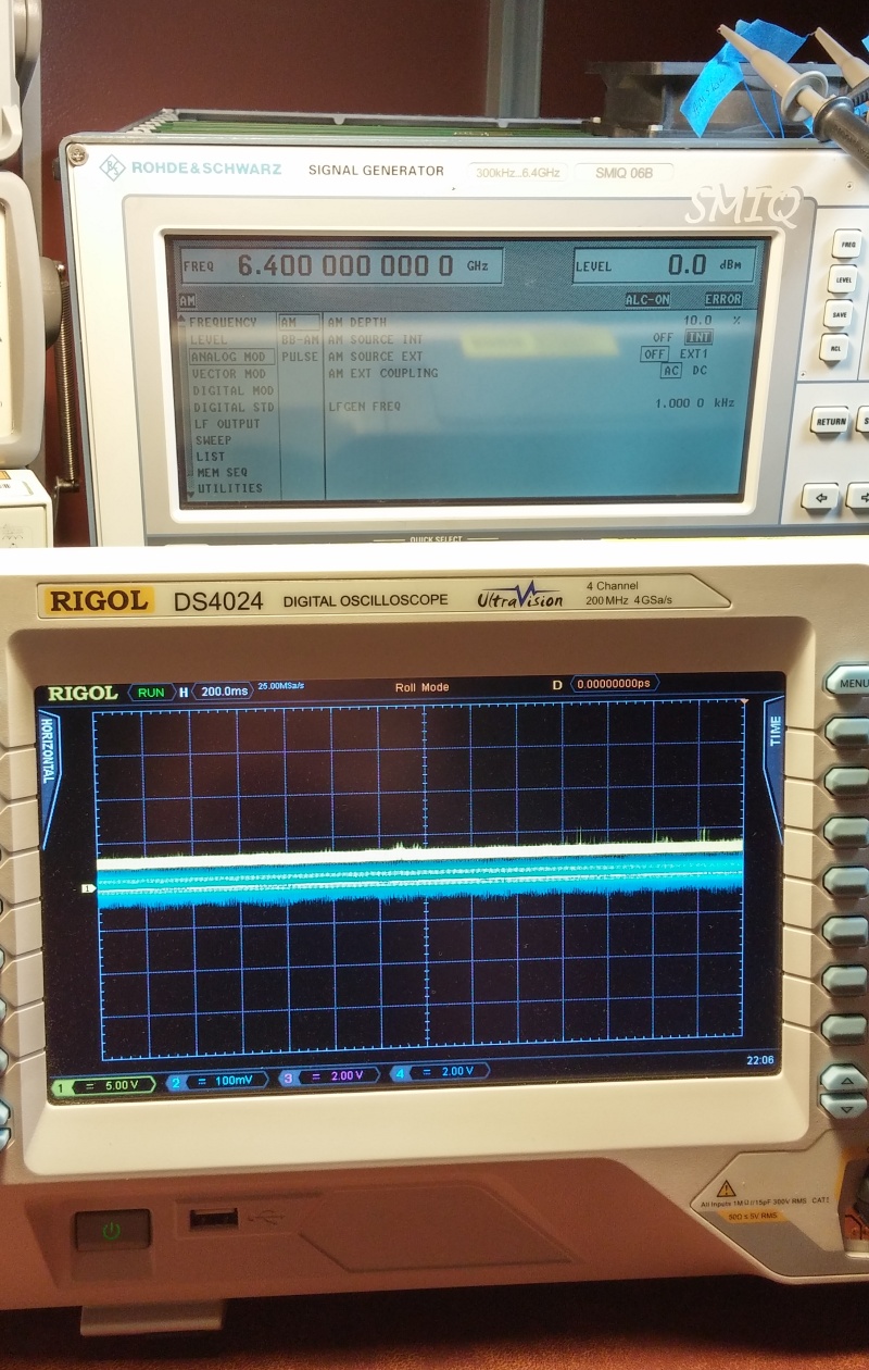
I found the switches to be switching properly (though I'm still not 100% as to what KLEMM does is for, it just seems to bias the input towards 10V and switching ALC modes doesn't change the bit), and in certain stages the amp seems to work just fine... but then sometimes it just slams to the upper rail regardless of the detector input, which should always be influencing the ALC. It defaults to sample and hold mode for the ALC, which works fine in modulation mode but looks horrific in normal mode. Since it actually looks wonky in AM mode but the output is fine... it makes me wonder.
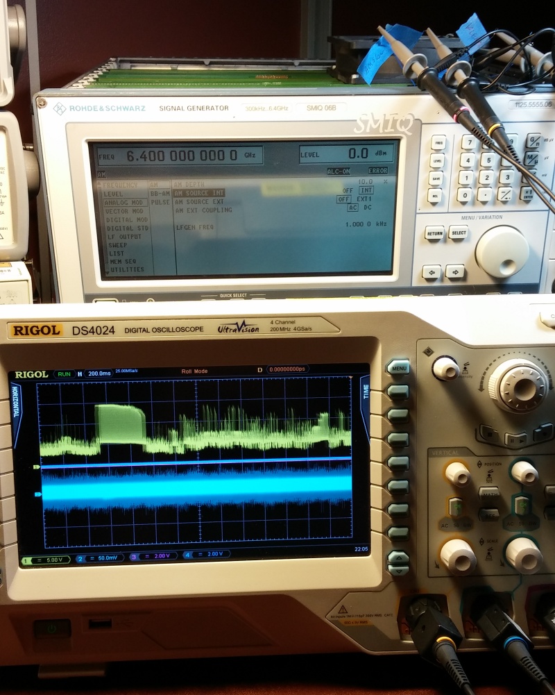
Then moving to the table mode (which isn't properly set because it fails the table learning self-calibration), the output locks high in standard mode despite the detector going crazy (an amp not performing well enough or intermittently?), but then you switch to modulation and the whole thing seems to be fine.
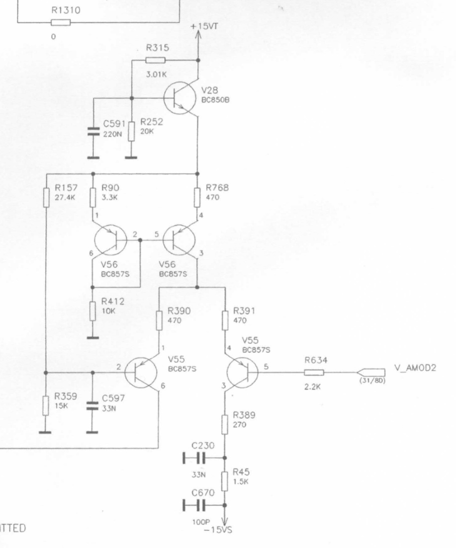
So I'm going to take a bit to think things through again and read the schematic over again. I found that this circuit doesn't actually drive the final stage amp, that one seems to be fixed, but it does drive RFAMP20 and 21 (a fet and an IC rated to 3.3V and 6GHz operating at 3.4V and up to 6.4GHz.....). I was thinking maybe the opamp making up the ALC isn't able to source enough current to operate the stages in some situations... but even if the gate was shorting out in the transistors that it runs, there would still be like 4.5k worth of resistance to get through the gate on either V_AMOD channel and the positive/negative voltage source they control do work in at least some situations. This is the circuit that converts the V_AMOD output to a bias voltage for the RF amps in the signal path.
I was looking to see if some of these parts could still be sourced, and it seems like most of them still can, but even things like the final stage output amp are rated under the spec of the instrument - the bare die is rated to 6.5GHz, but the packaged version used is only rated to 6GHz... then those 3.3V 6GHz amps are used repeatedly at 3.4V according to the schematic. I don't know if parts with that performance were just real hard to come by around the turn of the millennia or if they were trying to keep the price down, but seems like strange choices to me.


