Author Topic: Rohde & Schwarz UPV Audio Analyzer - teardown and repair  (Read 8166 times)

0 Members and 1 Guest are viewing this topic.

Online DaJMastaTopic starter

  • Super Contributor
  • ***
  • Posts: 2298
  • Country: us
    • medpants.com
Rohde & Schwarz UPV Audio Analyzer - teardown and repair
« on: March 12, 2019, 05:57:36 am »
A few months ago I got my hands on a non-booting R&S UPV audio analyzer, and I eventually got it running well.  Since it's a rarer (expensive) piece of gear that's of interest to some, and since the repair techniques/info could actually be pretty useful for fixing up other R&S gear of similar age, I figured I'd document it a bit.  I lost some pictures from early on when I got it (phone died), but I've got some of the especially tasty sections.

When I received my unit, it wouldn't show anything on the front panel or screen and if left powered up for a bit, would sound a two-tone beep with the fans going normally.  It was an older unit loaded with the 1.4 version firmware and one hardware option, a second generator so it can generate multitone signals.  I went to check voltages and had a bit of trouble, because the power supply layout is actually pretty interesting.  It has a mains power switch with no standby (this is actually important later in the repair), but has a linear supply board with a nice big toroid transformer in a metal can with separate taps for every voltage rail.  On the linear board, each of those taps has its own discrete diode rectifier and then a linear regulator - a bunch of 7800 series included!  What's unusual about it is that the taps/rails are grouped into two groups, each with a common ground, but not all linear rails share a common ground.  I didn't trace them out extensively, but I believe there is one set for the generators and one set for the input section.  Then there's a pass through for the full mains voltage and an SMPS power supply for the digital section right behind the front panel.  The analog board on the bottom has very distinct power planes, the input sections are isolated, the rest of the board is mostly the second analog rail set, and then the connectors that go up to the top meet optoisolators as soon as they hit the analog board.

The screen on my unit didn't turn on, but upon opening it up, I found it was just altogether missing the backlight inverter.  The installed screen was a Toshiba LTM08C351S (8.4", 800x600, 6 bit color, LVTTL interface, CCFL backlight), to my surprise, since it's the same screen used in a similar vintage Advantest spectrum analyzer I've worked on, so I ordered a replacement inverter, the ERG 8mAD3407.  The inverter worked great, but either because I mis-connected the enable pin or because it wasn't used originally, when the unit is on but the screen is not being controlled (right at the start of the boot sequence), it appears white, since the backlight is on all the time.  This didn't make it show anything on the screen though, so I dug around for beep codes after finding out it was coming from the buzzer on the CPU board.  The FMR6 CPU board it used has a Pentium 3 mobile processor and while it has a memory slot, it has soldered down RAM and no CPU socket, so it's pretty much as is.  I narrowed down the BIOS manufacturer looking through some R&S boot screen images and found the two tones indicated a CPU error of some sort.  R&S didn't have a firmware available to try to desolder and reflash the BIOS chip, and the CPU isn't something I could locate, so my option sort of came down to reflowing the chip and praying, though I was sure the performance wouldn't be spectacular if I got it to work (1GHz PIII and 512MB of RAM).

So I got an odd idea in my head... what if I transplanted a different CPU board from another instrument into it.  Looking at R&S upgrade kit information, I found FMR9 and later boards indicated as being used with UPVs, and through looking at some info screens from other R&S gear, I found that the CMU200 sometimes used an FMR6, as well as the FSP.... and the AMR200.  The AMR200 isn't that popular because it's only a baseband generator, but I could get a functional one for about the price of just a different FMR board, so I found it had an FMR9 board in it and took my chances.  The FMR9 board in it is a 1GHz Core2Solo class mobile processor, and the memory module was upgradable to 2GB - a nice improvement over the PIII.

I knew the board worked, but the sockets were slightly different... the FMR6 has 3 large downward facing sockets, the FMR9 has two of them, omitting the one farthest from the front panel when mounted in the UPV, but includes a smaller one between those two, which is left unconnected on the AMR.  I removed a standoff on the UPV's topside digital mainboard and connected up the new FMR9, and I had a boot!  Turns out, the large connector closest to the front of the instrument in the UPV is power, system communications, and back panel computer connections, the second big connector is the PCI bus, and the third connector, omitted on the FMR9 but present on the FMR6 is the ISA bus - which isn't used by the UPV mainboard!  I swapped over the USB connectors and cable to the UPV (the UPVs were just a little short for the new board's connector location), but the rest of the pieces fit back together.  The AMR200 used the small display connector but still had the larger pitch one that drove the older display (the AMR200 uses a similar 8.4" 800x600 display, but with more color depth and a LED backlight, unfortunately with different mounting holes, so I didn't carry it over.)  The UPV runs Windows XP, as well, and since XP does not generally play nice with SATA drives without slipstreamed drivers, I was unable to get the original disk to boot with the new board, but I was able to copy the AMR200's disk image to an SATA SSD and get to boot all the way into windows.  Then you just uninstall the AMR firmware and install the current UPV firmware and I could make a measurement!

Unfortunately, after installing the UPV firmware, it rebooted..... and didn't come back.  After some time poking around trying to figure out why the CPU board's voltage regulators weren't being turned on (I thought I had goofed something up), I eventually got the bright idea to connect the AMR's front panel flat flex cable to the board, and I was able to get it to boot.  As it turns out, the CPU board defaults to running on an ATX power supply (the AMR has a soft power key) with a standby supply, so the manual power switch in the UPV never triggered the soft power and prevented it from booting beyond that first time.  Switching to AT power supply mode in BIOS let it boot normally with the physical power switch.  I was then faced with another problem, the front panel didn't seem to work all the way, and some buttons seemed to be mapped to the wrong things.

With some investigating, I found that the hotkey mappings for the front panel were almost entirely wrong, and while there were drivers labeled "FMR6 FP" in the current UPV firmware, force-installing them lead to a bluescreen, and the chip interfacing with that front panel flat flex is different on each board, but when windows auto-detected them, it just identified the front panel buttons as a standard HID keyboard.  So I contacted R&S support and asked for an older firmware, hoping the drivers for the older system were in there and having heard that you at one point needed to upgrade to 2.x from 1.x before moving to later versions (not sure that's actually true, now), and was told that it likely wouldn't work because the CPU board is keyed to the instrument type it's in.  An uncharacteristically bad design choice from R&S, imo, but it appeared to be true.  I started looking into key remapping software to get it running with the HID keyboard driver and found that every key on the front panel was actually being read, so it was at least theoretically possible to remap them.

I tried several programs which couldn't distinguish between keyboards and would also remap your normal attached keyboard keys, then found a program touting multi-keyboard support and working initially only to have it ignore modifier keys for some reason when I finally finished the remapping script... but I eventually found a combination of interception ( http://www.oblita.com/interception.html ) and intercept.exe (described here https://github.com/TaranVH/2nd-keyboard/tree/master/Intercept ) would do the job.  I made the remap with tue UPV manual's keyboard shortcut key table, very helpful since it gives you the hotkey combination for every front pane button, then made a couple special modifications.  For the Escape key on the front panel, you can't map Escape to something in Intercept because it uses the character to end recording what keystrokes you want to map - but you can add the scancode to the .ini file after it's been defined as an empty macro!  I also found that the Window arrow keys in the Data section would undo their move every time the key was released, making them useless for navigation... but this turned out to be the timing of releasing the Ctrl key - if you release it last, the choice resets, but if you release it before Tab, it stays on the new selection.  I had a working front panel again, wrote a batch file to run the application when the instrument boots, and I've attached my key remapping .ini file to this post.

While that completed my repair as, best I can tell, everything seems to work, I wouldn't try to use this instrument with just the front panel controls.  You really want a mouse and keyboard to navigate through all the menus and windows in the interface... maybe for running predefinied tests it would be fine, but setting up every parameter with the front panel is pretty tedious.  In any case, here's the part you came for:


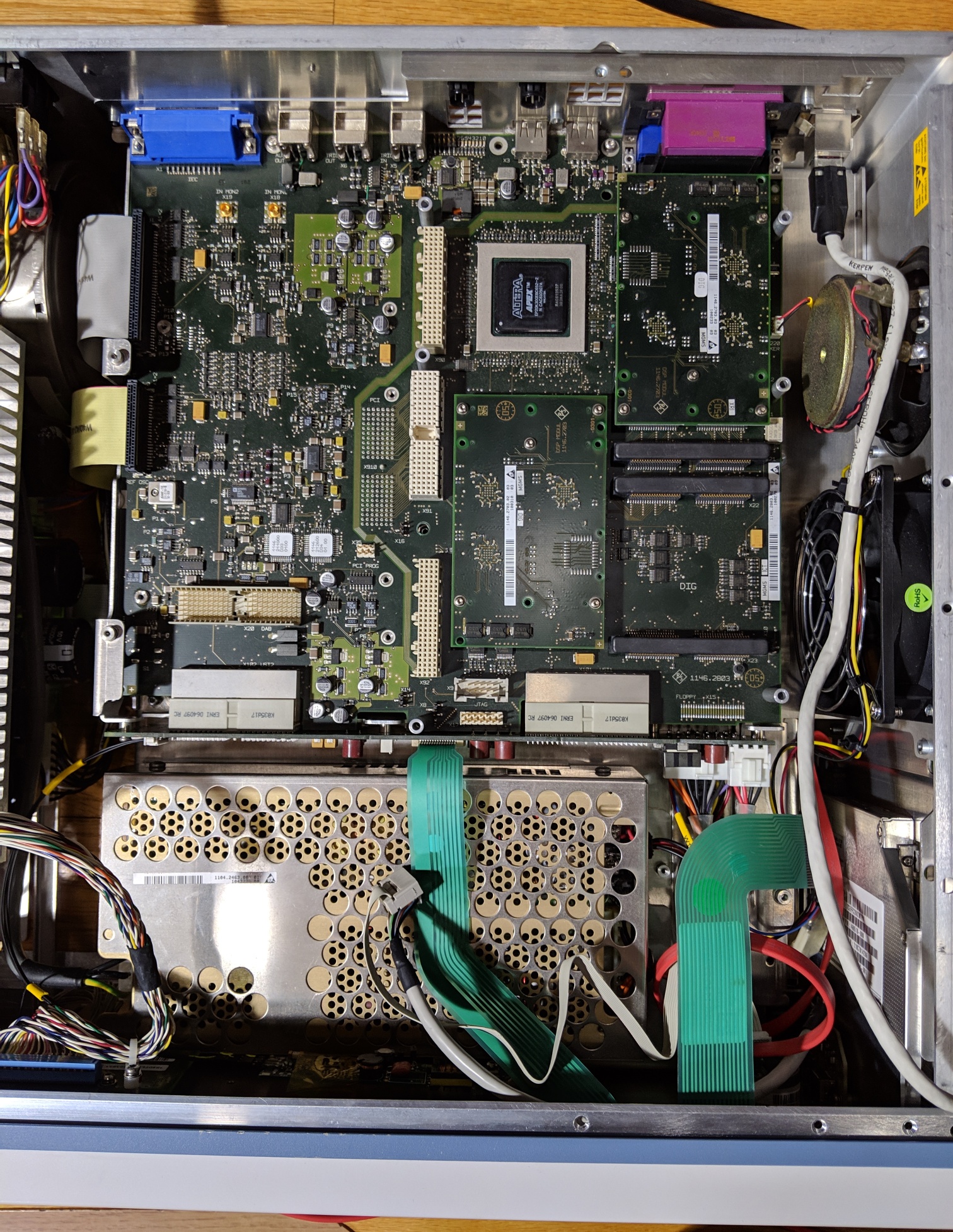
The main digital board in the UPV - top side, the CPU board would connect over the DSP modules on the right side, the front panel is down.


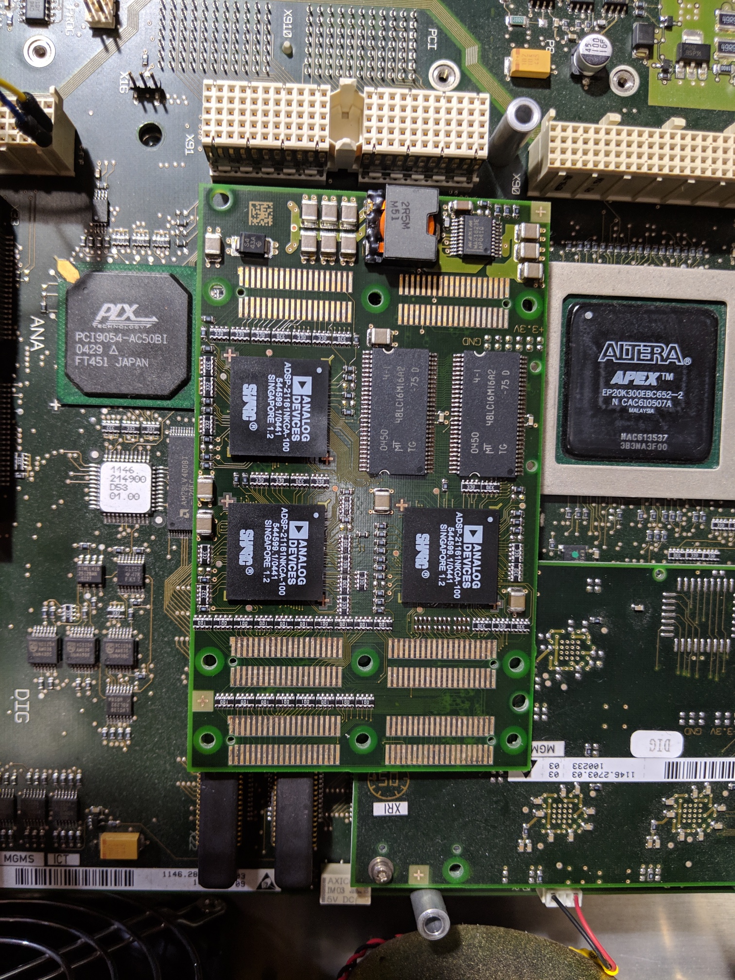
One of the DSP modules (the other has one fewer DSP chip on it)


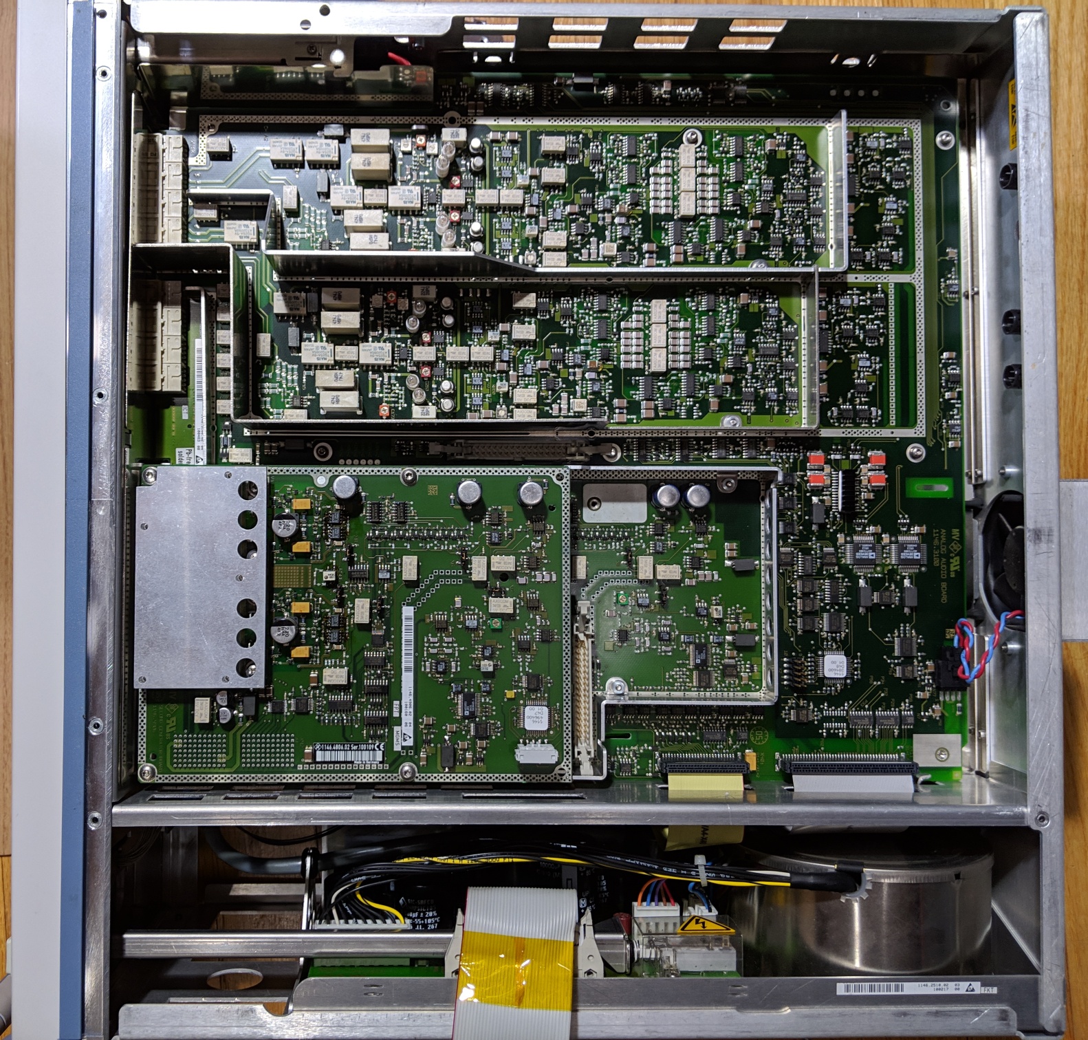
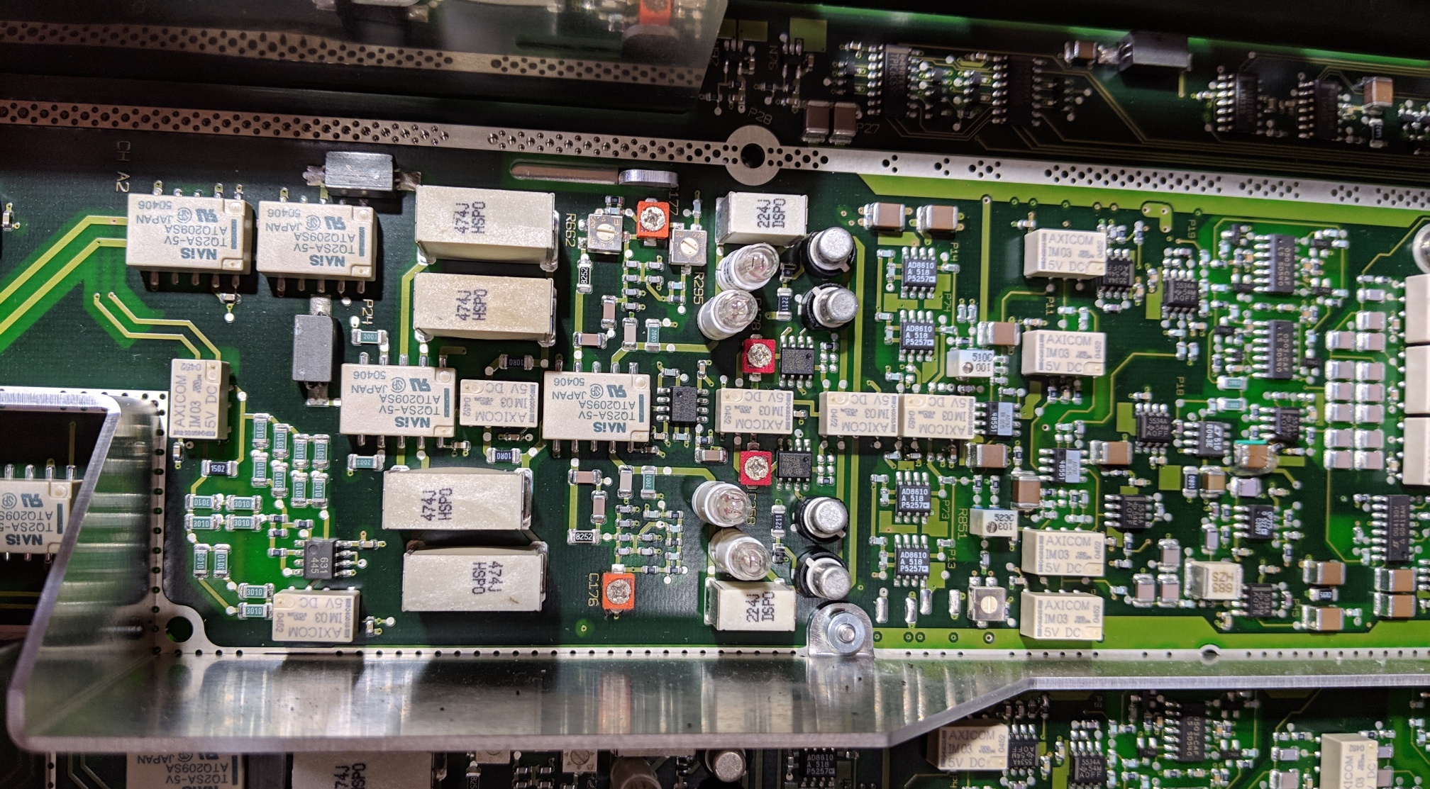
The analog boards under the bottom cover, the linear PSU is down, the long narrow areas with shields are each input channel, the metal can is over the generator (actually the second one on the option board).  The kapton tape is my addition, there was some wear on the ribbon cable where it went over the metalwork.


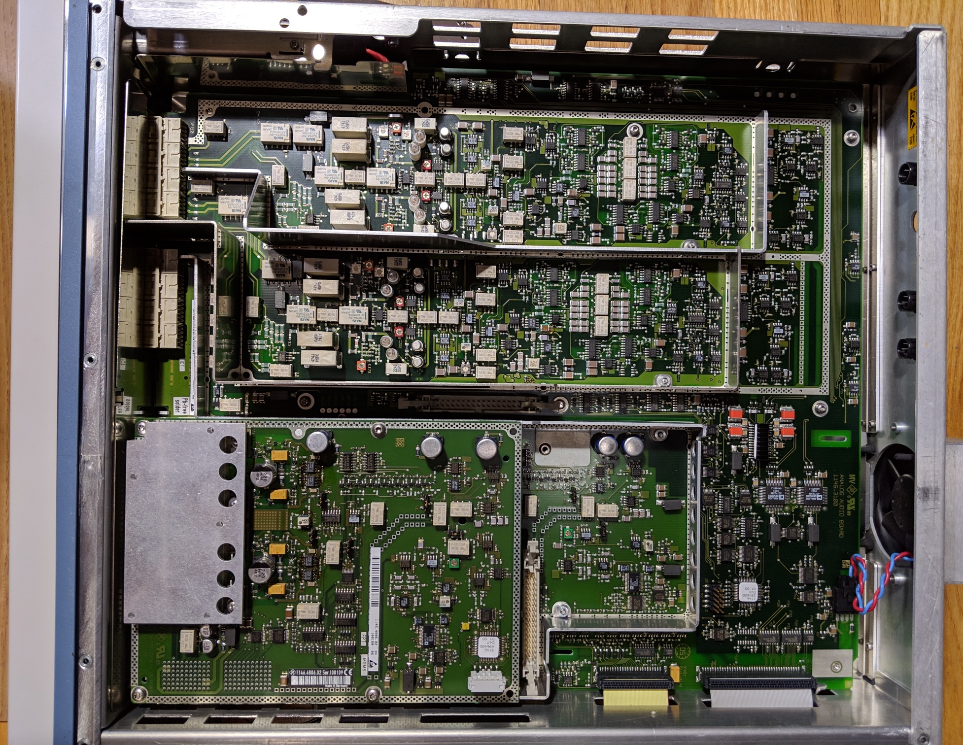
Same view, zoomed in on the analog board a bit.


Channel two's input section.


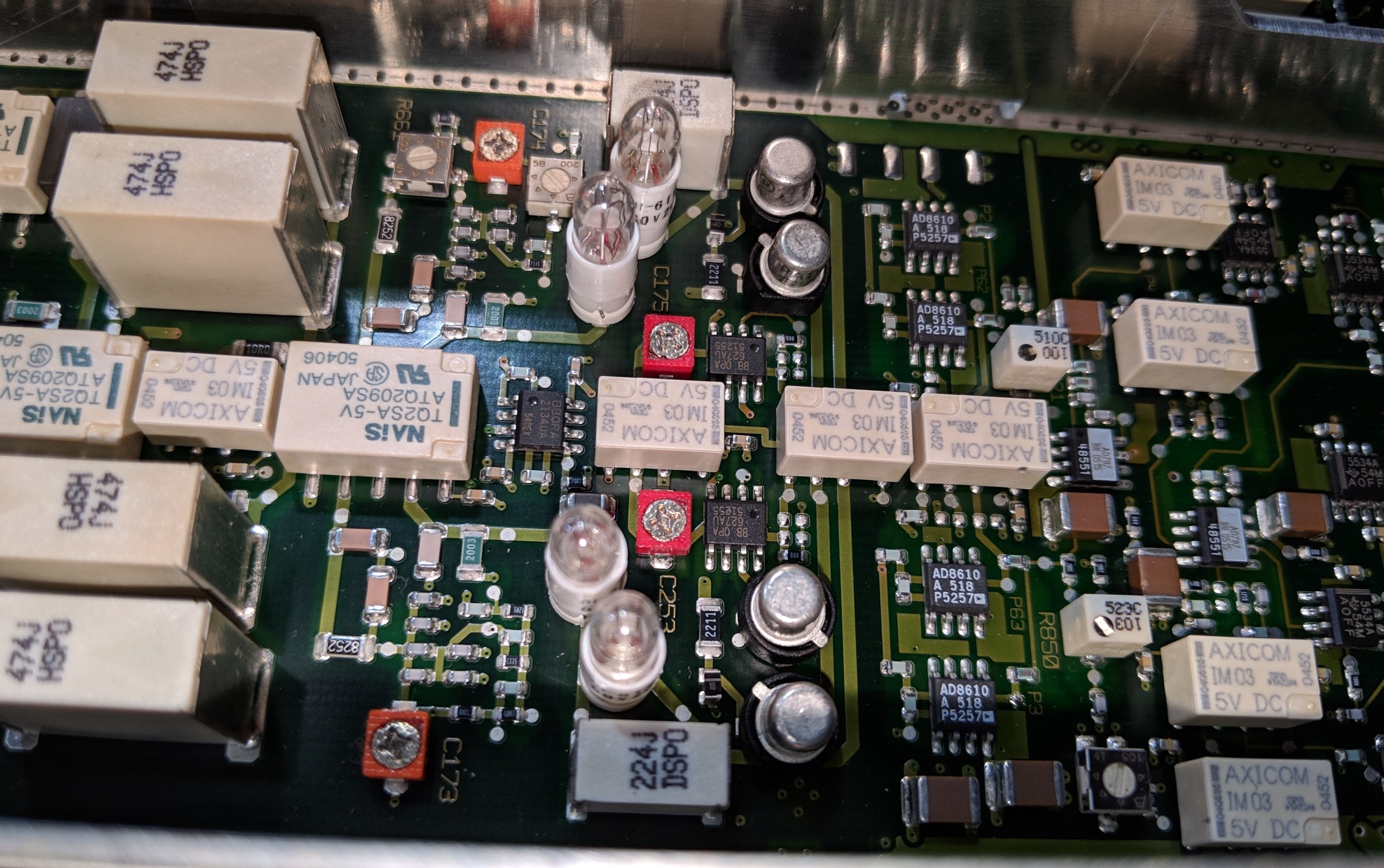
Zoomed in on channel one's input section


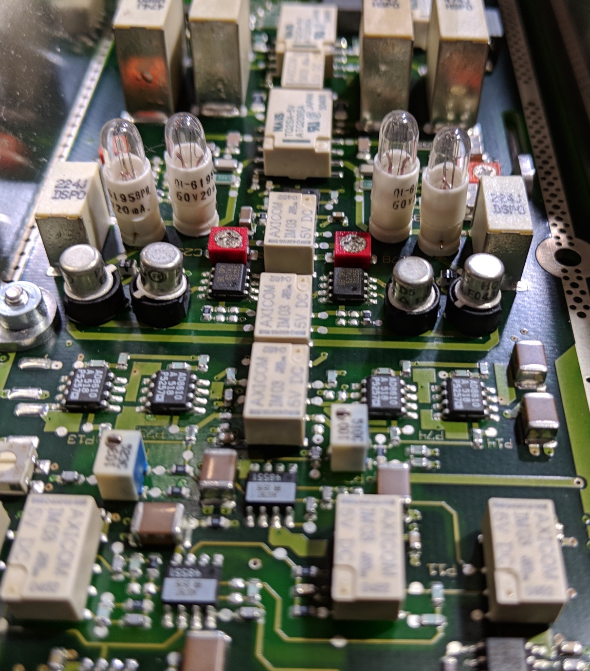
Input protection, you're seeing that right, 4 neon lamps per channel.


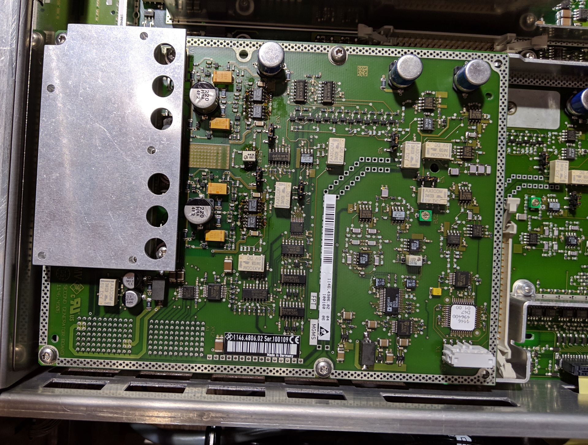
The second generator option board, very similar to the main generator located directly under it.  The DAC and generator frontend is the only fully shielded thing in the instrument (aside from the linear PSU's toroid, I suppose).


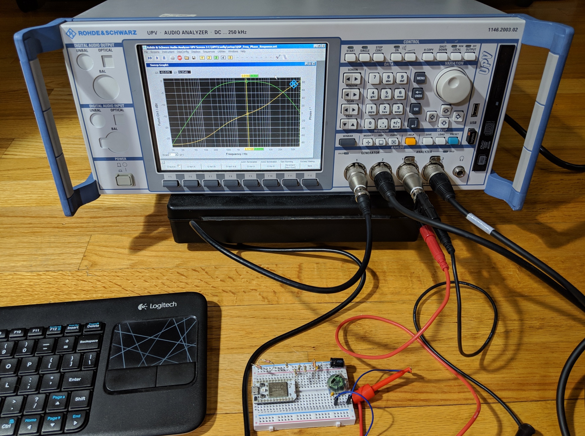
Happily measuring an inductor in series with a 1uF cap, green is amplitude, yellow is phase - looks like a VNA to me!


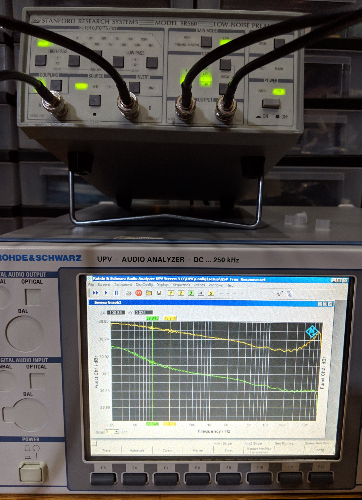
And verifying the low frequency gain linearity of an SRS SR560 - full scale on the graph is 0.1dB!
 
The following users thanked this post: thm_w, KE5FX, LoTech, RLMCN, D Straney, Smoky, SES Audio, c1ferrari

Offline Edwin G. Pettis

  • Frequent Contributor
  • **
  • Posts: 451
  • Country: us
  • The plural of anecdote is not data.
Re: Rohde & Schwarz UPV Audio Analyzer - teardown and repair
« Reply #1 on: March 12, 2019, 04:22:00 pm »
Those four lights are incandescent bulbs not neons, they are likely in the oscillator circuitry, classic circuit.
 
The following users thanked this post: SeanB

Offline Zucca

  • Supporter
  • ****
  • Posts: 4308
  • Country: it
  • EE meid in Itali
Re: Rohde & Schwarz UPV Audio Analyzer - teardown and repair
« Reply #2 on: March 12, 2019, 05:05:59 pm »
Outstanding!

Look how much $$$ you saved:

eBay auction: #323662965779
Can't know what you don't love. St. Augustine
Can't love what you don't know. Zucca
 

Online DaJMastaTopic starter

  • Super Contributor
  • ***
  • Posts: 2298
  • Country: us
    • medpants.com
Re: Rohde & Schwarz UPV Audio Analyzer - teardown and repair
« Reply #3 on: March 12, 2019, 05:17:53 pm »
I don't know how they go for so much.... though I guess R&S still sells them new with Windows 7, so there's that.

They may be incandescent, but definitely not in oscillators - those are the input channels, and their positioning is right after the range switching near the first set of amplifiers, since the frontend is rated to +-110V, it's gotta be input protection.


Couple things worth mentioning that I forgot to mention before:
The CPU and chassis fans were sort of loud initially, which I think is just silly with an audio analyzer, so I replaced both to good effect, though the chassis fan in particular is a pain because the power connector for it is hidden under the CPU board overhang.  The little fan that protrudes from the rear of the chassis is silent, though, and I've worked with a couple R&S instruments with a similarly sized/placed fan that have also been silent - good choice of that one!

I believe this motherboard swap trick will work with a lot of R&S instruments, since there is a wide swath of their instruments that use at least somewhat compatible CPU boards, so it could be a viable technique to fix spec ans and the like, of course I can't guarantee it  ;)

Also, those BNC to XLR connectors I used are not R&S original, they're Neutrik NA2MBNC and NA2FBNC connectors.  They work great if you need the single ended BNC output, the analyzer has no complaints, and they are durable/from a reputable company.  Saves a few hundred bucks over buying a set of 4 from R&S!


And another thing, I designed some rubber bumpers for the feet on the unit, they don't look like much printed in white (originals are light blue like the front handles), but they do the job! https://www.thingiverse.com/thing:3453904
« Last Edit: March 12, 2019, 06:36:25 pm by DaJMasta »
 

Offline nearmitech

  • Newbie
  • Posts: 1
  • Country: in
Re: Rohde & Schwarz UPV Audio Analyzer - teardown and repair
« Reply #4 on: July 23, 2020, 01:06:02 pm »
Hi,

First of all great post and thank you for a detailed write up.

Would you be able to indicate what sort of supply voltages I need to check for a blank screen?
A few days ago when I turned the instrument on the screen would occasionally flicker. The 34 way ribbon cable at the bottom from the power supply unit seemed defective and I suspected it was either that or a lose connection. Once it comes on it used to work flawlessly.

Today however, I replaced the 34 way ribbon cable but the instrument is dead. When you power it on the DVD LED flickers initially for a fraction of a second, all the three cooling fans are ok indicating that 12V supply is okay. However, after the initial LED indication on the DVD reader, the DVD tray does not open when you push the button. This coupled with the fact that the screen is dead leads me to suspect that its one of the voltages that is absent.

Any help would be much appreciated.
 

Online DaJMastaTopic starter

  • Super Contributor
  • ***
  • Posts: 2298
  • Country: us
    • medpants.com
Re: Rohde & Schwarz UPV Audio Analyzer - teardown and repair
« Reply #5 on: July 24, 2020, 05:11:32 am »
It sounds kind of all over the place, but a good starting place with a flickering screen is the backlight.  The module has high voltage coming out of one end, but it should have 12V and a 5V enable signal on the other, and if you can probe on the 1.4kV-2kV or so on the output then that's an option too.

There are a few cables that connect up to the LCD, the one coming from the CPU board has the actual drive signals, the smaller ones coming off the front board that connects that top board with the CPU board on it to the underside and power supply, also make sure they're attached.  Then if you're not getting DVD stuff, it may be useful to try looking for signs of life on the CPU board, and maybe try probing the voltage on the rails for it.  I think normally DVD drives will still open if powered up, but maybe if the computer is talking nonsense on the bus it won't, so it's probably worth looking for bios lights or whatnot (I think there are some boot indicator lights towards the back?)

I've also had the dvd tray itself catch on the metalwork on the front, so maybe just try pulling it out a bit manually when you push the button to see if it's just getting caught.
 

Offline LoTech

  • Contributor
  • Posts: 13
  • Country: us
Re: Rohde & Schwarz UPV Audio Analyzer - teardown and repair
« Reply #6 on: August 20, 2020, 08:58:25 am »
Thank you very much for the in-depth write-up! Years ago I could only dream to own something like these, but as they age and became more "accessible" , I was able to get one.

Mine is a working unit, with an FMR6, restored the factory default, but it has the first version of UPV firmware and XPE with no service packs. I am looking to update the firmware and that requires I first update the XPE service packs. Upgrading the service packs turned out to be a nightmare as I keep running in all sorts of system install errors.

A real nice gentleman  8) sent me a copy of his UPV HD image but it does not have the XPE service packs installed, so I am back to square one.

The idea of having a more modern board is very intriguing as the old Pentium III and on-board RAM, is not winning any races.
The board you used as replacement; did it have the main connectors facing downwards or facing up? Did you have to do anything to those? Asking because a photo of a AMU-200a FMR7 shows the connectors facing up. Assuming the FMR9 you used would have been the same if coming from the same instrument ???

Also, since you have the more modern board, did you consider upgrading the OS to Win7?

These analyzers would be fantastic if not so interdependent of the antiquated PC hardware and windows software


Offline LoTech

  • Contributor
  • Posts: 13
  • Country: us
Re: Rohde & Schwarz UPV Audio Analyzer - teardown and repair
« Reply #7 on: August 20, 2020, 09:37:35 am »

They may be incandescent, but definitely not in oscillators - those are the input channels, and their positioning is right after the range switching near the first set of amplifiers, since the frontend is rated to +-110V, it's gotta be input protection.


yes, some sort of input protection. BTW, my unit had cold solder joints on two of those four .47uf coupling caps. One was bad enough to manifest problems when toggling between AC and DC for chanel 2, but I found a bad joint on the other channel as well, so I refloted all 4 caps.
 

Online DaJMastaTopic starter

  • Super Contributor
  • ***
  • Posts: 2298
  • Country: us
    • medpants.com
Re: Rohde & Schwarz UPV Audio Analyzer - teardown and repair
« Reply #8 on: August 20, 2020, 06:11:28 pm »
The AMU board had the main connectors facing down, just like the UPV.  The AMU and many similar instruments have the motherboard directly under the screen module in the front, so they use the back facing connectors on the bottom to go directly into the backplane that runs along the bottom of the instrument.  I had to remove one standoff from the UPV for the upgrade, since it would have obstructed the PCIe blade connector, and maybe the ISA connector was missing (I don't remember), but the ISA bus seems unused, so the UPV communicates through the PCI on the main connectors.

I never upgraded OS, between the faster processor (not a gigantic difference under XP, but the RAM doubling probably helps) and the SSD, the boot time isn't all that long, and the newer firmware's options fit fine and are complete in XP, so I just leave it as a standalone.  As with other XP based (and older) instruments I've worked with, it can be a pain to restore and upgrade, but it works all the same after that.  Supposedly Windows 7 can run on a pentium 3, but I wouldn't bother because performance will probably be abysmal.  I think my FMR6 board originally had 256MB onboard and a 256MB module installed, so maybe that could still be an option (I don't think it would work with 512MB, though, at least a lot of P3s run into this), and then I think I've done at least one regular windows XP pro install on this or another instrument and it's been fine.  If you get an install disk with the service packs already installed, it could fix it even if it's not the embedded version.  From what little I remember, it's more about stripping out some consumer features and things than it is about getting extra performance, the base install and the embedded version perform similarly in terms of boot time and in application.
 

Offline LoTech

  • Contributor
  • Posts: 13
  • Country: us
Re: Rohde & Schwarz UPV Audio Analyzer - teardown and repair
« Reply #9 on: August 20, 2020, 07:40:25 pm »
yes, I upgraded the one memory stick to 512MB, but the system still sees 512MB total, which I think is the embedded 256+ only 256 from the new 512mb stick??? can't tell, but adding the 512MB stick seemed to make it quicker on the bootup time...maybe just a placebo effect on my part.

so far, besides trying to upgrade the service packs on XPE and failing every time due to a memory error when trying to install the MSDE,

I tried to do a straight-up XP Pro with SP3 install and the machne crushed after reboot
Tried to install XP Pro / SP3 in parallel with the embedded and it also crushed after reboot, albeit, the XPE remained functional

I was hoping to find a UPV HD image with all service packs installed already, so I would not have to individually install the MSDE.

net, net, upgrading the service packs for XPE on this machine seems to be a nightmare. I am sure I am prolly missing something super simple, but for now I am stuck at this stage.

Thanks for clarifying the connectors orientation on the AMU200a.
The ones I have seen for sale have the FMR7 board, so I guess after a certain serial number they have the FMR9 . Do you recall what serial number your donor unit was ?
I am almost tempted to get an AMU unit just for the fact that the HD has all the XPE service packs installed. I am thinking I would be able to get the UPV to boot with the AMU HD and the original UPV FMR6 board, then wipe off the AMU firmware, install the UPV firmware.
Would the later be a solution in your opinion? ...


additionally, I would end up with some good AMU parts such as the main board. Even the FMR7 has two individual slots of upgradable memory, so that is a major plus
« Last Edit: August 20, 2020, 10:51:00 pm by LoTech »
 

Online DaJMastaTopic starter

  • Super Contributor
  • ***
  • Posts: 2298
  • Country: us
    • medpants.com
Re: Rohde & Schwarz UPV Audio Analyzer - teardown and repair
« Reply #10 on: August 21, 2020, 04:58:36 am »
I wonder if the SP3 issue is related to it being XP embedded - maybe there's stuff it's trying to patch that just isn't present in the embedded configuration used.  Interesting that regular old XP doesn't work, do you think it's something like boot write protection being enabled in bios?


I think I sort of may have done that with my AMU transplant, the first testing was done using the AMU drive's image, since it was an SATA based board and slipstreaming SATA drivers into an XP installation was something I remember was annoying years ago.  Worked fine for me, though it does leave you with the wrong programming in the front panel decoder, so you'd have to use something like the script I used to translate it into normal UPV front panel inputs.  If I'm remembering right, I found out after making this post that there was one or two buttons mapped wrong - I built the table off what the keystrokes described in the manual were listed as, but it turns out at least one of those keys actually has a different keystroke equivalent to what the manual claims.  It's a whole thing to get into, but it was eventually successful for me.

Having the AMU was great for me, I used the motherboard in a UPV and eventually the front panel assembly in an SMJ and the price of the full, working AMU was like $300 or something silly since they're not in demand as somewhat old baseband generators.
 
The following users thanked this post: LoTech

Offline LoTech

  • Contributor
  • Posts: 13
  • Country: us
Re: Rohde & Schwarz UPV Audio Analyzer - teardown and repair
« Reply #11 on: August 24, 2020, 09:15:21 am »
it could be old buggy embeded XP or operator error ...do not know yet, but it is frustrating as hell  |O

on the FMR9 subjet,
did you happen to have a photo of the FMR9 board from the AMU?
Also, all FMR9 units I see, have a Celeron processor. None have a Core2Solo so I guess not all FRM9 boards are created equal.
« Last Edit: August 25, 2020, 12:06:58 am by LoTech »
 

Offline WD40

  • Newbie
  • Posts: 4
  • Country: gb
Re: Rohde & Schwarz UPV Audio Analyzer - teardown and repair
« Reply #12 on: November 27, 2020, 11:03:43 am »
Hello All,

I have a pair of faulty UPVs here. I've sent another UPV off to R+S before (R+S UK send them to Munich for all repair work), and my wallet still hasn't gotten over the experience. I'm thinking that there's a good chance I'll be able to cobble together a good UPV out of the pair by swapping boards, which will leave me with one that has a plethora of issues. However, before I do this, I'd like to see if anyone here's got any suggestions:

i) UPV A. When we got this it did nothing at all on power up. I managed to find a dead SMD 2A fuse on the linear PSU PCB, that feeds the SMPS. I changed this, but also found a very bizarre fault: the 3.96mm Molex that feeds AC to the SMPS after the fuse was missing pins...like someone had removed it, damaged the pins, but not put it back together. I replaced the pins. Now, on power on, the CPU fan spins, the HD spins, and it gives a loud bleep - just like our working UPV. However, this is where it ends. There are no LEDs coming on, bar the DVD-ROM, which won't open, but light up if you press the button. The large fan doesn't spin, nor does the rear one.

Am wondering if the SMPS still has an issue...or something that's powered by it has a problem. Why did the 2A fuse go in the first place? Did it happen with the initial fault, or could it be the result of a botched repair attempt, when the Molex got damaged? And if the fuse did go without human help, then why? Was something loading the SMPS to do this? If the SMPS works now, why isn't it loading it now? (hopefully not because it's gone completely open circuit and is deaded).

If anyone has a suggestion for where to look next it would be appreciated.

UPV B: this one turns on and the oscillator section works (although has 3dB more THD+N than our working UPV, whether B1 engaged or not). If you look at the live FFT, there is no test tone showing, whether it's set to external input or internal generator loop-back. There is a pronounced bump in the mains region, suggesting PSU noise, which could explain why the oscillator has higher THD+D than our good UPV. It sort of looks like it's monitoring something, as if the A-D stage is working, but it's noisy. I'm not hearing the autoranging relays click.... My initial thought was that the protection bulbs had blown, but it was easy to check that they are not.

So, it would appear that the fault on UPV B is on the analogue board... One would like to hope this can easily be fixed at board level, as it must be by far the most expensive assembly in a UPV....

The obvious thing to do it to take the analogue board out of UPV A and transplant to B. Next step would be to change the caps in its PSU and see if the THD+N improves. The THD+N increase is symmetrical between output channels on the oscilator... The 3dB increase is same whether B1 or standard oscillator.

If we transplant the analogue board, this will leave us with a right basketcase UPV...which makes me think that maybe we should try and fix them one by one... R+S offer a 'fixed price repair' scheme, which I've used before ($$$). We could consolidate A into B, and send them A once my lottery win comes through. The total price will likely be what a UPV might cost in working condition, but unlike one from Ebay ours will be certified.

NB - for anyone considering buying a UPV off Ebay, be aware that *very* few sellers will likely know how to test it. They will likely turn it on and classify it as working if it boots. Unless you've used one in an audio environment, you probably won't have a clue how to test it. The last UPV I got was classified as working, yet the inputs do nothing and it shows dots where it ought to show numbers.... Caveat emptor - as I have found out!
 

Offline WD40

  • Newbie
  • Posts: 4
  • Country: gb
Re: Rohde & Schwarz UPV Audio Analyzer - teardown and repair
« Reply #13 on: November 28, 2020, 09:00:33 pm »
Update:

Having decided that the fault in UPV B was most likely the analogue board, I decided to take a punt and swap the analogue board out of UPV A. This made the LF bump on the FFT disappear, to make the noise trace look akin to a working UPV. However, regardless of source, internal loop-back sig-gen or XLR, there was no signal registering still. I then decided that the issue must be the DSP board, so I took this out of UPV A - but got the same behaviour... This makes no sense to me, as a UPV is essentially 3 boards: CPU Board (FMR 6 in both of these), DSP Board, and Analogue Board (the rest of it is pretty generic). The relays click when I alter any input selection options, and everything behaves as it ought to - apart from the lack of signal.

The extra 3db of THD+N was not cured with the new analogue board... These machines were likely powered on 24/7 for years, so am wondering if the electrolytics in the PSU could do with changing. THD+N increase is equal on either channel.

If I've changed the analogue board - and DSP board - what on earth could the issue be? Front panel controls all work on point.

Out of interest: I took the bulbs out and measured the DCR: 300R.
« Last Edit: November 28, 2020, 09:05:32 pm by WD40 »
 

Offline LoTech

  • Contributor
  • Posts: 13
  • Country: us
Re: Rohde & Schwarz UPV Audio Analyzer - teardown and repair
« Reply #14 on: April 23, 2021, 04:32:28 pm »
@dajmasta,

I am tired of the first version firmware of my UPV unit and the inability to upgrade so a bit the bullet and bought a AMU200 with a FRM9 board and I am about to follow your footsteps with the conversion.

re: "...If I'm remembering right, I found out after making this post that there was one or two buttons mapped wrong - I built the table off what the keystrokes described in the manual were listed as, but it turns out at least one of those keys actually has a different keystroke equivalent to what the manual claims.  It's a whole thing to get into, but it was eventually successful for me...."

Do you recall which were the additional keys that did not work?

Many thanks in advance!
 

Online DaJMastaTopic starter

  • Super Contributor
  • ***
  • Posts: 2298
  • Country: us
    • medpants.com
Re: Rohde & Schwarz UPV Audio Analyzer - teardown and repair
« Reply #15 on: April 23, 2021, 11:16:24 pm »
Not sure, exactly, but I think I did tweak something since the original attachment.  Attaching the more recent (from early 2020) version that I've got.

I also later found that one of the odd behaviors observed with the remap is actually the same on the genuine hardware - I think it's the scan or the page keys, but they will often trigger on both the key depress and the key lift, so you can't reliably select a single panel over.  Not sure what causes it, since interception gives you the keystroke output, it's not being double triggered there, so it seems to be the way the firmware is interpreting the keystroke.

As for WD40's issue, maybe the 3dB of extra noise is from a dying cap on the analog PSU?  It's all just rectifiers and linear regs, but maybe bad caps there could mean more ripple and noise from it.  Could also be that something on the analog board input and out sections (which are entirely isolated) have been grounded to the chassis or something and are a ground loop kind of issue.

As for the signal issue, have you tried tracing the signal path on the analog board with a scope?  If you use the local ground, you should be able to both trace the signal from the DAC out, then with an external signal applied to the input, from the XLR pin to the ADC, though it would take some time.  Could be useful for figuring out what element in the path is preventing your signal from getting through.
 
The following users thanked this post: LoTech

Offline LoTech

  • Contributor
  • Posts: 13
  • Country: us
Re: Rohde & Schwarz UPV Audio Analyzer - teardown and repair
« Reply #16 on: April 24, 2021, 03:34:02 am »
Many thanks!

With the current board (frm6) and the original firmware, the keys work properly, so maybe something with newer firmware that causes the keys to react when depressed. Since I was never able to install the newer firmware, I never noticed the problem.
Nonetheless, I plan to use mostly the mouse and keyboard, so I am good as long as I can get the new board to work.

Thanks for the latest file!
 

Offline LoTech

  • Contributor
  • Posts: 13
  • Country: us
Re: Rohde & Schwarz UPV Audio Analyzer - teardown and repair
« Reply #17 on: January 23, 2022, 12:06:28 pm »
@DaJMasta you are a genius  8)

OK, so I bit the bullet and went through with the FMR9 upgrade from an AMU200. Installed the UPV latest firmware and I now have a snappy UPV analyzer :)

The only drawback is that I could not get the front panel keys to work at all...I mean, nothing responds.

I took your text file, added the .bat extension, moved it to winxp start folder, the batch runs at windows startup, before the instrument starts, but nothing. No reaction of any of the panel keys. As if the batch job had no effect.

The Device Manager shows that I am missing the
FSL FPNL Keyboard Filter
FSL FPNL Mouse Filter

apparently, missing the front panel drivers :(

So that part I still have to figure out. If you have any feedback, it would be much appreciated


« Last Edit: January 24, 2022, 04:44:44 pm by LoTech »
 

Offline LoTech

  • Contributor
  • Posts: 13
  • Country: us
Re: Rohde & Schwarz UPV Audio Analyzer - teardown and repair
« Reply #18 on: January 24, 2022, 04:47:00 pm »
Driver issue solved: I was able to point to the old UPV HD for drivers and XP picked it up from there and installed it. There is some reaction from the panel now.

On the batch job:
Apparently I should have read more into the links you posted about "intercept". It looks like I still have some work ahead.


Offline randymatt444

  • Contributor
  • Posts: 22
  • Country: us
Re: Rohde & Schwarz UPV Audio Analyzer - teardown and repair
« Reply #19 on: October 05, 2022, 05:47:40 pm »
I have a UPV running WinXP. Problem with this one is the linear power supply has issues. Anyone one know where to get a schematic of the UPV Linear Power Supply?
 

Online DaJMastaTopic starter

  • Super Contributor
  • ***
  • Posts: 2298
  • Country: us
    • medpants.com
Re: Rohde & Schwarz UPV Audio Analyzer - teardown and repair
« Reply #20 on: October 05, 2022, 09:18:47 pm »
I'm not aware of any schematics available for any R&S equipment this recent or more recent, so I wouldn't hold my breath.  That said, linear supplies are likely more straightforward, with the exception being that it will have several (3 maybe?) separate isolated grounds, so when you probe them to test various rails, make sure you're directly across the regulator or cap, if you have the wrong ground your measurements will be all wonky.

Also worth checking: the little cylindrical fuses on the vertically oriented board that distributes power to the main boards - if one of those is open, you've got a good starting point.
 

Offline randymatt444

  • Contributor
  • Posts: 22
  • Country: us
Re: Rohde & Schwarz UPV Audio Analyzer - teardown and repair
« Reply #21 on: October 06, 2022, 03:57:11 pm »
Not sure I've seen this board. Where is it located?
« Last Edit: October 06, 2022, 04:25:28 pm by randymatt444 »
 

Offline randymatt444

  • Contributor
  • Posts: 22
  • Country: us
Re: Rohde & Schwarz UPV Audio Analyzer - teardown and repair
« Reply #22 on: October 06, 2022, 05:57:47 pm »

Dead Rohde & Schwarz UPV Audio Analyzer Update:
The R&S UPV audio analyzer uses a switch-mode power supply to run the PC and digital sections of the unit and a linear power supply to feed the analog audio generator and analyzer sections.
After finding several faults I replaced shorted diodes (3) and open fuses (3) on the linear power supply PCBA. But, seems the transformer that feeds the linear PSU has no output (open thermal link in the primary?).


Rohde & Schwarz wants $5,170 not including shipping to and from Germany for the repair and will not sell parts or schematics (as expected). This is an end-of-life unit running Windows XP imbedded,etc., not going to happen.
 Anyway, dusted off some old power supplies here at home and I was able to get the analyzer section working. Here I’m feeding an amplifier input a signal from the Audio Precision 2722 generator, the output of the amp feed both the AP’s and the UPV’s channel 1 analyzer.
5,  6,  15, -15 vdc going to the analyzer section on the UPV. The rails are separated for each section, in other words  5 A and  5 G for the analyzer and generator sections.


Linear PSU not being used here, just passing AC thru to the SMPS running the PC section

Sending signal to an amplifier, this was measured on an Audio Precision 2722 analyzer

The output of the amplifier was sent to both the AP and the UPV

Pretty darn close!
 

Offline randymatt444

  • Contributor
  • Posts: 22
  • Country: us
Re: Rohde & Schwarz UPV Audio Analyzer - teardown and repair
« Reply #23 on: October 08, 2022, 04:38:29 am »
Did some more tweaking between the R&S and AP, looks pretty good.


Offline AMPEXPERTS

  • Newbie
  • Posts: 2
  • Country: us
    • Amplifier Experts
Re: Rohde & Schwarz UPV Audio Analyzer - teardown and repair
« Reply #24 on: October 02, 2023, 05:37:10 pm »
I found this thread while searching on cost to repair UPV. $5,170 is outrageous. Probably another $800 for freight costs as well.

My own UPV developed a problem after connecting a powered subwoofer speaker plate amp to my test setup, not realizing the output neutral speaker wiring sits at -40 VDC. That destroyed one of the relays that grounds the analyzer input and chan 1.

The relay is an AXICOM IM03. I can only find variants of this from the usual suppliers.

The other problem is access with a soldering iron. I am thinking the only option is a hot air workstation to heat up this part to remove and replace it.

There's no way I can afford 6 grand to send it off for repair, obviously. I am pretty sure that if I can source this relay, and solder it in myself, the unit will ground the input properly again. The relay on this channel is open circuit when input ground is on. The #2 channel still works, though oddly, it was connected t the same ground point on the amplifier.


Share me

Digg  Facebook  SlashDot  Delicious  Technorati  Twitter  Google  Yahoo
Smf