Author Topic: Solartron7061  (Read 20967 times)

0 Members and 1 Guest are viewing this topic.

Offline DekTopic starter

  • Regular Contributor
  • *
  • Posts: 108
  • Country: gb
Re: Solartron7061
« Reply #175 on: May 10, 2020, 07:31:04 pm »

Don't believe the manual!

I don't know how they got this wrong when writing the manual, maybe some miscommunication between the engineers and the technical writers, but the guard is most certainly used. In the standard Solartron cable with just + and - inputs, all five wires are used. The +V and Ohms Hi wires are joined just before the wires exit the shield, as are the -V and Ohms Lo wires. The guard is bonded to the -V Ohms Lo pair just before they exit the shield. Furthermore, the guard input is connected to the transformer from the analog board on pin 4 (yellow wire) of the connector at the rear of the analogue board. The yellow wire goes into the transformer windings, suggesting, as Klienstein correctly assumes, that there's a shield winding inside the transformer.

Not only that but the guard goes to a track which runs around the entire circumference of the analogue board which is connected to the test point labelled "guard" at the front left of the analogue board. Note though that the guard wire from the inputs is not connected to the rest of the meter unless the meter is powered on and RL6 is energised.

I hope you haven't been chasing ghosts caused by the guard input being left floating!

Oh, and the guard is connected to the screen of the measurement cable at the far end (furthest away from the meter) The shell of the input connector is earthed at the meter, but the shield is not connected to the shell.

Hi Grizewald,

We'll have to change RTFM to DRTFM :-)

I've added another pin to the shorting block so all 5 pins on the instruments front connector are joined.
Staring at the display for a couple of minutes, it doesn't appear to have made any difference. I think before drawing a conclusion I'll run  30mins of logging and graph it.

Have you got yours back together?

Dek.

<edit> Thanks for the cable info.

« Last Edit: May 10, 2020, 07:51:50 pm by Dek »
 
The following users thanked this post: grizewald

Offline DekTopic starter

  • Regular Contributor
  • *
  • Posts: 108
  • Country: gb
Re: Solartron7061
« Reply #176 on: May 10, 2020, 08:04:36 pm »
Using a small PTFE shorting block with the additiona centre pin added and shorted to all others,
it looks the same  :-BROKE
Which is a shame as I like an easy fix no matter how it's attained.
Time to give it a rest and have another go tomorrow.

Dek


Offline grizewald

  • Frequent Contributor
  • **
  • Posts: 612
  • Country: ua
Re: Solartron7061
« Reply #177 on: May 10, 2020, 08:13:20 pm »
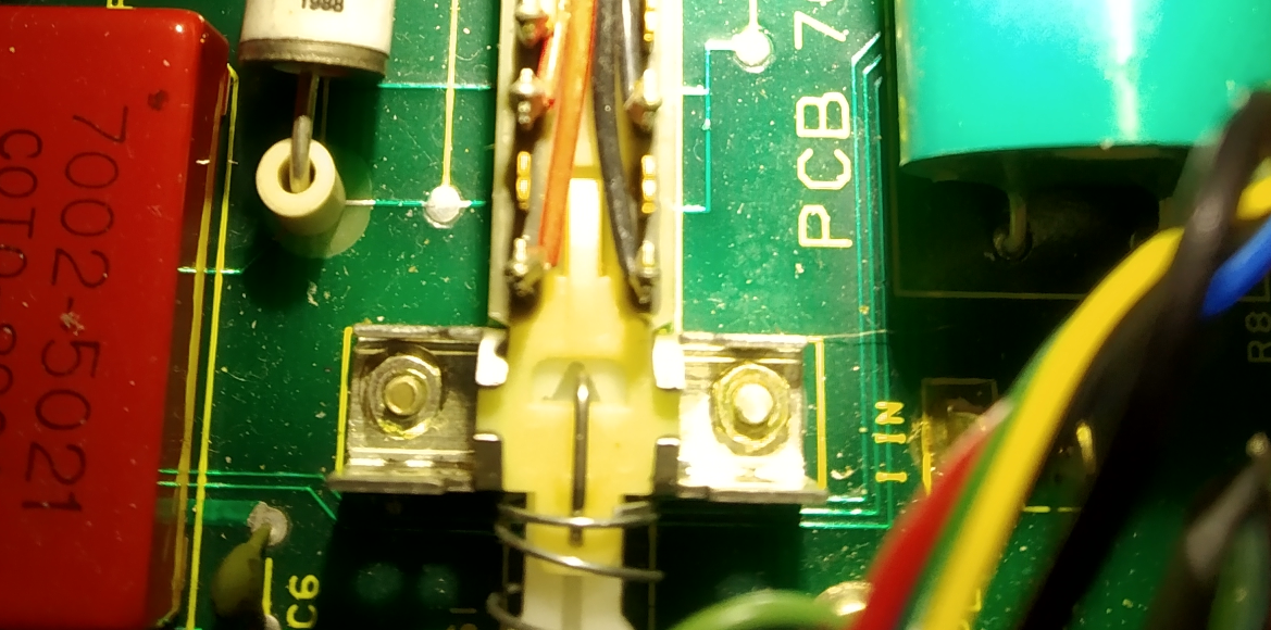
Meanwhile, I've just got my meter back together after swapping out all the power supply capacitors. Thankfully, what I thought was a plated through hole that I'd damaged, was just a plug of solder which had pulled out from the hole, but I couldn't see that properly until I actually got the capacitor out.  :phew:

I enlisted the help of my daughter to remove the rest of the capacitors so that I could use two soldering irons to melt the solder on both pins while she gave a gentle wobble and pull on the capacitor once I could see that the solder had melted. An extra pair of hands made the job so much easier!

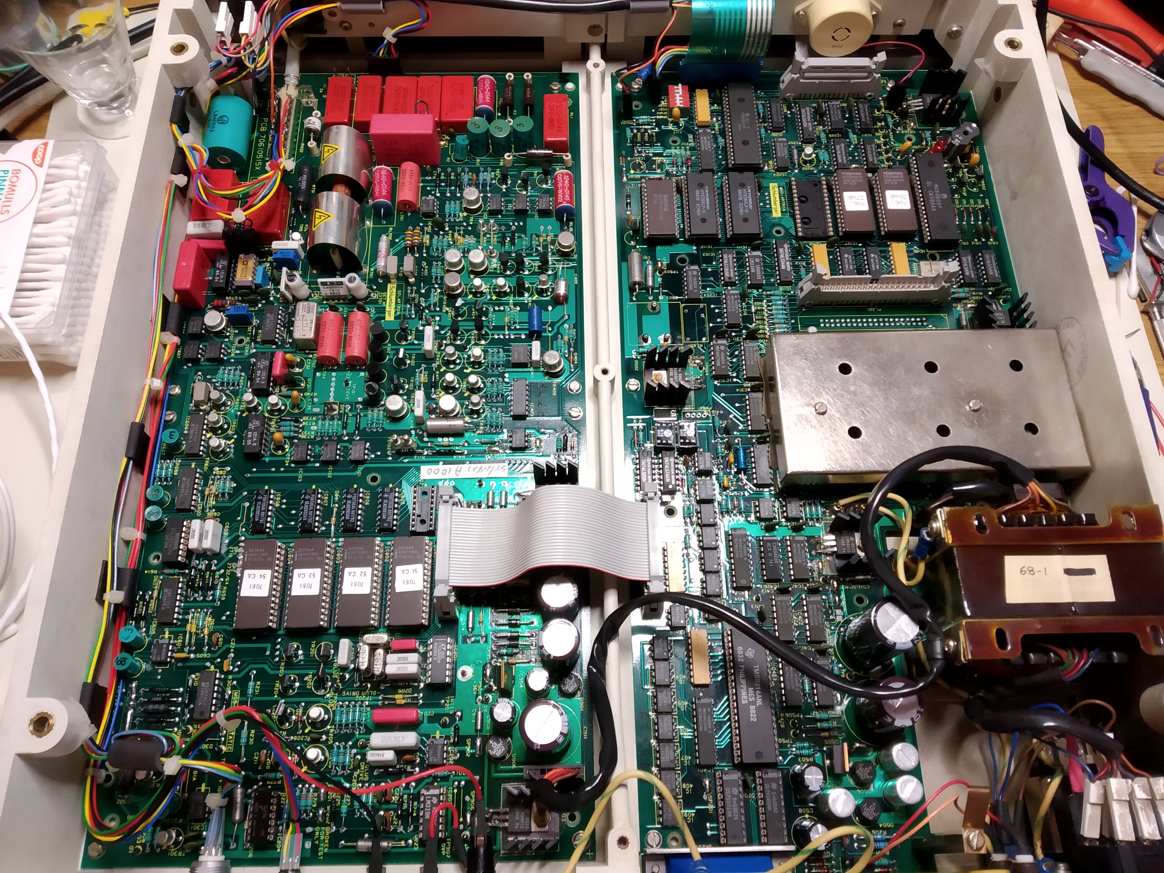
So my 7061 now has a full complement of Nichicon electrolytics, except for the three 47uF ones on the digital board. Two of those 47uF capacitors are not actually used for smoothing, instead, they couple the AC input of one bridge rectifier to the AC input of another bridge rectifier. (see below)


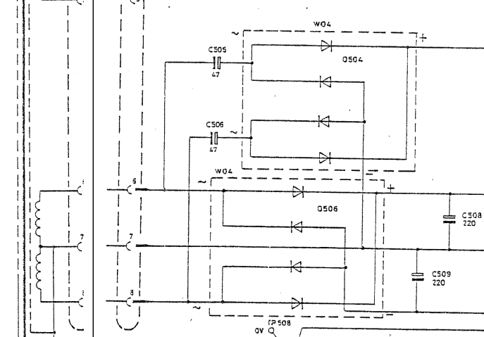
As these capacitors are not for smoothing, I bought the original Panasonic parts which are specified in the parts list. They have a much higher ESR than the ones which were fitted, but given the unusual use, I decided to trust the Solartron engineers on this one.

The rest of the electrolytics I used are all 105°C rated Nichicons. I took a higher temperature rating than the ones which were there knowing how hot it can get inside that case. The smoothing capacitors for the digital board are right next to the very hot transformer, so it seemed sensible to chose capacitors with a higher operating temperature.

The analogue board was really dirty when I looked at it close up...


This kind of dust and grime was everywhere on the top and bottom of the board - hardly something you want in a circuit where input impedances are in the gigaohms range!

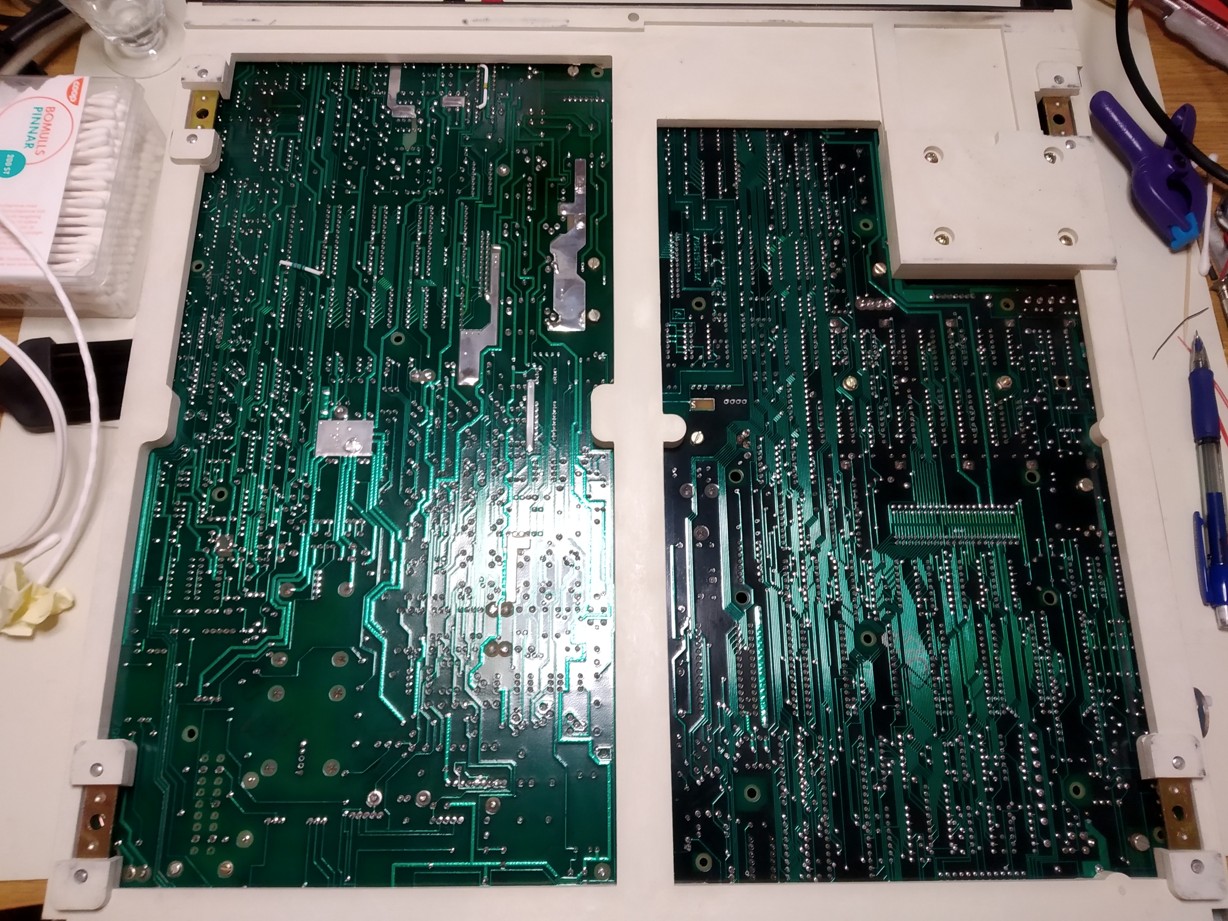
So, after replacing the capacitors, both boards were thoroughly cleaned with isopropyl alcohol a brush and cotton buds with particular focus on the analogue board. Both are now sparkling on both sides.


The meter is now fully cased again and warming up. I'll let it soak overnight and tomorrow I'll run some noise measurements and have a look at how well it reads very high resistances as well.
  Lord of Sealand
 

Offline grizewald

  • Frequent Contributor
  • **
  • Posts: 612
  • Country: ua
Re: Solartron7061
« Reply #178 on: May 10, 2020, 08:20:40 pm »
Using a small PTFE shorting block with the additiona centre pin added and shorted to all others,
it looks the same  :-BROKE
Which is a shame as I like an easy fix no matter how it's attained.
Time to give it a rest and have another go tomorrow.

Dek
(Attachment Link)

That's a shame. :(

I'm puzzled by your plot.

It says "range 10, 7 digits", but the numbers on the Y axis have only 5 digits after the decimal point when there should be 6.

So what am I actually seeing here? Does the Y axis go from -50μV to +40μV, implying you have 90μV of noise?
  Lord of Sealand
 

Offline DekTopic starter

  • Regular Contributor
  • *
  • Posts: 108
  • Country: gb
Re: Solartron7061
« Reply #179 on: May 10, 2020, 09:14:58 pm »
Yes,

The Y axis scale is +40uV to -50uV
Max was +27uV and Min -45uV

Log is about 15 minutes.
Same graph, but I've formatted the Y axis to show 6 digits.


Offline Kleinstein

  • Super Contributor
  • ***
  • Posts: 14195
  • Country: de
Re: Solartron7061
« Reply #180 on: May 10, 2020, 09:23:41 pm »
I had a look at the service manual and it looks like the chopper for the input amplifier is running at 50 Hz. So there is a chance that the source of the 50 Hz signal seen is the chopper amplifier and not mains. With the crystal clock installed there may be a chance to check this: both signals are a nominal 50 Hz, but not locked. So one could trigger the scope from one of the sources (mains or the crystal derived 50 Hz in the PLL part) and watch the 50 Hz hum seen (e.g. at the input of amplifier output). One should be able to see the difference in phase if the source a different.
 
The following users thanked this post: Dek

Offline grizewald

  • Frequent Contributor
  • **
  • Posts: 612
  • Country: ua
Re: Solartron7061
« Reply #181 on: May 11, 2020, 07:50:07 am »
Would be interesting to see what your instrument shows Grizewald, performing the same test  ;)


50Hz.
  Lord of Sealand
 

Offline grizewald

  • Frequent Contributor
  • **
  • Posts: 612
  • Country: ua
Re: Solartron7061
« Reply #182 on: May 11, 2020, 08:23:47 am »
And here's one hour of log with shorted inputs on the 10V range.


This makes no sense to me. It would appear to indicate that my last digit has about +/- 10 variation at 50 Hz, regardless of scale length.

The positive side of recapping and cleaning my meter is that the drift it exhibited previously seems to be gone. I'm also getting much better results reading a 100MΩ resistor.
« Last Edit: May 11, 2020, 09:01:02 am by grizewald »
  Lord of Sealand
 

Offline Kleinstein

  • Super Contributor
  • ***
  • Posts: 14195
  • Country: de
Re: Solartron7061
« Reply #183 on: May 11, 2020, 09:00:09 am »
In burst mode the chopper uses 1.5 kHz, so the 50 Hz can not come from the chopper. This may explain why more (some 5 mV versus some 0.2 mV) of the 50 Hz is seen, when in the slower modes.
Grizewald's meter seem to pic up less 50 Hz, but there still is some amplitude visible in burst mode.


For checking chopper artifacts acting back from the chopper to the input, fast mode with 1.5 kHz chopping may be better choice. So no more difficult separation of 50.x Hz mains and 50.y Hz from the clock. Chances are one would see (with the scope) some of the 1.5 kHz chopper frequency at the input and output of the amplifier. Some amplitude at the output is normal (depends on the exact amplifier design), but there should be very little at the input. The higher 50 Hz amplitude seen at 50 Hz may be a hint. I would consider the 5 mV amplitude rather high for the input side.
 

Offline grizewald

  • Frequent Contributor
  • **
  • Posts: 612
  • Country: ua
Re: Solartron7061
« Reply #184 on: May 11, 2020, 01:50:08 pm »
Just to make thinking a bit easier, I fixed the scan of the input amplifier.

  Lord of Sealand
 
The following users thanked this post: Kleinstein, DC1MC, Dek

Offline grizewald

  • Frequent Contributor
  • **
  • Posts: 612
  • Country: ua
Re: Solartron7061
« Reply #185 on: May 11, 2020, 03:56:59 pm »
Dek, when you took your burst mode measurement, were you using your crystal oscillator or the original PLL oscillator board?

The maintenance manual talks about the input amplifier switching needing to provide an equal number of readings in both positions to effectively remove any drift. The manuals hint at the crystal option having effects on the readings and refer back to chapter 1 of the user manual where they fail to describe these effects (just like they fail to describe the measurement cables).

I'm puzzling about what could introduce these 50Hz disturbances into the readings. The opto-isolators which are used extensively in the circuits are known to cause problems on Datron meters particularly when they start to age. Your meter is older than mine and we're both seeing very similar problems, but at different orders of magnitude. Just wondering if that might be a clue.
 
  Lord of Sealand
 

Offline Kleinstein

  • Super Contributor
  • ***
  • Posts: 14195
  • Country: de
Re: Solartron7061
« Reply #186 on: May 11, 2020, 05:27:32 pm »
The ADC and chopper use the same clock source, so there should be the same number of switching events, even if the frequency is far off.

The opto-couplers could in deed be a problem. One point that can change with ageing could be the delay times, causing some deviation from 50:50 ratio for the chopper. So a look at TP401, TP402 could help. Pin 1 of IC403 would be a similar signal, just less sensitive to loading. This should give a stable 50 / 1500 Hz signal with close to exact 50% on/off ratio.

Another possible problem could be a shift in the offset of TR412. This would cause more AC voltage  (50 / 1500 Hz) at the amplifiers output. If needed the JFET offset could be adjusted with R419/R420.

I would not expect something really broken in the main amplifier as the chopper amplifier at least to a large part still works.

Ripple of the +-36 V supply could also be a factor. The capacitor C412 (33 µF parallel to 5.6 V zener for current sources) could also cause trouble if the ESR goes to high.
 
The following users thanked this post: grizewald

Offline DekTopic starter

  • Regular Contributor
  • *
  • Posts: 108
  • Country: gb
Re: Solartron7061
« Reply #187 on: May 11, 2020, 05:58:59 pm »
Hi Grizewald,

Yes the burst was with the crystal oscillator fitted.
I also refereed back to chapter 1 to read up on the affects, but was met by tumble weed ;-)

The 50hz / 1.5khz switching looks OK, the square waves at TP401 402 look Ok too.
Checking the voltage at the +ve end of C412 I see a lot of switching noise (might just be my probe setup??)star cove as the ground reference (0Vp)
What is strange is the pks of the switching noise appear to be sinusoidal.
Can't see any noise that aligns with the 50hz or 1.5kh A B squarewaves.
Screen shot below.
Using my multimeter I get 5.8V across the cap / zenner
I get the same level of noise when looking at the test link point TL101 between the ip amp and integrator.


« Last Edit: May 11, 2020, 06:17:00 pm by Dek »
 

Offline DekTopic starter

  • Regular Contributor
  • *
  • Posts: 108
  • Country: gb
Re: Solartron7061
« Reply #188 on: May 11, 2020, 06:16:04 pm »
<edit>

Probe x was set wrong on my scope.
Noise on C412 is shown below, also the chopper signals which look OK.

I did pull out one end of C412 to check it albeit with my cheapo transistor cap ESR tester. It looked OK
Had a delivery today of a new 33uF tant I can compare and if necessary swap.
I'll look at the supply either side of R418


Checking the + and - 36v psu rails, both look like this.
Not so much ripple but switching noise?
Probe ground connected to TP205 0v.
About 30mV noise.


« Last Edit: May 11, 2020, 06:46:41 pm by Dek »
 

Offline Kleinstein

  • Super Contributor
  • ***
  • Posts: 14195
  • Country: de
Re: Solartron7061
« Reply #189 on: May 11, 2020, 06:51:36 pm »
Those noise spikes look odd, but somewhat expected for a circuit with lots of TTL type logic running relatively fast.

It is odd the spikes look so random, not really repeatable.
The test shown probably does not check R412, but more like the -36 V supply. Chances are both sides of C412 move the same.
Normally C400 and R418 should keep the spikes out.

Even for just the supply (other than maybe digital 5 V) there should no be such spikes. Also the amplifier output / bootstrap signal should not show this. The not so regular pattern for the spikes could point to the comparators / glug switching as a possible source.
 

Offline DekTopic starter

  • Regular Contributor
  • *
  • Posts: 108
  • Country: gb
Re: Solartron7061
« Reply #190 on: May 11, 2020, 08:26:10 pm »
Something very strange going on.

Touched the earth stud on the back of the meter with the scope probe - same sort of spiky noise.
Turned off the meter, same noise on the earth stud.
Touched the PC case, same noise.
Turned off the PC same
etc

I'll take the meter and scope into work tomorrow and see what happens there on a different supply.
Maybe flailing about in the dark but I'm now thinking possibly mains borne interference from powerline adaptors :-//
 

Offline Kleinstein

  • Super Contributor
  • ***
  • Posts: 14195
  • Country: de
Re: Solartron7061
« Reply #191 on: May 12, 2020, 05:43:15 am »
External noise / EMI could be a problem. There are plenty of switched mode supplies around, that could cause trouble. With much EMI around it can be difficult to measure with the scope. A good DMM would ideally have sufficient filtering.
 

Offline DekTopic starter

  • Regular Contributor
  • *
  • Posts: 108
  • Country: gb
Re: Solartron7061
« Reply #192 on: May 12, 2020, 04:35:49 pm »
Tested the 7061 at work and it exhibits the same drift and reading jumping as it does at home.
So that rules out mains interference.

Maybe now a good time to take out the analogue board and recap any that I didn't replace previously, which will be everything that is not part of the PSU.

Dek
 

Offline DekTopic starter

  • Regular Contributor
  • *
  • Posts: 108
  • Country: gb
Re: Solartron7061
« Reply #193 on: May 13, 2020, 06:39:02 am »
Changed the 5 remaining Tants on the analogue board, gave it a good clean, appears to be no change :-(
Need to do a log and graph, but certainly the second from last digit still jumping.

"Jumping" is not quite the correct word as the error appears to be cyclic over a period of approx 5 to 10 seconds with a noticeable big jump occasionally.

More probing and head scratching required.
 

Offline grizewald

  • Frequent Contributor
  • **
  • Posts: 612
  • Country: ua
Re: Solartron7061
« Reply #194 on: May 13, 2020, 09:24:17 am »
That's exactly the same pattern as I see, just an order of magnitude less.
  Lord of Sealand
 

Offline DekTopic starter

  • Regular Contributor
  • *
  • Posts: 108
  • Country: gb
Re: Solartron7061
« Reply #195 on: May 16, 2020, 04:21:32 pm »
Some progress:-

Took out the link TL101
With Fluke multimeter  from 0v to TR3 and see the previously measured 7 to 10mv AC
7061 meter set on the 0.1v range and IP socket shorted (excluding pin 5 guard)
The 7061 display fluctuates about ~2 counts of the last 7 digit (approx 0.000,000.5)
Temporarily re-connect TL101 and the display fluctuates 2 or 3 counts of the 5th digit.  (approx 0.000,035.1)


Thinking back to this where removing the test link eliminated the noise and fluctuation, gave me an idea to help with escaping from this rabbit hole :-)
To prove that the AD converter is working properly and the glugs are stable, I can inject say 1vdc  onto the downstream test link pin.
This will feed 1vdc directly into the intergrator. If I get a stable reading then the problem is definitely with the IP ranging or IP amplifier, or opto isolators. The absolute voltage does not matter as I'm looking for just a stable reading.
At least it will reduce the search area.

Grize' and Klein' what do you think?

Dek.


Offline Kleinstein

  • Super Contributor
  • ***
  • Posts: 14195
  • Country: de
Re: Solartron7061
« Reply #196 on: May 16, 2020, 04:58:45 pm »
Feeding a signal directly to the ADC (e.g. bypassing the input amplifier) is possible. The obvious choice for a first test would be 0 V.
 

Offline grizewald

  • Frequent Contributor
  • **
  • Posts: 612
  • Country: ua
Re: Solartron7061
« Reply #197 on: May 17, 2020, 09:47:24 pm »

To prove that the AD converter is working properly and the glugs are stable, I can inject say 1vdc  onto the downstream test link pin.
This will feed 1vdc directly into the intergrator. If I get a stable reading then the problem is definitely with the IP ranging or IP amplifier, or opto isolators. The absolute voltage does not matter as I'm looking for just a stable reading.
At least it will reduce the search area.

Grize' and Klein' what do you think?

Dek.


It has to be worth a try!
  Lord of Sealand


Share me

Digg  Facebook  SlashDot  Delicious  Technorati  Twitter  Google  Yahoo
Smf