Author Topic: Solartron7061  (Read 20964 times)

0 Members and 1 Guest are viewing this topic.

Offline DekTopic starter

  • Regular Contributor
  • *
  • Posts: 108
  • Country: gb
Re: Solartron7061
« Reply #100 on: April 05, 2020, 02:53:53 pm »
Well, that was effective as trying to solder titanium to a lump of coal :-DD
No change in the  meter behaviour.
Meter still shows OVERLOAD when selecting 4 digits and G.Death on startup.

IC310 is badly corroded as is  IC312.
I think there is only one thing for it and that is to exchange IC310. (Might do IC312 while I'm at it).


Checked again
pin 11 low
pin 12  low
pin 13 1.5khz pulses
pin 14  1.5khz pulses (wasn't expecting QA and QB to be identical)
For a moment I thought that I could connect say QB to the cut leg of pin 11, but the timing is wrong.


Dek.


Offline grizewald

  • Frequent Contributor
  • **
  • Posts: 612
  • Country: ua
Re: Solartron7061
« Reply #101 on: April 05, 2020, 10:32:44 pm »
The alkali that leaks from the battery when it gets too old is really nasty stuff. It is normally potassium hydroxide or sodium hydroxide. It has obviously leaked out further than the first pictures you posted would suggest.

If you don't remove every trace of the leak and neutralise the alkali, then it will continue to damage both the components and the PCB, eating away at the vias, particularly if they are under an IC and the alkali has seeped in between the bottom of the IC and the PCB.

The best way to stop this getting any worse is to thoroughly wash down the PCB over the complete area affected by the leak several times with a dilute solution of spirit vinegar and a brush. Then with multiple washes of distilled water (if you live in a soft water area, tap water is OK) followed by a final couple of washes with pure isopropanol. If you can see places where the alkali may have got in under the ICs, make sure that you can run the cleaning solutions underneath them. Use an air jet to make sure that the cleaning agent gets blown out from under any ICs after each wash. If there are vias under the ICs, you will need to remove the ICs to properly deal with the vias.

From your picture, I can see that the solder in many of the vias has turned grey and dull. This is from the battery leak and it would be wise to test each via to make sure it still works, desolder any grey vias, neutralise any remaining alkali  and then fill them with fresh solder. If you don't, you may find them going open circuit as the alkali can get down into them and continue eating away at the through hole plating from the inside. You will also discover that it is really difficult to remove the grey solder as it doesn't want to melt properly any more. I had to resort to a very thin stainless steel needle to completely clear some of them and then install a thin wire through the via and scrape back a little solder resist on each side to solder the wire to the tracks that the via connected.

If the PCB has internal layers, it is often a case of "beyond economic repair" when they get hit by a battery leak as repairing vias that connect to internal layers is very difficult and time consuming.
 
Leaking batteries are a real menace on test gear of this era. I'm still working on fixing a Solartron 7151 I bought which had been subject to a catastrophic battery leak. I saved some pictures of the horror and what I've had to do so far to repair the damage.

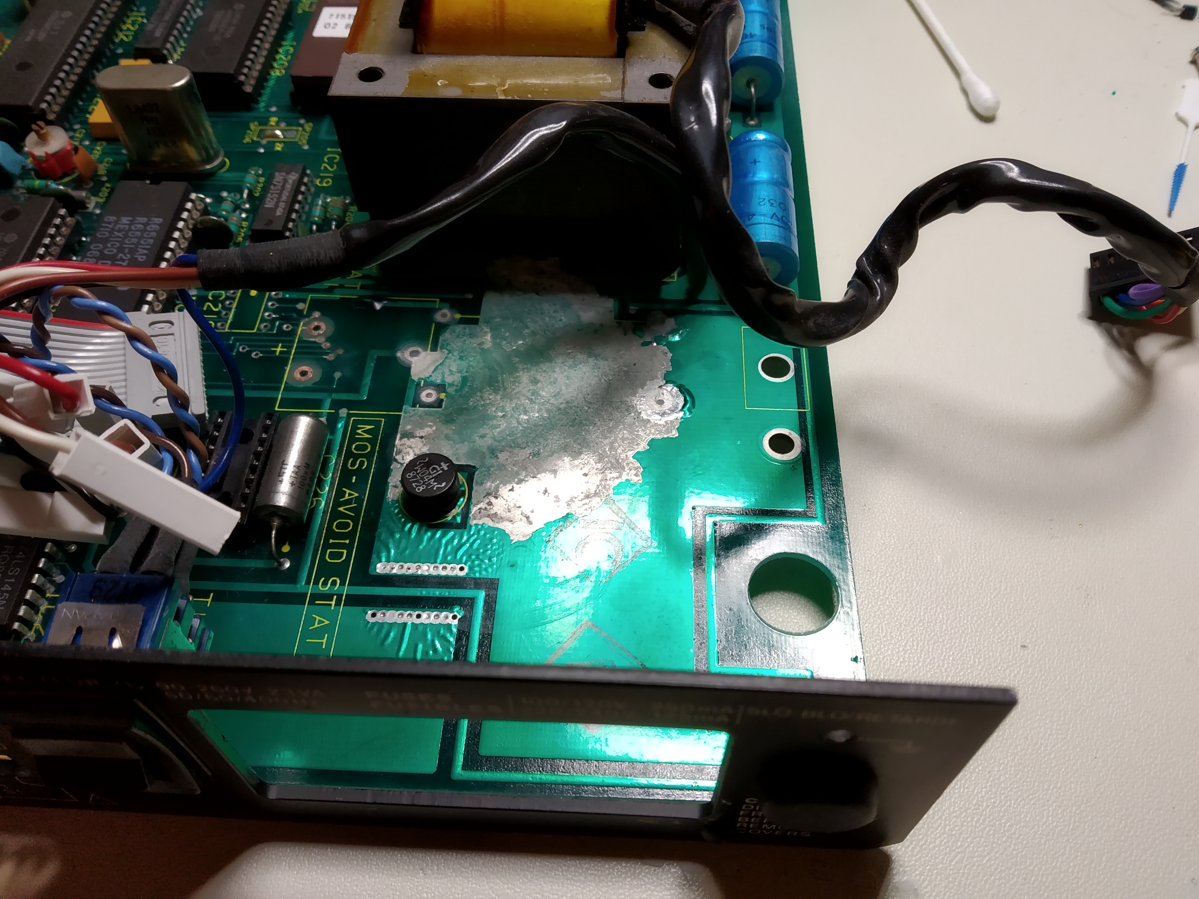
At first, it didn't look too bad once I'd removed the leaking battery:


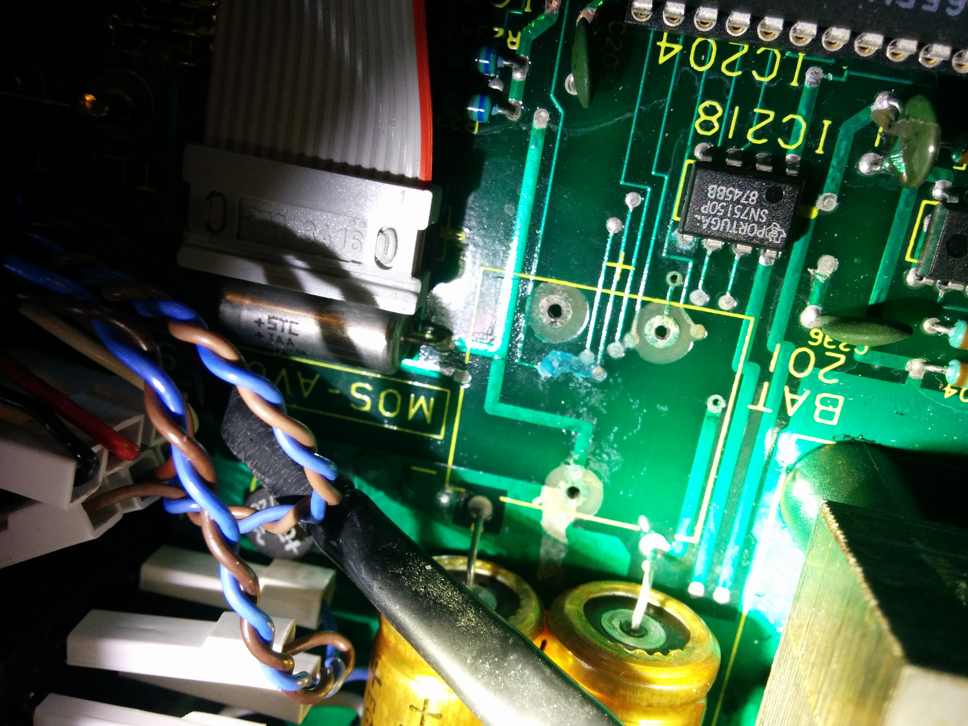
But the more I looked, the worse it got. Just about every via here is open circuit and the 75150 chip in the first picture is dead.


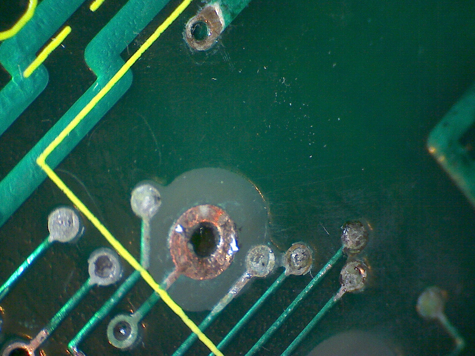
Then I discovered that the alkali can actually wick under the layer of solder resist and spread even further than you think it has. As soon as I poked at the solder resist, it would simply flake off, so I had to start stripping that back until I got to the point where it was no longer flaky, scrape off a little more to be sure and then clean everything again starting with the vinegar solution.


The pictures are all clickable for full resolution.

If you can see that IC310 and 312 are badly corroded, then the best thing to do is remove them, clean again, repair any open vias and install replacements. It's always better to err on the side of caution and limit any further damage as much as you can. I'll keep my fingers crossed that the damage doesn't extend too far!

Hopefully, all this hard work will give you a perfectly working reward.
 
  Lord of Sealand
 

Offline DekTopic starter

  • Regular Contributor
  • *
  • Posts: 108
  • Country: gb
Re: Solartron7061
« Reply #102 on: April 06, 2020, 06:27:24 pm »
Hi Grize,

Wow that's some repair project.

I've extracted IC310, the tracks and pads look OK some surface corrosion.
GND and VCC pads are connected to internal ground planes which makes it difficult to remove the cut legs using minimum heat.
I doubt 'thermals' weren't invented in the 80s !

Now reading your post above I will certainly rework the vias under IC310 before fitting.
For now I will re-solder IC310, (delivery expected tomorrow) hopefully this will resolve the G.Death issue, then look at repairing the remaining corrosion after.

Popped a few holes in the clock circuitry enclosure lid. (I thought this was stainless steel but actually it's folded from copper sheet).... and now looks like a bought one  :-DD

Dek.


<edit>
Managed to work a few of the vias - the soldering iron and hot air nozzle combination works well.


and the full horror of the battery leakage on the nearby components.


Extent of corrosion
964704-4
« Last Edit: April 06, 2020, 07:31:27 pm by Dek »
 

Offline grizewald

  • Frequent Contributor
  • **
  • Posts: 612
  • Country: ua
Re: Solartron7061
« Reply #103 on: April 07, 2020, 06:59:47 am »
Nice job!   :-+

I'll have to give your trick with blowing the solder out with hot air a try on my next repair. It certainly avoids cooling the solder down just when you need it to stay liquid.
  Lord of Sealand
 

Offline DekTopic starter

  • Regular Contributor
  • *
  • Posts: 108
  • Country: gb
Re: Solartron7061
« Reply #104 on: April 07, 2020, 09:21:59 am »
Strictly not my trick.
I was watching some guy on You tube extract ICs whole, would heat the IC legs in the normal way, pull out the IC and while the board was still hot, blow out the holes. I'm cutting the IC legs and extracting individually, then once the legs are removed go round with the iron and hot air to clear out the holes.
The only issue is that the tip of the nozzle can scratch off some of the solder resist. The solder resist on my 7061 PCB seems particularly fragile in that respect.
I've since polished the end of the nozzle smooth to see if this helps and use thin strips of capton tape in an attempt to protect the solder resist.
The other thing to watch is keeping the soldering iron with minimum solder, the hot air 'jet' can blow blobs of solder about so I also put capton tape to stop small solder spheres from disappearing under nearby ICs ! 

The replacement 74HC161s have arrived ...will it be   :-+ or  :-BROKE
"Tune in later to find out"  :-DD

Dek.
« Last Edit: April 07, 2020, 09:24:05 am by Dek »
 

Offline DekTopic starter

  • Regular Contributor
  • *
  • Posts: 108
  • Country: gb
Re: Solartron7061
« Reply #105 on: April 07, 2020, 06:45:58 pm »
Success

Soldered the new lucky IC , prayed to the magic smoke gods and turned on.
SELF TEST PASS
7061 INITIALISED.
Super-bloody-duper  8)
4 digits mode now doesn't flash up OVERLOAD but measures correctly.

A quick look Ohms and dcV working.
Obviously lots more to do in checking all the ranges etc, but it appears that the meter is now working.
I have the parts to build a Arduino GPIB interface which will help with further checks and tests once the new GPIB controller arrives.

Thank you Grizwald and Kleinstein for your help, very very much appreciated  :clap: :-+ :clap: :-+


The following users thanked this post: Nuno_pt, grizewald

Offline Nuno_pt

  • Frequent Contributor
  • **
  • Posts: 435
  • Country: pt
Re: Solartron7061
« Reply #106 on: April 07, 2020, 06:54:07 pm »
Nice work Dek, glad you got it going.
Nuno
CT2IRY
 
The following users thanked this post: Dek

Offline grizewald

  • Frequent Contributor
  • **
  • Posts: 612
  • Country: ua
Re: Solartron7061
« Reply #107 on: April 07, 2020, 06:55:17 pm »
That's great news Dek! Congratulations!

  Lord of Sealand
 
The following users thanked this post: Dek

Offline coromonadalix

  • Super Contributor
  • ***
  • Posts: 5895
  • Country: ca
Re: Solartron7061
« Reply #108 on: April 08, 2020, 10:27:44 am »
 :-+  another "oldie" saved
 
The following users thanked this post: Dek

Offline DekTopic starter

  • Regular Contributor
  • *
  • Posts: 108
  • Country: gb
Re: Solartron7061
« Reply #109 on: April 09, 2020, 05:26:36 pm »
Now on with a bit of maintenance.
I've ordered some UV curable solder resist to tidy up the area around the battery. I'll take out the battery and other components to give this area a good clean and re-coat of resist.
While at it I'll clean out the holes of the spare IC and refill with solder etc.

Something strange going on with the mains filter, if its a filter at all! No sign of earlier eruption / fire / explosion though.
It's been got at in it's previous life, botch job on the soldering and installed upside down.
New filter on the way and I'll be a lot more comfortable once it's fitted with the new filter.

Arduino GPIB interface under construction - it will be interesting to see the meter noise and compare this to Grizewalds 7061
I'm a bit suspicious as with the inputs shorted it does look noisy - maybe more fault finding fun to come ! :-DD


Offline grizewald

  • Frequent Contributor
  • **
  • Posts: 612
  • Country: ua
Re: Solartron7061
« Reply #110 on: April 10, 2020, 12:40:37 pm »
Good idea on using some UV solder mask to replace what's missing. I did that also on my 7151, although I found it impossible to buy locally as it's classed as 'dangerous' here in Sweden and can only be sold to companies. Thank goodness for eBay!

Your mains input selector/filter/fuse holder is very much missing the filter part! (It's the silver box at the bottom of the unit in my photo here.)


Whoever bodged yours deserves a good slapping for leaving those mains carrying leads with no heat shrink just waiting to be accidentally touched while the case is open and you are working on the meter.  :palm:

Good to hear you have already located a replacement. Hopefully it's not a "New Old Stock" as the filter is primed to burst into flames by age, not use. Mouser have brand new units in stock otherwise (Mouser part number 631-FN372-2-21)

Once you have all your remedial work finished and if the meter is still as noisy as mine, it would tend to confirm that the noise I'm seeing is typical for this particular design. Certainly, Klienstein thought that this may well be the case for these meters and I know from the work that Mickle T. detailed when trying to solve noise problems on the 7081 (which has a very similar ADC design to the 7061, that it's hard to achieve large improvements. So far, I can certainly agree that using an LTC1052 instead of the original ICL7650 chopper amp gives around a 30% improvement. My gut feeling is that every further 10% improvement from there is likely to be exponentially harder to achieve.

Still, there are quite a few things I have not tried yet, partly because I don't want to risk ruining the calibration and adjustment that I have had done to my meter. A noisy but accurate meter is better than a quiet meter which is inaccurate to an unknown degree!


  Lord of Sealand
 

Offline tggzzz

  • Super Contributor
  • ***
  • Posts: 19493
  • Country: gb
  • Numbers, not adjectives
    • Having fun doing more, with less
Re: Solartron7061
« Reply #111 on: April 10, 2020, 03:42:55 pm »
Once you have all your remedial work finished and if the meter is still as noisy as mine, it would tend to confirm that the noise I'm seeing is typical for this particular design. Certainly, Klienstein thought that this may well be the case for these meters and I know from the work that Mickle T. detailed when trying to solve noise problems on the 7081 (which has a very similar ADC design to the 7061, that it's hard to achieve large improvements. So far, I can certainly agree that using an LTC1052 instead of the original ICL7650 chopper amp gives around a 30% improvement. My gut feeling is that every further 10% improvement from there is likely to be exponentially harder to achieve.

If you can, find a saturated Weston standard cell (or perhaps other types of cell) and use that as a "noiseless" input signal. Variations in the output are then due to the DVM, or temperature shift, or bad measurement practice.

This is my 7081 measuring such a cell over a day; the vertical axis is 10µV/10ppm and 1µV/1ppm. The temperature variation was ~1C, and you can see a ~40µV change in the voltage. That dwarfs the noise, which is <1µV.

I don't know what the three impulses are, but they aren't popcorn noise. I've seen popcorn noise 15V/1.5ppm, on an old zener reference.
« Last Edit: April 10, 2020, 03:45:37 pm by tggzzz »
There are lies, damned lies, statistics - and ADC/DAC specs.
Glider pilot's aphorism: "there is no substitute for span". Retort: "There is a substitute: skill+imagination. But you can buy span".
Having fun doing more, with less
 

Offline Kleinstein

  • Super Contributor
  • ***
  • Posts: 14192
  • Country: de
Re: Solartron7061
« Reply #112 on: April 10, 2020, 04:12:54 pm »
With Weston cells there is always some danger that they may not be absolute stable because they where moved the last few days. The saturated cells also have quite some TC, so they need a really stable temperature. Still it should not be 40 ppm/K.
With a high impedance source, input current can be an issue too. There can also be variations in gain, especially if using the 1 V range. The Solartron meters use a well trimmed zener current and with the 7081 they use a relatively odd construction with opto-coupler and a DAC to set the current. These opto-couplers can fail, running the zener with a wrong current and thus much higher than intended TC. So chances are there is something wrong with the 7081 or maybe the weston cell.
For just the scale factor one could try measuring the internal zener reference - this would reduce the possible error sources.

Anyway testing the pure ADC noise (near zero) and scale factor variations are 2 different things both have there justification.
Usually the noise near zero is the first step as it is easier.

If changing from the ICL7650 to an LTC1052 allready did improve the noise quite a bit, this indicates that the OP was a significant source and the meter may not be far away from the intended performance. These old Solartrons are relatively noisy by today's standard even if they claim high resolution. By design the resolution is limited, as they only use a single reference level. So even if one can reduce the additional noise there will likely be a limit from quantization noise, at least for the not so very slow speeds.
 

Offline tggzzz

  • Super Contributor
  • ***
  • Posts: 19493
  • Country: gb
  • Numbers, not adjectives
    • Having fun doing more, with less
Re: Solartron7061
« Reply #113 on: April 10, 2020, 05:34:23 pm »
With Weston cells there is always some danger that they may not be absolute stable because they where moved the last few days. The saturated cells also have quite some TC, so they need a really stable temperature. Still it should not be 40 ppm/K.

For saturated cells the tempco is about 40µV/K, so roughly 40ppm. From a Muirhead Journal article on Weston cells, second column line 6...

« Last Edit: April 10, 2020, 05:36:48 pm by tggzzz »
There are lies, damned lies, statistics - and ADC/DAC specs.
Glider pilot's aphorism: "there is no substitute for span". Retort: "There is a substitute: skill+imagination. But you can buy span".
Having fun doing more, with less
 

Offline DekTopic starter

  • Regular Contributor
  • *
  • Posts: 108
  • Country: gb
Re: Solartron7061
« Reply #114 on: April 10, 2020, 10:18:55 pm »
I ran a few programs today - each over 1 hour, no filter, range 10
Meter warmed for 3 to 4 hrs
Typically looks bad as
Max 6.341934-5
Min -5.531311-5
Mean -3.559899-6
SD 1.638492-5
Var 2.684659-10
Rms 1.676719-5

Just watching the display over approx 2 minutes
Range 1 range i.e 0.000,000.0 last two digits vary 0.000,012.3 to approx 0.000,002.4
Range 10 i.e 0.000,000 last two digits fluctuate -0.000,044 to -0.000,013
Range 100  0.000.00  last two digits fluctuate 0.001,19 to 0.000,54
Range 1000 0.000.0 last two digits fluctuate 0.003,1 to -0.000,1

Now trying to understand whats happening :-// Maybe I need to take a closer look at the floating PSU now the Glug Death is fixed.


Offline Kleinstein

  • Super Contributor
  • ***
  • Posts: 14192
  • Country: de
Re: Solartron7061
« Reply #115 on: April 11, 2020, 08:10:43 am »
Some 16 µV RMS noise is not that far off what grizewald measured for his meter. So this level may be kind of normal.
Changes to the mains grid could contribute to less accurate operation of the PLL. The operation with a fixed crystal clock would give a hint.
 

Offline grizewald

  • Frequent Contributor
  • **
  • Posts: 612
  • Country: ua
Re: Solartron7061
« Reply #116 on: April 11, 2020, 11:00:19 am »
I think I was seeing more like 12μV p-p, but let me repeat exactly the same test as you have made Dek.

I just turned the meter on, so I'll let it warm up properly and then run the STATS
program for 10V range, shorted inputs, no filter for 30 minutes or so and then we'll
have two similar apples to compare.

  Lord of Sealand
 

Offline grizewald

  • Frequent Contributor
  • **
  • Posts: 612
  • Country: ua
Re: Solartron7061
« Reply #117 on: April 11, 2020, 04:34:06 pm »
Time for some results!

My results are from 1836 samples in 7 digit mode, so just a shade over 1 hour.

Code: [Select]
Dek          grizewald
Max     6.341934E-05     4.768371E-06
Min    -5.531311E-05    -1.049041E-05
P-P                      1.525878E-05
Mean   -3.559899E-06    -2.975560E-06
SD      1.638492E-05     2.836091E-06
Var     2.684659E-10     8.043415E-12
RMS 1.676719E-05     4.110641E-06

My 7061 has the original ICL7650 installed. Just for fun, I'll quickly power down the meter and swap it for the LTC1052
and run another hour once the meter has re-stabilised (which shouldn't take that long as it's nice and hot now.)

It certainly looks as if Dek's meter has some additional noise compared to mine.

Did you sort out all the various noisy power rails that you reported in your initial rail check Dek?

For reference, here's what I found when I checked all my power rails:


7061 Rail Check

  Digital Board
TestPoint   0VRef         Spec               Actual / Ripple
501           508    +5V +/- 0.25V            5.09V / < 0.01V
502           508    +5V +/- 0.25V            5.07V / < 0.01V
503           508    +4.5V +/- 0.5V       3.96V (off) 4.50V (on)
504           508    +5V +/- 0.25V            5.07V / < 0.01V
505           508    +41V +/- 2V               41.7V / < 0.01V
506           508    +32V +/- 5V               32.5V / 0.12V
507           508    -32V +/- 5V               -32.7V / 0.02V
509           508    +5V +/- 0.25V            5.08V / < 0.01V

  Analogue Board
TestPoint   0VRef         Spec               Actual / Ripple
901           903    +36V +/- 2V              36.1V / < 0.01V
902           903    +15V +/- 1V              15.4V / < 0.01V
904           903    -15V +/- 1V              -15.2V / < 0.01V
905           903    +36V +/- 2V             -35.8V / < 0.01V
906           903    +5V +/- 0.25V            4.98V / < 0.01V

  Reference Voltage
302           303         -10V                   -10.024V / < 0.01V
301           303         +10V                   10.024V / < 0.01V


« Last Edit: April 11, 2020, 05:05:47 pm by grizewald »
  Lord of Sealand
 

Offline DekTopic starter

  • Regular Contributor
  • *
  • Posts: 108
  • Country: gb
Re: Solartron7061
« Reply #118 on: April 11, 2020, 05:34:23 pm »
Hi Grizewald,

Thanks for that.
I'm running another prog for an hour to get another set of results, but looking at your last run, my meter is much noisier.
I haven't looked at the power supply since my first check, so it likely the rails still have significant ripple.

I'll check as soon as the current prog runs for over the hour.
To ensure comparable results, did you check with DMM or oscilloscope?

Dek.
 

Offline grizewald

  • Frequent Contributor
  • **
  • Posts: 612
  • Country: ua
Re: Solartron7061
« Reply #119 on: April 11, 2020, 06:16:16 pm »
I checked with my Brymen 867S in DC+AC mode. The AC part always starts off at an alarming value, but if you wait a while, it slowly comes down to the actual value.

Getting a scope to give an accurate reading of ripple is next to impossible unless you can keep the ground lead to just a few millimetres and that's pretty much impossible in this case.

I'll post the results from the LTC1052 in a bit.
  Lord of Sealand
 

Offline grizewald

  • Frequent Contributor
  • **
  • Posts: 612
  • Country: ua
Re: Solartron7061
« Reply #120 on: April 11, 2020, 06:44:47 pm »
Updated with results from the LTC1052 based on 1841 readings for comparison.

Code: [Select]
Dek          grizewald       griz/LTC1052
Max     6.341934E-05     4.768371E-06     1.001358E-05
Min    -5.531311E-05    -1.049041E-05    -4.291534E-06
P-P                      1.525878E-05     1.430511E-05
Mean   -3.559899E-06    -2.975560E-06     3.347188E-06
SD      1.638492E-05     2.836091E-06     2.600971E-06
Var     2.684659E-10     8.043415E-12     6.765054E-12
RMS 1.676719E-05     4.110641E-06     4.238953E-06

It's a slight improvement. The only reason I don't leave it in the meter is that when I put the LTC1052 in the hot meter and the LTC1052 comes up to operating temperature, I'm left with a 355μV offset from 0V. When the first auto-zero comes around after 15 minutes, the meter zeros out the offset, but I'm not confident that this isn't going to influence the meter's calibration, particularly from the point of view of linearity over the range. So, until I get get a larger set of voltage reference artefacts ready to compare them between the OP amp it was calibrated with and the LTC1052, I'm holding back from making it a permanent change.
  Lord of Sealand
 

Offline Kleinstein

  • Super Contributor
  • ***
  • Posts: 14192
  • Country: de
Re: Solartron7061
« Reply #121 on: April 11, 2020, 07:26:46 pm »
The step from 2.83 µV to 2.6 µV noise does not look large, but when doing the difference of squares it is quite a bit. I would not have expected that much noise from the ICL7650.

The SD reading may sill include some drift part, if not absolutely stable temperature, or history before the data.set was started.


The observed offset of 355 µV is really large. Both the ICL7650 and LTZ1052 are normally low offset (e.g. a few µV) and also the bias should not be so large. There is a gain of 5 for the OPs offset, but it should still not be that high.
A factor effecting this could be the odd lack of decoupling at the AZ OP - normally a no-go.

If I remember right from an old thread about the 7081, there was quite some noise from the comparator reading: so of the type that one reading is to high and the following reading to low. If one has a long enough data set, one could look at the Allan deviation plot to see if the noise is more white, with 1/f type or with anti-correlation between adjacent points.
 
The following users thanked this post: grizewald

Offline DekTopic starter

  • Regular Contributor
  • *
  • Posts: 108
  • Country: gb
Re: Solartron7061
« Reply #122 on: April 11, 2020, 07:29:10 pm »

Code: [Select]
    Dek             grizewald                          Dek
Max     6.341934E-05     4.768371E-06   9.775101E-5
Min    -5.531311E-05    -1.049041E-05    -8.249282E-5
P-P                      1.525878E-05
Mean   -3.559899E-06    -2.975560E-06    -4.682388E-6
SD      1.638492E-05     2.836091E-06        2.665109E-5
Var     2.684659E-10     8.043415E-12        7.102809E-10
RMS    1.676719E-05     4.110641E-06        2.705930E-5


7061 Rail Check

  Digital Board
TestPoint   0VRef         Spec               Actual / Ripple                             Dek
501           508    +5V +/- 0.25V            5.09V / < 0.01V                4.90V/ <0.01V
502           508    +5V +/- 0.25V            5.07V / < 0.01V                4.99V/ <0.01V
503           508    +4.5V +/- 0.5V       3.96V (off) 4.50V (on)           2.02V and falling (off) 4.90V (on)
504           508    +5V +/- 0.25V            5.07V / < 0.01V                5.05V/ 2mV
505           508    +41V +/- 2V               41.7V / < 0.01V                40.82/  8mV
506           508    +32V +/- 5V               32.5V / 0.12V                   29.0/ 0.15v   
507           508    -32V +/- 5V               -32.7V / 0.02V                    -29.2V/ 9mV
509           508    +5V +/- 0.25V            5.08V / < 0.01V                5.06V/ 5mV

  Analogue Board
TestPoint   0VRef         Spec               Actual / Ripple
901           903    +36V +/- 2V              36.1V / < 0.01V                  35.6V/    1mV
902           903    +15V +/- 1V              15.4V / < 0.01V                  14.98V/ 0.5mV
904           903    -15V +/- 1V              -15.2V / < 0.01V                  -14.96V/ 0.5mV
905           903    +36V +/- 2V             -35.8V / < 0.01V                  -35.4V/ 0.8mV
906           903    +5V +/- 0.25V            4.98V / < 0.01V                  5.10V/ 0.7mV
 
  Reference Voltage                                                                                   
302           303         -10V                   -10.024V / < 0.01V                -10.03V / 4mV
301           303         +10V                   10.024V / < 0.01V                10.02V/ 2mV 

So the +32V rail looks like it needs some attention.
As a simple comparison looking at the + and - 32V rails on the scope, +32V has 50mV ripple and the -32V rail 5mV
Not sure whats going on the the RAM back up battery- D502 could be duff, so this also needs looking at.

Along with the new filter I've on order from Mouser,  also a LTC1052 .

<edit> D502 was toast, the poor battery was back feeding the 5v rail..... temporarily soldered in a 1N4148 and things look like they should be.
« Last Edit: April 11, 2020, 08:00:17 pm by Dek »
 

Offline grizewald

  • Frequent Contributor
  • **
  • Posts: 612
  • Country: ua
Re: Solartron7061
« Reply #123 on: April 11, 2020, 08:27:48 pm »
The step from 2.83 µV to 2.6 µV noise does not look large, but when doing the difference of squares it is quite a bit. I would not have expected that much noise from the ICL7650.

The SD reading may sill include some drift part, if not absolutely stable temperature, or history before the data.set was started.

The drift of the meter has always troubled me. If you remember on my 7061 noise thread, I posted this plot:


Here, I've turned off the regular 15 minute drift correction. The trend, over an eight hour period, is always downward and seems too large to be only caused by the very small drop in room temperature over the eight hours.

I understand why the meter would need to perform a drift correct periodically, but I don't see why that drift should always be in a negative direction.

Neither do I understand why the drift corrections would be as large as they are in this 24 hour plot of a Weston cell with drift correction on.


The contrast to the plot which tggzzz posted earlier is striking.

I'm wondering if there's some kind of leakage at play here. I have not had the analogue board out of the meter, so I'm thinking that maybe I should give the whole analogue board a good clean and several washes with iso just to rule out any surface contamination causing these effects. Even if this is part of the problem, I don't understand why there would be a seemingly constant negative drift over many hours; surely it has to level out at some point?

The observed offset of 355 µV is really large. Both the ICL7650 and LTZ1052 are normally low offset (e.g. a few µV) and also the bias should not be so large. There is a gain of 5 for the OPs offset, but it should still not be that high.
A factor effecting this could be the odd lack of decoupling at the AZ OP - normally a no-go.

Well, the meter was calibrated with the original ICL7650, which includes setting the zero point, so that may imply that the original ICL7650 has a large negative offset due to a problem with the OP amp itself and that switching to the LTC1052 shows how much of a negative offset the calibration is actually masking.

The only range which actually failed calibration was the current range. The zero reading for current (even after calibration) shows 0.0261mA. I noticed that this offset appears on the second reading shown after enabling the current range. This would imply some kind of leakage which occurs after the shunt resistor is switched into the measurement path for the first time. A faulty relay perhaps or some kind of leakage around that part of the PCB?

If I remember right from an old thread about the 7081, there was quite some noise from the comparator reading: so of the type that one reading is to high and the following reading to low. If one has a long enough data set, one could look at the Allan deviation plot to see if the noise is more white, with 1/f type or with anti-correlation between adjacent points.

I can easily collect measurement data of any reasonable length. Could you suggest how much data would be needed and how I'd go about processing it to create such a plot?

In the mean time, I should probably collect a 24 hour log with inputs shorted on the 10V range and drift correction off with the new LTC1052 installed to see if the overall drift tendency is any different with the new OP amp.
« Last Edit: April 12, 2020, 04:32:11 pm by grizewald »
  Lord of Sealand
 

Offline grizewald

  • Frequent Contributor
  • **
  • Posts: 612
  • Country: ua
Re: Solartron7061
« Reply #124 on: April 11, 2020, 08:32:18 pm »

So the +32V rail looks like it needs some attention.
As a simple comparison looking at the + and - 32V rails on the scope, +32V has 50mV ripple and the -32V rail 5mV
Not sure whats going on the the RAM back up battery- D502 could be duff, so this also needs looking at.

Along with the new filter I've on order from Mouser,  also a LTC1052 .

<edit> D502 was toast, the poor battery was back feeding the 5v rail..... temporarily soldered in a 1N4148 and things look like they should be.

I'm not surprised that diode was toast after its alkali bath. Well spotted!

I think we both saw that the +/- 32V rails were only used by the expansion sockets? That's why I haven't bothered swapping the capacitors on that rail yet, but I will and it will certainly be an issue for your memory expansion board if I'm remembering correctly.
 
  Lord of Sealand


Share me

Digg  Facebook  SlashDot  Delicious  Technorati  Twitter  Google  Yahoo
Smf