Author Topic: Sony PVM-1271Q  (Read 6492 times)

0 Members and 1 Guest are viewing this topic.

Offline mattswenssonTopic starter

  • Contributor
  • Posts: 15
  • Country: us
Re: Sony PVM-1271Q
« Reply #25 on: June 09, 2023, 04:40:38 pm »
loglow, can you verify something for me?  On the B board, at spot C124, do you have a polarized cap in that spot? I've attached an image and highlighted it green.  The board is silkscreened bi-polar, but I'm just double checking that I'm not crazy as I pulled this cap and the photo I took prior is obstructed by a wire.  :(  The attachment also shows the orientation I recorded.

should be a 10uf 25v per the manual

The schematic of the 1371Q shows this as polarized with positive going to the IC102 pin 4 which is what I'm tracing as well on the 1271Q board.
« Last Edit: June 09, 2023, 05:03:15 pm by mattswensson »
 

Offline mattswenssonTopic starter

  • Contributor
  • Posts: 15
  • Country: us
Re: Sony PVM-1271Q
« Reply #26 on: June 09, 2023, 04:42:22 pm »

This makes me feel better about recapping my power supply board too.

I ended up doing this as I figured I was so deep in pulling this thing apart I might as well. 
 

Offline mattswenssonTopic starter

  • Contributor
  • Posts: 15
  • Country: us
Re: Sony PVM-1271Q
« Reply #27 on: June 09, 2023, 10:09:09 pm »
Well, I recapped the whole rig except for a handful of bipolar caps on the Q board.  I am still getting the same issue with the curved screen as in the attached photo.

I will review all the posts above and walk through the circuit.  I have been testing voltages as outlined, but I've found all the RV's raise and lower voltages in/out of the TDA chip and Q806, so kind of hard to map to that.

UPin and NPin amps and phases all have SOME effect, the YBOW adjustment has little to no impact.

I did find that the IC501 and IC504 voltages are pretty spot on with the schematics.

I also want to hook up my oscilloscope, however I'm new at that equipment and have to identify the proper ground point so I don't ruin it.  I also don't have an isolation transformer so I'm being extra cautious.


Offline jeremybh1

  • Contributor
  • Posts: 17
  • Country: au
Re: Sony PVM-1271Q
« Reply #28 on: June 10, 2023, 02:42:02 am »
Good pickup - replying quickly to confirm:
- I've gone back to my pre-recap photos and can see C519 is 1uf 50v BP; C818 is polarised
 

Offline jeremybh1

  • Contributor
  • Posts: 17
  • Country: au
Re: Sony PVM-1271Q
« Reply #29 on: June 10, 2023, 02:59:41 am »
Just seeing your second reply with things for me to action; my thoughts below:

Quote
My board also had a bipolar at C519, but the silkscreen is marked as polarized.
Stock capacitor in mine was BP

Quote
The service manual lists C526 as a tantalum. It's not an electrolytic cap on my board either.
I can't find it in my photos but in my checklist I've physically ticked YES to putting in a 3.3uF 25v electrolytic in C526s spot.  Would be unlike me to desolder a tantalum in a recap job so I think it's fair to conclude mine had a 3.3uf 25v elec from factory. 

Quote
Jeremybh1, you have C535 listed twice, once as a 100uF and then again as a 1000uF. My board had a 10uF in this spot. The funky service manual lists this as 100uF in one place and 10uF in another.
I can see this now and have triple checked - confirming 100uf 25v was there from factory and that is what I put in.

Quote
Jeremybh1, you have C537 listed as a regular 2.2uF. My board had this spot not populated. It's also marked as bipolar on the silkscreen.
You're right - my spreadsheet lists it as per service manual however in my checklist it's not ticked.  Then saw in my photos nil component present from factory.  I have deleted this row from the spreadsheet. 

Quote
I don't think my board had a bipolar at C818 either, but I'll have to double check. The silkscreen marking was polarized.
See previous reply confirming C818 should be polarised; the confusion came from the adjacent C519

Quote
My board had an odd thing at C801: There was a 0.47uF film cap as expected, but there was also a 470 ohm resistor in series with a 2.2uF electrolytic cap, both of which were soldered in parallel to the film cap.
Yes my photos show a film cap and an electrolytic in parallel; I probably didn't document this on the spreadsheet but did tick it off as done. 

I've opened the latest supplied photo in full and it's more than a pin issue - I say this as my understanding was pincushion correct is last mile sort of thing; you don't have full horizontal deflection, far from it.  Sure the is pin cushion issues but why is the raster 3/4 wide
 

Offline mattswenssonTopic starter

  • Contributor
  • Posts: 15
  • Country: us
Re: Sony PVM-1271Q
« Reply #30 on: June 10, 2023, 04:28:39 am »

I've opened the latest supplied photo in full and it's more than a pin issue - I say this as my understanding was pincushion correct is last mile sort of thing; you don't have full horizontal deflection, far from it.  Sure the is pin cushion issues but why is the raster 3/4 wide

If you are referring to my photo of Rockman 5 video game, I actually decreased the horizontal width just so it is clear the extent of the curve.  When I grow it back to the width of the screen, the problem is still there, but it is kind of 'clipped' off screen so that is the reason for my decrease in width.  I really need to get the grid on the screen which I'll try to do this weekend.

Thanks again for everyone's help and guidance.  Hopefully we can both get our issues resolved.
 

Offline mattswenssonTopic starter

  • Contributor
  • Posts: 15
  • Country: us
Re: Sony PVM-1271Q
« Reply #31 on: June 10, 2023, 04:16:17 pm »
Or maybe you are saying that this is so severe it isn’t a pincushion thing because that is more of a slight tweak?
 

Offline elecdonia

  • Frequent Contributor
  • **
  • Posts: 399
  • Country: us
Re: Sony PVM-1271Q
« Reply #32 on: June 10, 2023, 05:43:23 pm »
If you are referring to my photo of Rockman 5 video game, I actually decreased the horizontal width just so it is clear the extent of the curve.  When I grow it back to the width of the screen, the problem is still there, but it is kind of 'clipped' off screen so that is the reason for my decrease in width.
The good news is that your “Normal H width” trimmer is causing the screen image to get narrower and wider. This confirms that most of the pincushion circuit is functional.

Check down a few posts in this thread for my description of the signal path.

The pincushion circuit requires a “ramp” (sawtooth) input signal which originates from the horizontal/vertical oscillator IC. This IC is still functional because both horizontal and vertical deflection are present.
Therefore the most likely fault is with this vertical frequency ramp signal failing to get all the way to the pincushion IC.
The ramp signal itself is at 60Hz (50Hz for PAL/SECAM modes) and its amplitude probably about 1V.

The best way to follow its progress is with an oscilloscope.
« Last Edit: June 17, 2023, 09:02:46 pm by elecdonia »
I’m learning to be a leading-edge designer of trailing-edge technology.
 

Offline mattswenssonTopic starter

  • Contributor
  • Posts: 15
  • Country: us
Re: Sony PVM-1271Q
« Reply #33 on: June 10, 2023, 05:54:30 pm »
Awesome...so I want to hook up my oscilloscope without frying it.  This rig seems to have earth ground and the ground plane all going to the same place (?)...I assume I need an isolation transformer before I hook my scope up correct? or is there some ground point on this machine I can safely leverage.
 

Offline elecdonia

  • Frequent Contributor
  • **
  • Posts: 399
  • Country: us
Re: Sony PVM-1271Q
« Reply #34 on: June 10, 2023, 07:43:53 pm »
UPin and NPin amps and phases all have SOME effect, the YBOW adjustment has little to no impact.
The N-pin-amp trimmer should have a considerable effect on the )-|-( vs. (-|-) curvature at the extreme left and right edges of the screen. The “N” trimmers may interact with each other. Getting perfectly straight left and right edges may require several rounds of tweaking.

It is logical that all “N” trimmers  should get adjusted first. Then switch to “underscan” mode and adjust the “U” trimmers. I would expect the “U” trimmers to have no effect when the normal/underscan switch is set to “normal.” One of my thoughts is the “normal/underscan” switch might need its contacts cleaned. If the “U” trimmers are changing the shape of the screen image while switch is at “normal” then this portion of the circuit needs more attention.

As for the “BOW” trimmers I think they provide a very small adjustment to make a vertical line located in the middle of the screen perfectly vertical. These “BOW” controls are not part of the pincushion circuit. Rather they do something with the timing of the sync signals. My best guess is that BOW should have this effect: At one end of rotation: (-(-(. In the middle: |-|-|.  And all the way at the other end of rotation: )-)-). This is likely to be a very small effect. Perhaps only a few mm deviation from perfectly vertical.
I’m learning to be a leading-edge designer of trailing-edge technology.
 

Offline elecdonia

  • Frequent Contributor
  • **
  • Posts: 399
  • Country: us
Re: Sony PVM-1271Q
« Reply #35 on: June 10, 2023, 07:54:59 pm »
Awesome...so I want to hook up my oscilloscope without frying it.  This rig seems to have earth ground and the ground plane all going to the same place (?)...I assume I need an isolation transformer before I hook my scope up correct? or is there some ground point on this machine I can safely leverage.
Most of the circuitry in this monitor is isolated from the AC mains.

However, the input section of the main power supply has “live” AC mains voltage everywhere.

In a unit of this complexity there could also be “live” mains AC in unexpected places. Therefore I consider an isolation transformer to be essential for bench testing this type of item, especially in cases where I am unfamiliar with the item I am testing.

To confirm line isolation use an AC voltmeter with a 10K resistor connected in parallel with the meter. One probe to a good earth ground. Other probe to the circuit ground of the monitor. Residual AC voltage should be <2V or so.
I’m learning to be a leading-edge designer of trailing-edge technology.
 

Offline loglow

  • Contributor
  • Posts: 21
  • Country: us
Re: Sony PVM-1271Q
« Reply #36 on: June 17, 2023, 08:40:32 am »
I haven't had the chance to dig into scoping IC501 yet, but I'll be able to soon hopefully!

I've nearly finished recapping my set now, and in doing so I've revised the BOM a lot, including adding board B which I'd omitted previously. I believe it might be final at this point, or close to it. While pretty close, neither of the component listings in the available scanned service manual perfectly match the set that I have, which is what these lists are all based on.

Attached is a PDF which is easy to read and contains some basic notes where needed, a table that maps reference designators to boards, and a table with board totals.

Also attached is a CSV which can be easily uploaded to distributors. It's been zipped since CSV files aren't allowed as attachments here.

Both of the attached files were generated from my Google Sheet here:
https://docs.google.com/spreadsheets/d/1YE-vZhxJ-iNjr-vr_YdPARD5g_YhLzjlOWTg84AWAdU

Finally, here's a link to the list on Digi-Key:
https://www.digikey.com/en/mylists/list/7O0SY5C4OK

As of right now, all the components are in stock with active status, and the total price is $64.86.
« Last Edit: June 17, 2023, 08:52:47 am by loglow »
 

Offline loglow

  • Contributor
  • Posts: 21
  • Country: us
Re: Sony PVM-1271Q
« Reply #37 on: June 17, 2023, 08:48:03 am »
loglow, can you verify something for me?  On the B board, at spot C124, do you have a polarized cap in that spot?

Well, I unfortunately can't confirm what was there previously, but I can confirm that my board also has it marked as bipolar.

In general, there's no harm in using a bipolar cap in place of a polarized one. The danger is using a polarized cap with its polarity reversed or installed where the use of a bipolar one is necessary. So it should always be okay to use a bipolar cap if there's any doubt.

For example, I'm pretty sure there was a polarized cap in the (unmarked) position that I've named "C1R102" but since there are no board markings there at all, I'm putting a bipolar cap there just to be safe.
 

Offline dorksince93

  • Newbie
  • Posts: 5
  • Country: us
  • CRT Database
    • CRT Database
Re: Sony PVM-1271Q
« Reply #38 on: November 03, 2023, 12:13:34 am »
Hi all,

Not sure if a solution to OP's problem was found after this thread died but if not I would like to continue contributing to the eventual solution. This seems like a very common failure on this model but nobody online has posted a solution and the general advice of recapping does not fix it.

I am working on a 1271Q with the same problems OP has. For anyone else working on one, you should use the 1371QM service manual. This is the exact same monitor as the 1271 but the West Germany variant, and the manual scan is MUCH BETTER. It also includes all of the waveforms.

I have checked around the entire IC804 pincushion controller and all of the incoming and outgoing waveforms are fine. The vertical saw wave comes all the way from IC504 Pin 7 to IC804 Pin 10 (you will need to really zoom your scope for this, the waveform is only 0.6vpp). All the voltages are close enough that I don't suspect anything wrong either. I tried replacing the chip with a known good one and the problem remains the same. I have replaced all of the critical caps in the pincushion circuit (C841, C843, C844, C871). I checked Q806 (2SD1138 on the output of IC804) and it tests fine.

The pinamp potentiometers mostly don't work - but they work a little bit better in underscan mode. Nothing looks the way it should but I can at least see some changes when I turn the underscan ones. In normal scan barely anything changes no matter what I do.

This behavior leads me to believe there is something wrong with the horizontal width, not the pinamp circuit. Like maybe the horizontal circuit B+ is low, or maybe the pinamp output bias is wrong.

I will continue to update this as I find out more.

Edit: I checked all voltages and waveforms going in and out of IC501, which is the sync processor. It creates the horizontal drive signal. Everything in and out of it is normal.
« Last Edit: November 09, 2023, 09:44:11 pm by dorksince93 »
 

Offline loglow

  • Contributor
  • Posts: 21
  • Country: us
Re: Sony PVM-1271Q
« Reply #39 on: November 04, 2023, 07:25:27 pm »
Thanks so much for your reply!

I've had to put mine aside for a bit, but I'm still excited to eventually work on fixing it again.
 

Offline dorksince93

  • Newbie
  • Posts: 5
  • Country: us
  • CRT Database
    • CRT Database
Re: Sony PVM-1271Q
« Reply #40 on: November 09, 2023, 09:43:27 pm »
I got in contact with someone who has a properly working 1271Q ... they are going to let me borrow it for research purposes. I will compare voltages and waveforms with the failed one I have here and maybe we will finally get some answers.
 

Offline mattswenssonTopic starter

  • Contributor
  • Posts: 15
  • Country: us
Re: Sony PVM-1271Q
« Reply #41 on: November 10, 2023, 02:42:59 pm »
I appreciate the information. It sounds almost identical to what I originally posted. I also had to put mine to the side because work ramped up but will be diving back in in the coming weeks.
 

Offline dorksince93

  • Newbie
  • Posts: 5
  • Country: us
  • CRT Database
    • CRT Database
Re: Sony PVM-1271Q
« Reply #42 on: November 26, 2023, 09:13:59 pm »
OK I have spent more time than I ever wanted to on this... But I finally have some news/info to share. It's not a solution yet but it feels like I am closer. Sorry in advance for the huge images but it doesn't seem like this forum supports width parameters on image embeds, and doesn't have a spoiler tag for hiding large content.

First I had to narrow out the possibility that I had gotten a bad replacement IC804 from eBay, or that my Q806 transistor was somehow failing. In order to rule that out, I took working copies of both parts from a working 1271Q and swapped them into the bad 1271Q. There was no change. This means a IC804 with no output is a sign of bad inputs - NOT a failed IC.

* The Q806 output waveform is CRUCIAL. It can be observed with an oscilloscope at the collector of Q806. A working 1271Q will have a drape-looking 60Hz ~8 vpp (base ~38v) wave. Eventually I will share all of my waveform images I took, but for now I just want to focus on the relevant ones (see bottom of post).
* If you see either nothing or some kind of 15Khz waveform as the Q806 collector output above, then your pinamp IC is not outputting anything. You're just looking at noise.

So why isn't IC804 outputting anything? First we need to understand how IC804 works. It is a TDA1082, and looking at the datasheet you can see the main inputs are pin 10 and 11, which go into a differential amplifier. Think like an op-amp. Sony's implementation of this IC in their pinamp circuit is almost a direct copy of the example circuit in the datasheet - they just eliminated the trapezoid adjustment, added an external VBOW/VANG adjustment on pin 7/8, and added a (pin) phase shift adjustment on pin 11.

I arranged all of the "good" 1271Q waveforms on the datasheet so we can better understand how they work together:
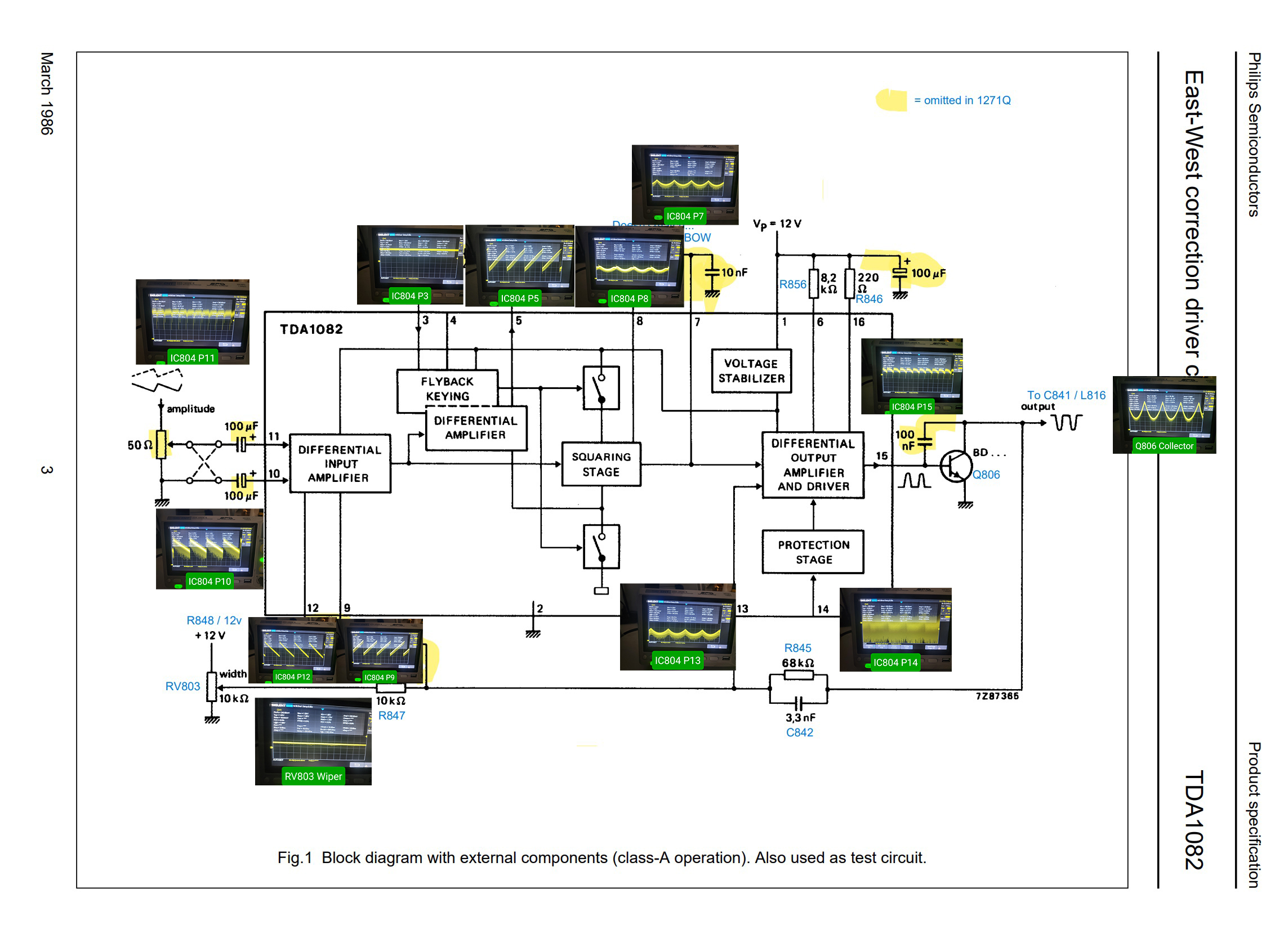


The main players here are the inputs on pin 10 and pin 11. Pin 10 is a sawtooth waveform coming from the vertical oscillator, its amplified and output from IC504. Not only does this wave need to make it all the way to IC804 pin 10, but its amplitude, offset, and all other characteristics are EXTREMELY important. If they are off even a little bit, it is enough to cause IC804 to stop outputting. The problem with all of these 1271Qs, at least my guess, is that this waveform is malformed from one or more other components failing.

When this waveform is wrong, and IC804 stops outputting, it heavily biases the entire horizontal width circuit incorrectly, which is why your raster width becomes squished and the N H WIDTH control barely does anything anymore.

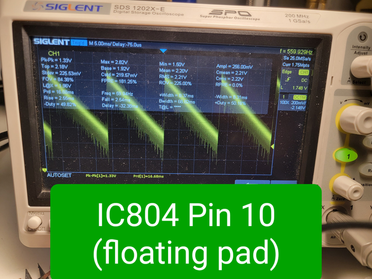
I was able to prove some of my hypothesis by desoldering ('floating") pin 10 of IC804 to take the bad waveform input out of the equation. If you do this on your bad 1271Q, and my hunch is correct, your N H WIDTH pot should start working again and you should be able to get full raster width - you just won't have any working pinamp adjustments.

One of the first things i did when starting diagnostics comparisons between a good and bad 1271Q was compare every single pin's waveforms on IC804 - so why didn't I notice anything wrong with Pin 10 early on? It seems the problems are only evident when you FLOAT THE PIN first to take it out of circuit with the rest of the pinamp circuit. This allows you to view the unaltered input waveform before it gets coupled to anything else further down the circuit. Once I did a floated pin 10 comparison between the two PVMs, the differences were obvious. The bad sawtooth waveform has what appears to be a variable DC offset, it slowly drifts up and down on my scope by several volts, and it seems very noisy/jumpy. On the good PVM, this waveform is rock-solid with no drifting or jumping.

Here is what a good pin 10 input waveform should look like when floated from the IC input (i.e. I took the measurement from the empty pad):

Generally if I see weird DC offsets I would blame a capacitor - but there are people in this thread who have already recapped their whole 1271Q and didn't solve the issue. Personally I have replaced every electrolytic (they were all within spec) and manually checked every ceramic/film capacitor on Pin 10's circuit (they were all fine) - this made absolutely no difference to the problem. Pin 10 is coupled to the VBOW/VANG circuit at C522, which I have not recapped. I suppose the problem could be down there, but those adjustments seem to be working fine and that area of the board is not particularly easily accessible so I am avoiding that for now.

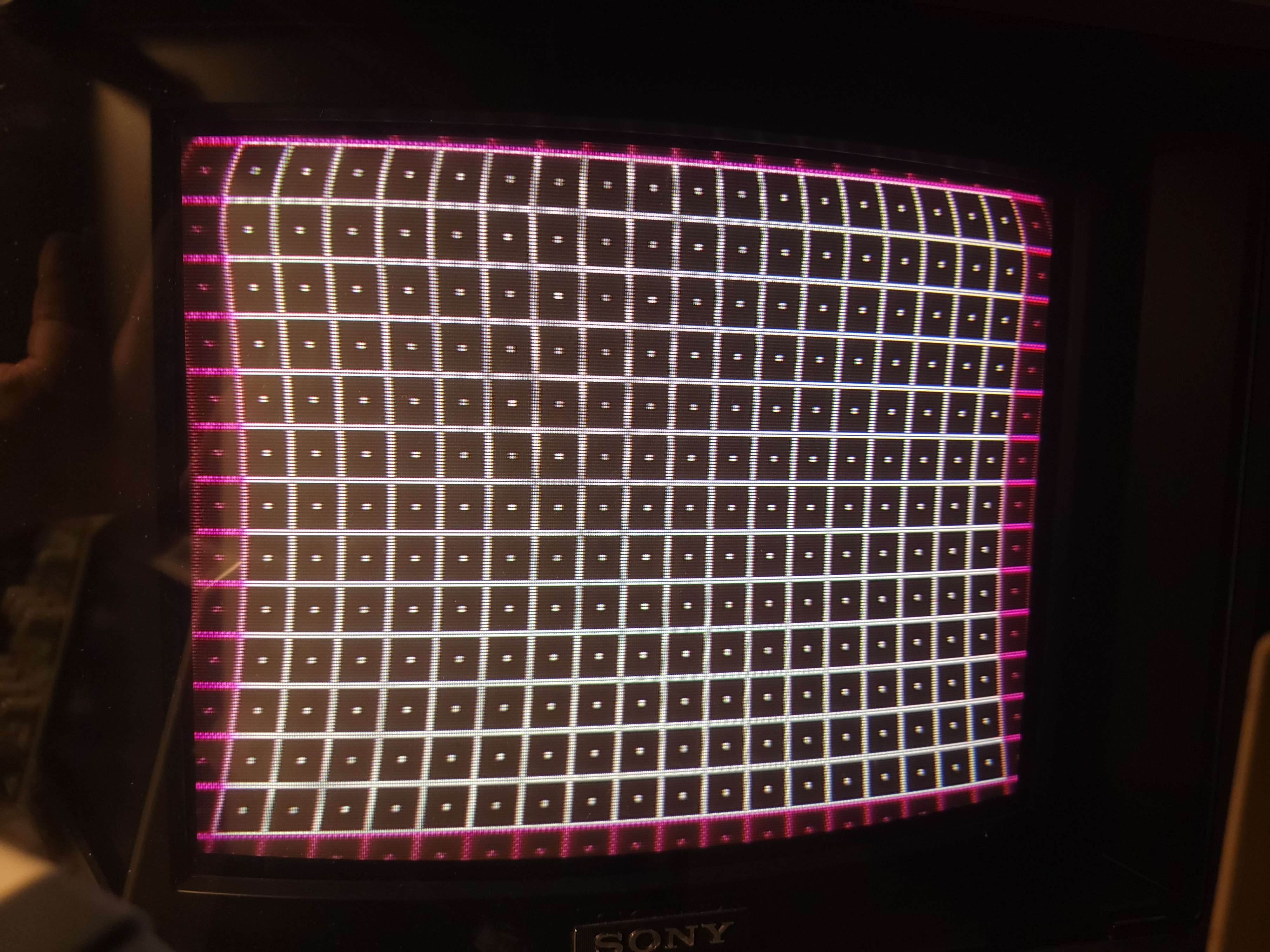
So with all of that in mind, I am pretty clueless right now on what the problem component could be here. For research purposes I actually tried to eliminate the DC offset myself by adding a ceramic capacitor in series right before Pin 10 of IC804, and the results were fascinating. Once I eliminated the DC offset, IC804 woke up and started outputting a waveform via Q806, and I was able to freely adjust N H WIDTH, PIN PHASE, and several other adjustments. The pinamp distortion improved significantly too. However, this is not a solution because the waveform, although present now, is still not correct when compared to the good PVM - and this is why the geometry is still wrong. Here is what I see on screen:


Here is what the incorrect Q806 collector waveform looks like that generated that output on the screen:
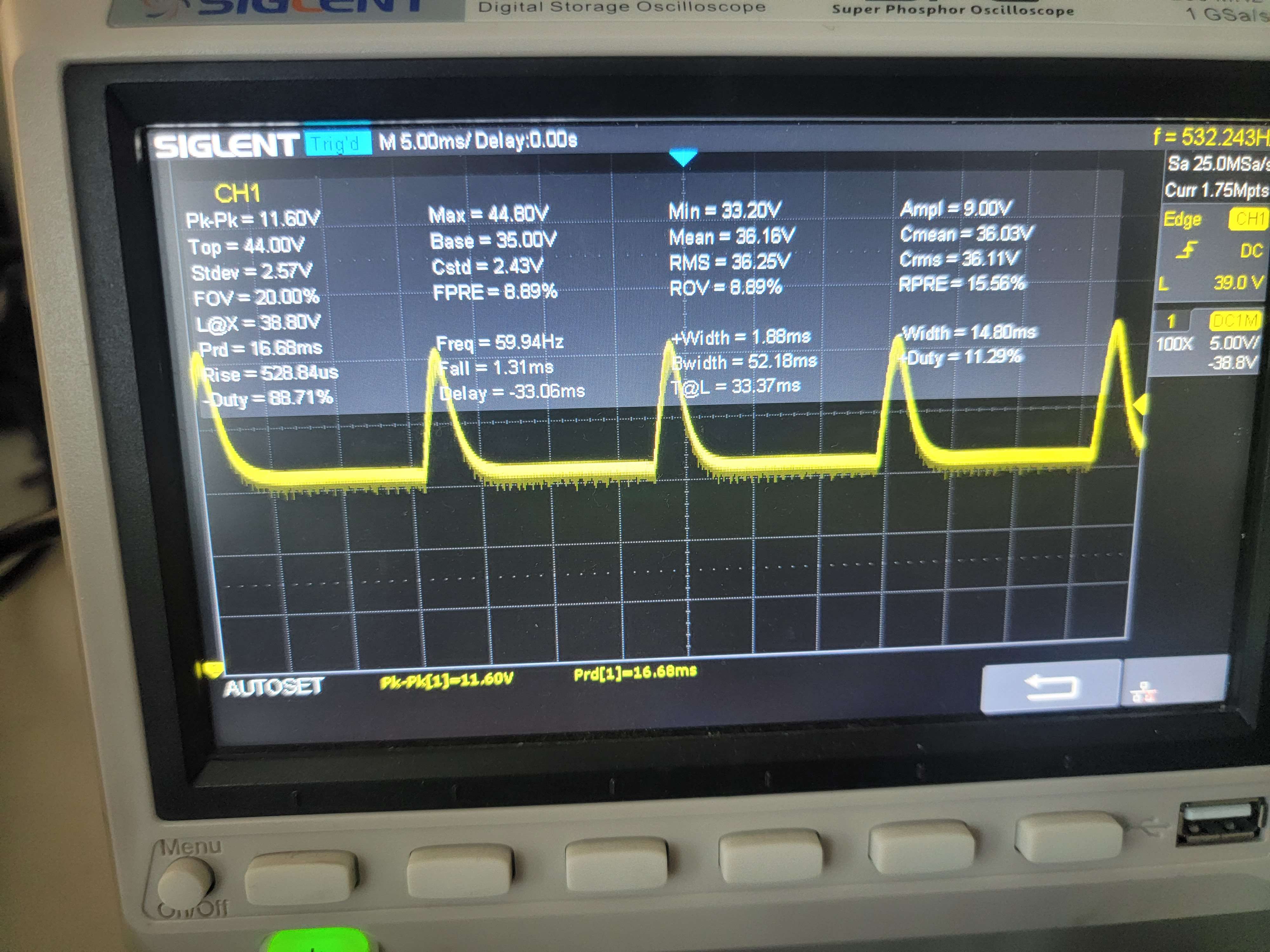


And here is what a perfect waveform at Q806 collector looks like, for reference. This is the magic sauce:
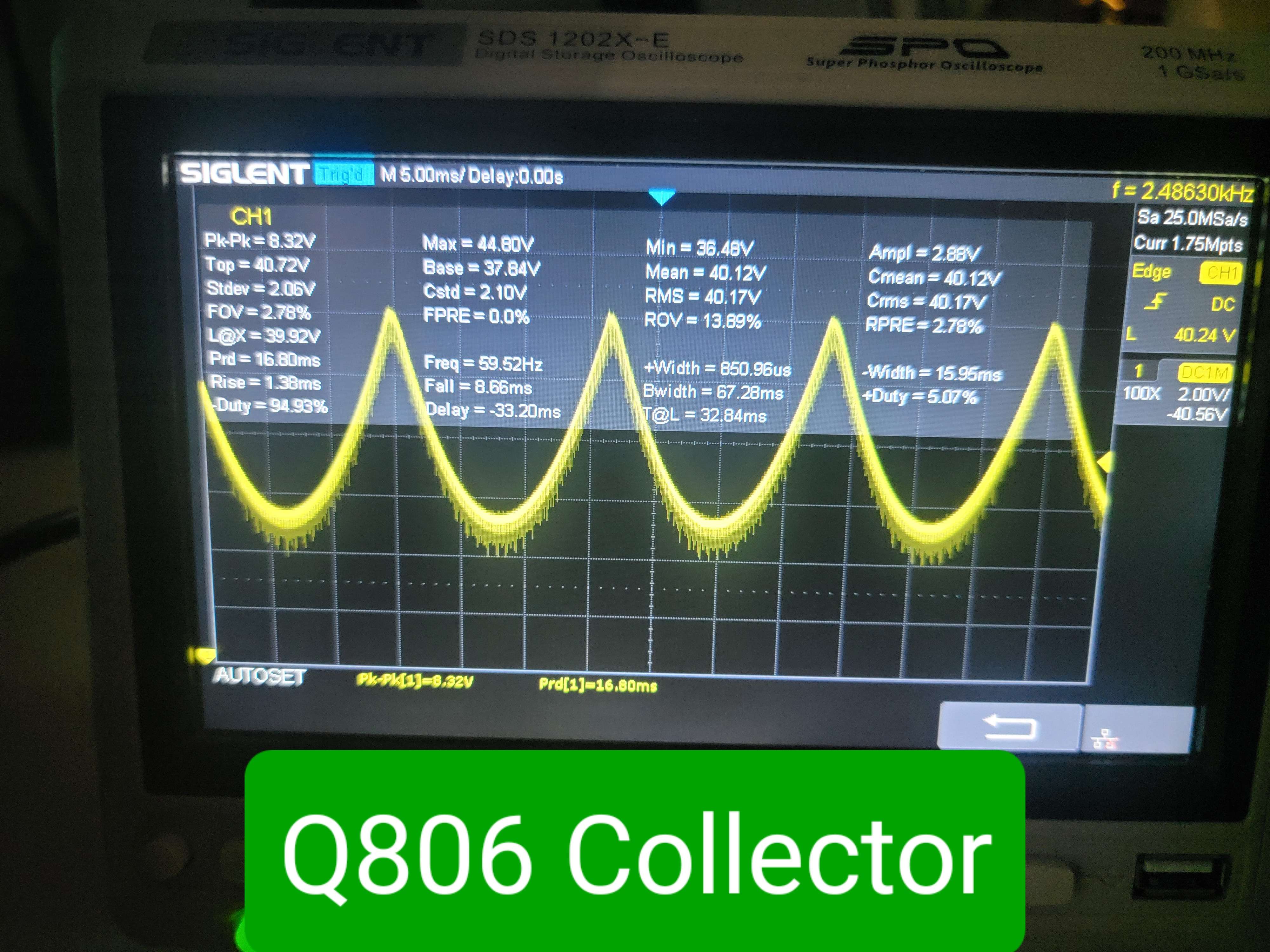
« Last Edit: November 26, 2023, 09:26:46 pm by dorksince93 »
 

Offline mattswenssonTopic starter

  • Contributor
  • Posts: 15
  • Country: us
Re: Sony PVM-1271Q
« Reply #43 on: November 26, 2023, 10:09:18 pm »
This is super helpful. I’m going to scope mine again and see what I’m getting. I have found a couple locations that don’t match the apparent spec and will report back.
 

Offline dorksince93

  • Newbie
  • Posts: 5
  • Country: us
  • CRT Database
    • CRT Database
Re: Sony PVM-1271Q
« Reply #44 on: November 26, 2023, 10:41:23 pm »
This is super helpful. I’m going to scope mine again and see what I’m getting. I have found a couple locations that don’t match the apparent spec and will report back.
That would be great. I am particularly interested in what your IC804 pin 10 waveform looks like (first normal/connected and then with the pin floated), and what your Q806 collector looks like before and after floating pin 10.

I am expecting once you float pin 10 you will be able to adjust horizontal width.

If you couple pin 10 to the input signal via a 4.7uF ceramic capacitor you'll be about where I am right now. I noticed the datasheet example circuit uses a 100uF capacitor so I'm going to give that a shot too and see how it changes the waveform. I am really curious where this 5v DC offset on my sawtooth waveform is coming from...
« Last Edit: November 26, 2023, 11:21:20 pm by dorksince93 »
 

Offline dorksince93

  • Newbie
  • Posts: 5
  • Country: us
  • CRT Database
    • CRT Database
Re: Sony PVM-1271Q
« Reply #45 on: November 27, 2023, 03:59:20 am »
Hold the phone, I just fixed the problem entirely on my 1271Q and the fix is so simple it actually physically hurts me how deep I dove into this. The N PIN AMP RV805 potentiometer on mine went bad. The literal first thing I did for diagnostics was cleaned all the pots with deoxit to rule out dirty/bad contact on the exposed surface pots but of course this pot is broken in some other physical manner that Deoxit won't fix. Its resistance has drifted from 0-330ohms range -> 100K to Megaohms range. I replaced it with a 150ohm pot I had laying around and everything immediately was corrected (to the extent 150ohms can - I need to find a full 330 range pot to correct the pinamp the remaining amount). The waveform out of Q806 looks great now, the raster width fills the whole screen, and I have control of pincushion adjustment.  :rant: :palm:

So to everyone with this problem - CHECK EVERY D BOARD POT OUT OF CIRCUIT, STARTING WITH THE N PIN AMP AND U PIN AMP. PULL THEM FROM THE BOARD AND MEASURE THEIR MIN AND MAX RANGE. If they don't fall within the range on the schematic, throw them away and get new ones. God I want the last 3 weeks of my life back  :-DD

Edit: I posted more repair info here on my website: https://crtdatabase.com/crts/sony/sony-pvm-1271q#repair-notes
« Last Edit: February 15, 2024, 09:15:36 pm by dorksince93 »
 

Offline mattswenssonTopic starter

  • Contributor
  • Posts: 15
  • Country: us
Re: Sony PVM-1271Q
« Reply #46 on: November 27, 2023, 04:53:01 am »
This is great news!  I will try this asap and report back as well.  I think/hope I have some pots that will fit!


Share me

Digg  Facebook  SlashDot  Delicious  Technorati  Twitter  Google  Yahoo
Smf