This isn't so much a how-to or a request for help in repair, but instead I thought it might provide some entertainment to share the horror that is the internals of this PC power supply. I do have a couple of questions, but they're more related to trying to understand "WTF is this?".

I originally bought this PSU around 2004 and used it in my own PC for a few years, but it then got relegated to a spare part when I upgraded, and has sat around ever since. Recently I dug it up again for use as a general-purpose +12V and +5V supply for a project. But, one day last week I turned it on to use, and after a few minutes it emitted a hissing noise and a sweet-smelling odour wafted into my nostrils. It appeared to carry on working, but I thought better of it and determined to open it up and see what happened. I suspected a leaky cap - and I was proved correct.
First, here's the culprits:


I am going to attempt to replace all these blue caps. As you can see, if they're not already leaking, they're bulging at the top.
Question: does anyone know the best way to remove that white gunk? It's not the usual kind of rubbery stuff that peels off fairly easily. It's quite hard - I can barely make a dent in it with a screwdriver tip. Maybe it was flexible when new, but has been baked hard over the years. Either way, I need to remove some of it, but not sure how.
This will be the third time now it's been in need of repair. I think it's going to become the proverbial ship of Theseus, with so many parts being replaced.

First repair was to replace one of the fans. The original failed after only one year. The plastic of the fan blades developed a crack, which meant it was no longer a tight fit over the rotating central part (I'm not sure what it's called - the bit with the windings, etc.). The centre would rotate, but the fan blades would not.
I replaced the fan myself, as the postage cost to send it back under warranty would have been half the cost of the PSU itself!
Second repair was after about 2 years. It would turn on, run for about 10 seconds, then turn off again. I had no idea what was wrong, so I gave it to my dad (a retired PSU engineer) to have a look. He said he traced it to, and replaced, a faulty IC on a daughterboard - for which he fortunately happened to have an exact replacement to hand from his old stash of parts.
I hadn't seen what he'd done until I cracked the case open today. I think it's fairly obvious which part here was replaced:


Some kind of quad voltage comparator. That part is almost as old as I am. They obviously don't make 'em like they used to!
The more I look at this PSU, the more I think I was ripped-off when I bought it. It was originally marketed as a high quality power supply, and received quite good reviews, where it apparently performed quite well. But it appears even to my inexperienced eye that this is a bit of a dog's breakfast of a power supply. It seems to me as though someone has taken an existing design and modified, added and bodged in such a way as to turn it into a 'good' PSU. But then the silkscreen on the main board says it was designed in 2003!


The build quality is horrible. There are bodge wires and components all over the place. The soldering on the bottom of the main board is fairly horrific. Everything is extremely densely packed on the main board.
Some parts of it I'm not sure of the function of. Take, for instance, this additional board:
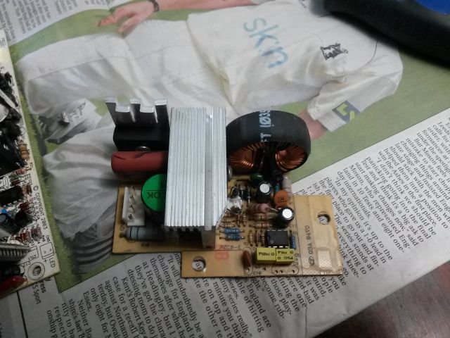
It has a four-pin connector coming off the main board, labelled 'AC', 'AC', '+V', 'GND'. I'm not sure what the its function is, apart from it taking in AC and feeding a DC voltage back out. Something to do with power factor correction judging by the presence of an 8-pin DIP marked L6561. My noob knowledge only gets me as far as tracing the AC input through a large bridge rectifier (with large cap across +/- out), then through an enormous inductor, and then branches off to three large transistors on the heatsink. Only one of them (the smallest of the three) has a pin going to the '+V' output. Apart from pin 1 of the L6561 which joins it (via a 1M resistor), nothing else on this board goes to that '+V' output.

Then there is this board directly on the mains IEC connector:
Some kind of filtering, perhaps? It features a couple of inductors, a large cap and two smaller disc-shaped ones. The large cap bridges L and N. Both L and N pass through an inductor each before going out to the switch on the back. The small caps bridge between L/N and earth.
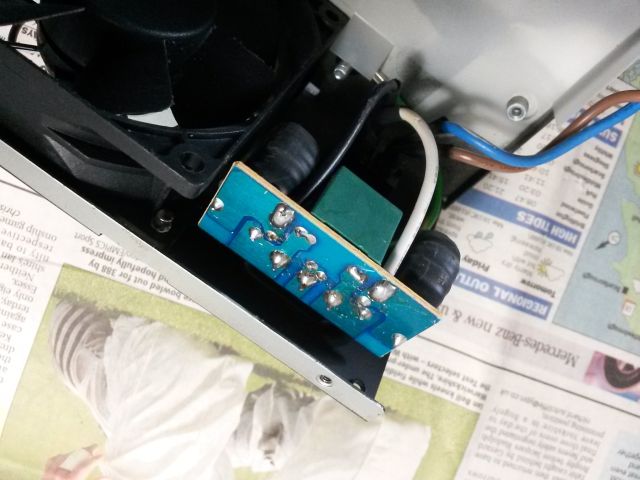
I do kind of like the way they implemented the variable-speed fan control, though. They've done it as a plug-in optional thing. Instead of directly connecting the fans to the two +12V connectors provided on the main board, they've instead ran one to a little PCB attached to one of the heatsinks. This board has (what I presume is) a thermistor attached to a tiny bit of aluminium, which nuzzles against the main heatsink to sense its temperature, and does something with a small TO-92 transistor to regulate fan speed accordingly. There are then three (one spare!) output connectors for the fans.


