Author Topic: Tektronix 465B Focus Issue  (Read 14154 times)

0 Members and 1 Guest are viewing this topic.

Offline Tomi_ETopic starter

  • Contributor
  • Posts: 10
  • Country: us
Tektronix 465B Focus Issue
« on: March 20, 2016, 01:49:20 am »
Hello, this is my first post on the EEVBlog so I've been dragging my feet until I finished reading a bit more of the Tektronix manual.  While also exploring other repair posts that might help with my scopes fault. I'm a bit of a novice with more complex electronics even though I took a few electronic classes in collage.  I even built a basic Theremin from scratch as a very successful birthday gift. So I would say I know enough to stay safe and double check myself before testing anything in this scope. But at best I'm still just a self taught hobbyist.

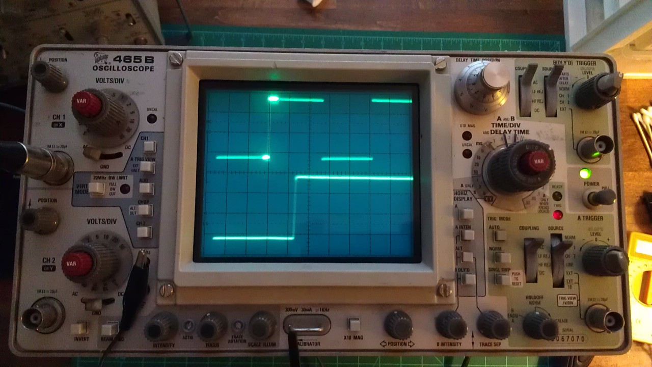
I bought this scope on ebay as not working with no trace. After winning the offer I started to think that it was a mistake and I was now the owner of a boat anchor. Thankfully in less then 5 minutes of tinkering I was able to get a trace. This Tektronix 465B was eager to show it's stuff and that was a huge relief. Now starts the fun part, cleaning and fixing this Tek.

Besides some Dirty contacts the only other issue I can see is bad focus. Also the Intensity seems a little too touchy to me.


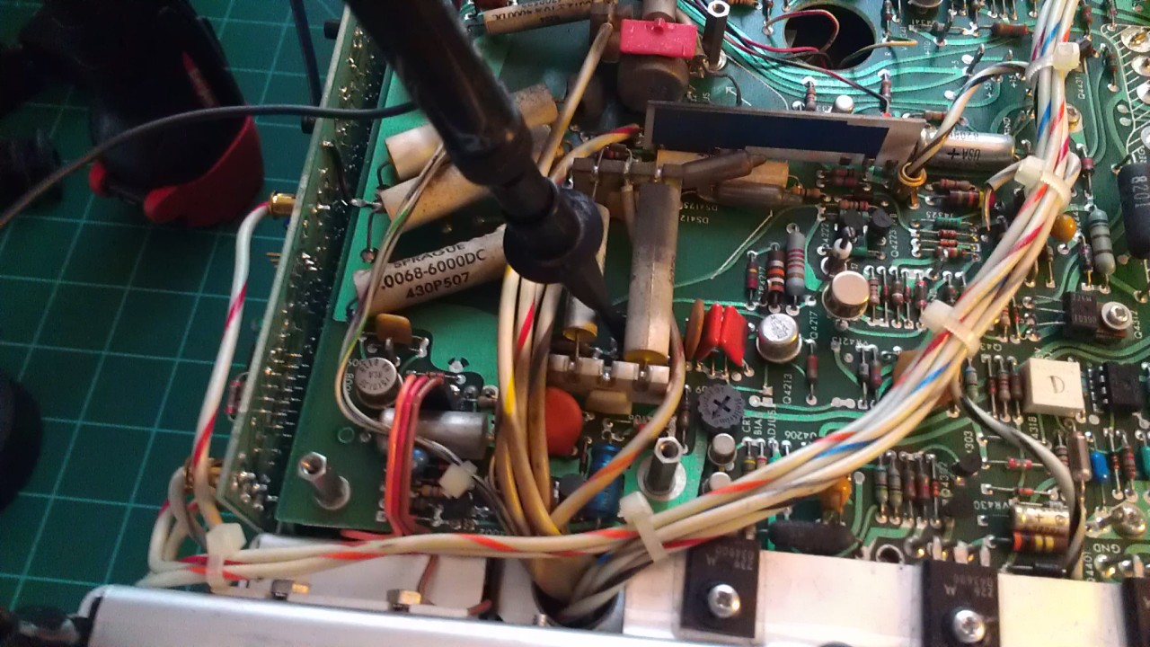
Looking in the manual I can see there are some test points and wave forms I can check... Under the high voltage cover plate. Oh boy.


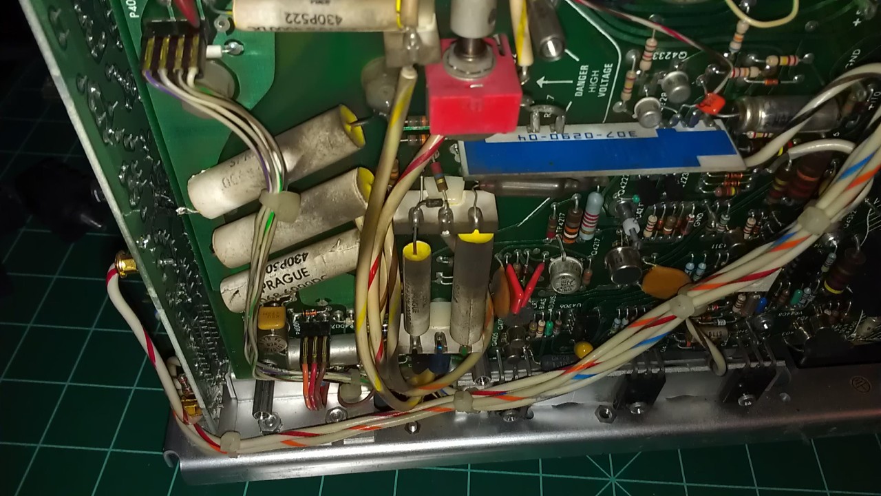
It's a bit dirty under there and from what I read in Tek Troubleshooting PDF That dust can cause leakage. So I will be cleaning that section... very carefully.
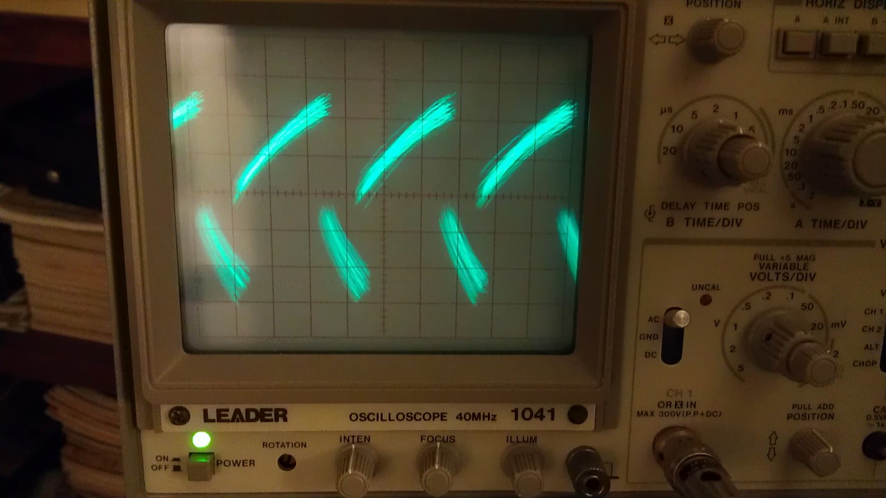
http://www.sphere.bc.ca/test/tek-parts/troubleshooting-scopes.pdf

I'm unsure that the dust could cause the issue though. I hooked up my working Leader scope to Test point 93 shown in the CRT Circuit schematic and the waveform looks ok. Until I adjust the intensity and this happens.


I was a bit nervous hooking up my scope because the test point is under the high voltage caps. So I unplugged the scope, connected the probe one handed, and then plugged it back in and turned it on. Being extra careful to use only one hand and keep away from the high voltage.


So at the moment I'm a bit stuck. Did I measure test point 93 correctly? Is it possible that my probe is giving this weird signal? Part of the signal looks like the waveform in the manual but why the unchanging signal when the intensity is turned?

Knowing that both of my cheap multimeters are only to be used as paper weights, I went on the hunt for a DMM with better specs than what the manual calls for.  Having found a Keithley 178 I checked the voltage rails and they seem to be in spec with the manual.  Though I'm sure my Keithley should be calibrated, it's still a whole lot better then those cheap multimeters.

I tested the -2450 volts with a working triplett 630 NA. It was spot on. The manual recommended the Triplett 630-NA so I gave in and bought one. I was very careful testing the high voltage following the Triplett manual. Hooked it up with the scope unplugged, then plugged the scope back in and with one hand turned the scope on. I must admit I was nervous about using this old meter but rather pleased that it worked flawlessly. Also I did check the meter to make sure it was clean both inside and out before even thinking about using it to test the high voltage. I did not want to damage my new favorite tool.  ^-^ Also I was able to test the Keithley against the Triplett and was rather surprised they complemented each other.  Yes it's analog against digital, but still I rather like my new tools. They instill more confidence then any cheep multimeter out there.

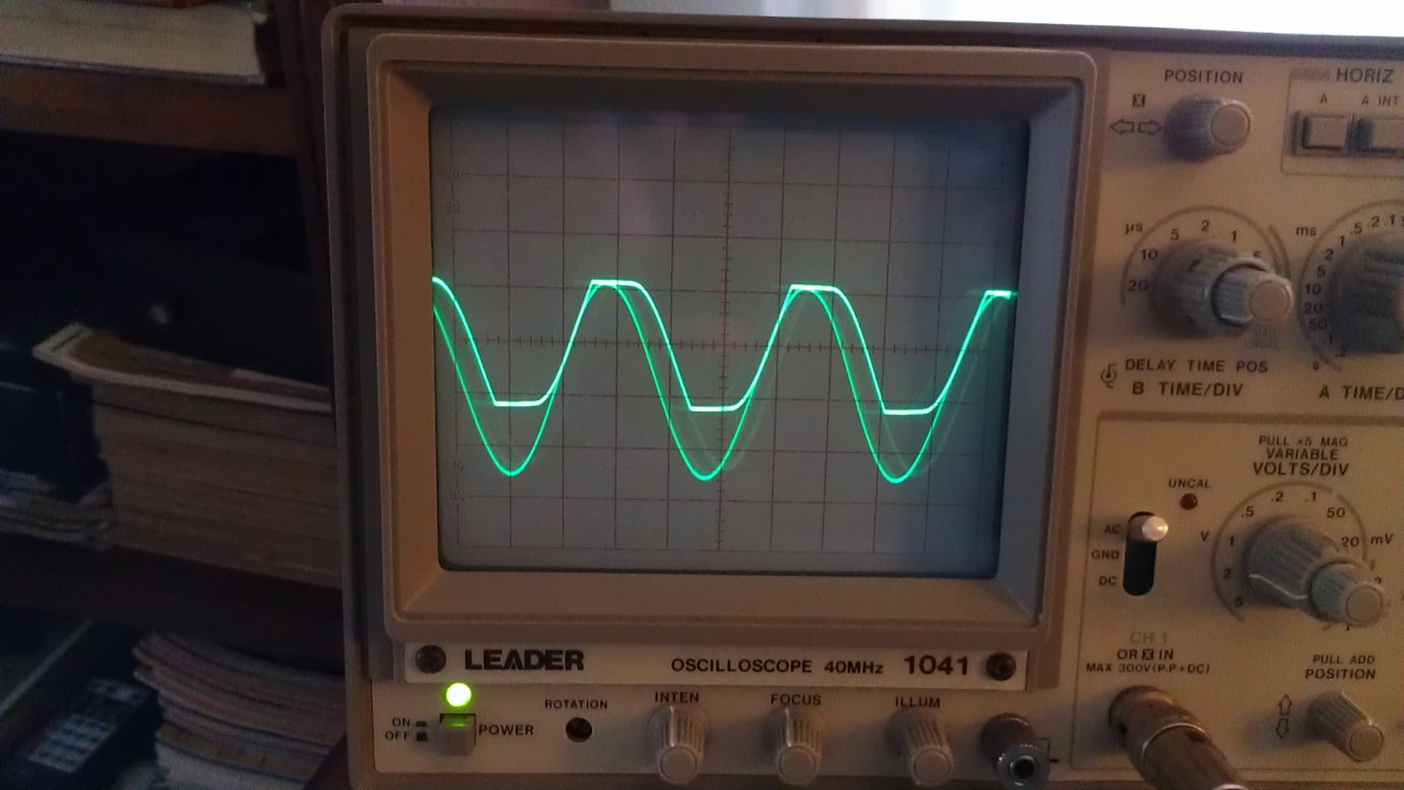
The CRT Bias was checked/set to the adjustment procedure outlined in the manual. It seems to work as it should and measures fine with a scope hooked up to TP4217.  Although maybe an experienced eye can spot something in the trace... hmm ok, I just checked it and this is something I didn't notice before. While adjusting the intensity I got this at TP4217. That can't be good, and this changes where I should look in the schematic. Bad caps I hope?


Offline Tomi_ETopic starter

  • Contributor
  • Posts: 10
  • Country: us
Re: Tektronix 465B Focus Issue
« Reply #1 on: March 20, 2016, 02:44:49 am »
Looks like I need some new Probes, The old one is giving false signals. :(
 

Offline tautech

  • Super Contributor
  • ***
  • Posts: 28335
  • Country: nz
  • Taupaki Technologies Ltd. Siglent Distributor NZ.
    • Taupaki Technologies Ltd.
Re: Tektronix 465B Focus Issue
« Reply #2 on: March 20, 2016, 02:45:04 am »
Welcome to the forum.
Nice first post.  :-+

You say you've checked the PSU rails as "spot on" but did you check for ripple, you have another CRO so that'd be easy. Use AC input coupling and mV ranges.

Getting the PSU exactly within spec is always the first step for repairs.
Avid Rabid Hobbyist
Siglent Youtube channel: https://www.youtube.com/@SiglentVideo/videos
 

Offline Tomi_ETopic starter

  • Contributor
  • Posts: 10
  • Country: us
Re: Tektronix 465B Focus Issue
« Reply #3 on: March 20, 2016, 03:16:02 am »
Hello and thank you tautech ^-^

Yes I was able to check for ripple on all the rails and as far as I could tell there is hardly anything. The +110V shows less then the 20mV ripple stated in the manual.
 

Offline Tomi_ETopic starter

  • Contributor
  • Posts: 10
  • Country: us
Re: Tektronix 465B Focus Issue
« Reply #4 on: March 24, 2016, 06:02:51 pm »
The New probes just arrived today.  Having more then one probe has helped me to understand what I was looking at. As far as I can tell that part of the circuit is working as it should.  I tested voltages on a few more connections to the CRT and they all look fine.

So my next step is to check the horizontal and vertical sections.

Waveform 93 on top and TP4217 on the bottom.


Cleaned up most of the dust.
« Last Edit: March 28, 2016, 07:16:57 pm by Tomi_E »
 

Offline tggzzz

  • Super Contributor
  • ***
  • Posts: 19470
  • Country: gb
  • Numbers, not adjectives
    • Having fun doing more, with less
Re: Tektronix 465B Focus Issue
« Reply #5 on: March 24, 2016, 06:45:47 pm »
I recently resurrected a 465, with the help of the denizens in the Yahoo! TecScopes group. I suggest you join that group, search the archives and then ask any remaining questions.
There are lies, damned lies, statistics - and ADC/DAC specs.
Glider pilot's aphorism: "there is no substitute for span". Retort: "There is a substitute: skill+imagination. But you can buy span".
Having fun doing more, with less
 

Offline Tomi_ETopic starter

  • Contributor
  • Posts: 10
  • Country: us
Re: Tektronix 465B Focus Issue
« Reply #6 on: March 27, 2016, 08:03:27 am »
Thank you tggzzz, I'm surprised at how much info that yahoo group has. Also how active it is! ^-^

If I'm measuring the ripple on the 110 volt rail correctly, using my probes on X1, 20mV/Div AC coupled... Then it is within the 20mV Typical, correct me if I'm wrong. Also I did watch Dave's video on measuring power supply ripple & noise again.  Hmm, unless my working scope is way off.  :palm:

I have having fun with this though. The more I tinker with this analog scope the more I learn  :D


Offline tautech

  • Super Contributor
  • ***
  • Posts: 28335
  • Country: nz
  • Taupaki Technologies Ltd. Siglent Distributor NZ.
    • Taupaki Technologies Ltd.
Re: Tektronix 465B Focus Issue
« Reply #7 on: March 27, 2016, 08:41:53 am »
Quote
Hmm, unless my working scope is way off.
Of most concern for ripple levels are the low voltage rails, those must be within spec.

One use of the probe Cal output is a sanity check, ie. you've set the CRO correctly; trigger, V/div, coupling etc.
However the Cal output is not a "precision" waveform, but frequency and amplitude accuracy is near enough for basic checks.
So you could check the probe Cal outputs of each scope on the other and vice versa, any little thing you can safely probe gains experience and confidence. For now stick with LV stuff.  ;)

With CRO's it's imperative  to set V/div settings as to have the waveform amplitude within the confines of the display, failure to do so overloads the CRT plate amps and can lead to early failures.
Avid Rabid Hobbyist
Siglent Youtube channel: https://www.youtube.com/@SiglentVideo/videos
 

Offline tggzzz

  • Super Contributor
  • ***
  • Posts: 19470
  • Country: gb
  • Numbers, not adjectives
    • Having fun doing more, with less
Re: Tektronix 465B Focus Issue
« Reply #8 on: March 27, 2016, 08:58:51 am »
Quote
Hmm, unless my working scope is way off.
One use of the probe Cal output is a sanity check, ie. you've set the CRO correctly; trigger, V/div, coupling etc.
However the Cal output is not a "precision" waveform, but frequency and amplitude accuracy is near enough for basic checks.

As I'm sure you know, the prime use of the cal out is for low-frequency tweaking of *10 probes. As you say, the amplitude and frequency are not well controlled.

OTOH I was surprised to find my 485's cal out is both 1kHz and 1MHz, 5V open circuit, 450ohms output impedance. The frequencies and amplitude are tweaked by trimpots.

The 450ohm impedance is important since when connected directly to the scope's 50ohm input, it forms an impedance matched 10:1 divider with a sub-nanosecond risetime.
There are lies, damned lies, statistics - and ADC/DAC specs.
Glider pilot's aphorism: "there is no substitute for span". Retort: "There is a substitute: skill+imagination. But you can buy span".
Having fun doing more, with less
 

Offline tautech

  • Super Contributor
  • ***
  • Posts: 28335
  • Country: nz
  • Taupaki Technologies Ltd. Siglent Distributor NZ.
    • Taupaki Technologies Ltd.
Re: Tektronix 465B Focus Issue
« Reply #9 on: March 27, 2016, 09:05:54 am »
Quote
Hmm, unless my working scope is way off.
One use of the probe Cal output is a sanity check, ie. you've set the CRO correctly; trigger, V/div, coupling etc.
However the Cal output is not a "precision" waveform, but frequency and amplitude accuracy is near enough for basic checks.

As I'm sure you know, the prime use of the cal out is for low-frequency tweaking of *10 probes. As you say, the amplitude and frequency are not well controlled.

OTOH I was surprised to find my 485's cal out is both 1kHz and 1MHz, 5V open circuit, 450ohms output impedance. The frequencies and amplitude are tweaked by trimpots.

The 450ohm impedance is important since when connected directly to the scope's 50ohm input, it forms an impedance matched 10:1 divider with a sub-nanosecond risetime.
Hell that's fast.  8)
When you say 1 KHz and 1 MHz, how's that accomplished?
Does the 485 also have the Cal bar so that one can check a current probe too?
Avid Rabid Hobbyist
Siglent Youtube channel: https://www.youtube.com/@SiglentVideo/videos
 

Offline tggzzz

  • Super Contributor
  • ***
  • Posts: 19470
  • Country: gb
  • Numbers, not adjectives
    • Having fun doing more, with less
Re: Tektronix 465B Focus Issue
« Reply #10 on: March 27, 2016, 09:41:58 am »
Quote
Hmm, unless my working scope is way off.
One use of the probe Cal output is a sanity check, ie. you've set the CRO correctly; trigger, V/div, coupling etc.
However the Cal output is not a "precision" waveform, but frequency and amplitude accuracy is near enough for basic checks.

As I'm sure you know, the prime use of the cal out is for low-frequency tweaking of *10 probes. As you say, the amplitude and frequency are not well controlled.

OTOH I was surprised to find my 485's cal out is both 1kHz and 1MHz, 5V open circuit, 450ohms output impedance. The frequencies and amplitude are tweaked by trimpots.

The 450ohm impedance is important since when connected directly to the scope's 50ohm input, it forms an impedance matched 10:1 divider with a sub-nanosecond risetime.
Hell that's fast.  8)

And very clean. ISTR that it inspired a Jim Williams circuit, but that may be a faulty neuron firing.

Quote
When you say 1 KHz and 1 MHz, how's that accomplished?

Think ECL :) See below.

Quote
Does the 485 also have the Cal bar so that one can check a current probe too?

No.
« Last Edit: March 27, 2016, 09:43:42 am by tggzzz »
There are lies, damned lies, statistics - and ADC/DAC specs.
Glider pilot's aphorism: "there is no substitute for span". Retort: "There is a substitute: skill+imagination. But you can buy span".
Having fun doing more, with less
 

Offline tautech

  • Super Contributor
  • ***
  • Posts: 28335
  • Country: nz
  • Taupaki Technologies Ltd. Siglent Distributor NZ.
    • Taupaki Technologies Ltd.
Re: Tektronix 465B Focus Issue
« Reply #11 on: March 27, 2016, 09:50:33 am »
Quote
Hmm, unless my working scope is way off.
One use of the probe Cal output is a sanity check, ie. you've set the CRO correctly; trigger, V/div, coupling etc.
However the Cal output is not a "precision" waveform, but frequency and amplitude accuracy is near enough for basic checks.

As I'm sure you know, the prime use of the cal out is for low-frequency tweaking of *10 probes. As you say, the amplitude and frequency are not well controlled.

OTOH I was surprised to find my 485's cal out is both 1kHz and 1MHz, 5V open circuit, 450ohms output impedance. The frequencies and amplitude are tweaked by trimpots.

The 450ohm impedance is important since when connected directly to the scope's 50ohm input, it forms an impedance matched 10:1 divider with a sub-nanosecond risetime.
Hell that's fast.  8)

And very clean. ISTR that it inspired a Jim Williams circuit, but that may be a faulty neuron firing.
Of course, Tek made nice gear back then.

Thanks for the full reply, I see the either of the 2 frequencies were switched in or out.  8)
Avid Rabid Hobbyist
Siglent Youtube channel: https://www.youtube.com/@SiglentVideo/videos
 

Offline tggzzz

  • Super Contributor
  • ***
  • Posts: 19470
  • Country: gb
  • Numbers, not adjectives
    • Having fun doing more, with less
Re: Tektronix 465B Focus Issue
« Reply #12 on: March 27, 2016, 10:26:33 am »
Of course, Tek made nice gear back then.

Yes and no.

I had to pull apart my HP1740a, and found the interior to be as clean and easy to maintain as I expected. The only exception was the bit I had to repair, where rotating the timebase control had abraded the PCB track (not the contact) to the point at which it had disappeared. The Tek contacts are better in that respect. I'll deliberately forget that in order to get the 3.5ns risetime you occasionally have to fondle and massage the delay line!

OTOH, I was unpleasantly surprised to see the build construction of the Tek 465. Many ordinary components such as diodes and resistor bridged in mid-air, as if they has modded the design without changing the PCB. To remove some PCBs, several wires have to be de-soldered, the delay line being the worst. Painful. I'm not surprised they had to introduce a militarised version, the 465M.

The Tek 485 construction is much better in those respects.

There are lies, damned lies, statistics - and ADC/DAC specs.
Glider pilot's aphorism: "there is no substitute for span". Retort: "There is a substitute: skill+imagination. But you can buy span".
Having fun doing more, with less
 

Offline tggzzz

  • Super Contributor
  • ***
  • Posts: 19470
  • Country: gb
  • Numbers, not adjectives
    • Having fun doing more, with less
Re: Tektronix 465B Focus Issue
« Reply #13 on: March 27, 2016, 10:32:40 am »
Thank you tggzzz, I'm surprised at how much info that yahoo group has. Also how active it is! ^-^

I have having fun with this though. The more I tinker with this analog scope the more I learn  :D

You're welcome.

Be careful you don't become addicted. Next you'll need a 350MHz 485 so you can see a 1ns risetime when investigating signal integrity problems on "digital" signals :)

Don't forget to spend money on probes, and to understand their limitations - especially so-called "high impedance" *10 probes.
There are lies, damned lies, statistics - and ADC/DAC specs.
Glider pilot's aphorism: "there is no substitute for span". Retort: "There is a substitute: skill+imagination. But you can buy span".
Having fun doing more, with less
 

Offline Tomi_ETopic starter

  • Contributor
  • Posts: 10
  • Country: us
Re: Tektronix 465B Focus Issue
« Reply #14 on: March 27, 2016, 11:13:07 am »
So you could check the probe Cal outputs of each scope on the other and vice versa, any little thing you can safely probe gains experience and confidence. For now stick with LV stuff.  ;)

I did check both scopes against each other using the cal outputs. Even with the fuzzy trace on the 465B they both complement each other. Although the 465B shows a flatter response to the square wave then the Leader. The Leader could use a little calibration in the future.  ^-^

My next thought was to hunt down a high voltage oscilloscope probe and see if the HV is clean.  But I'm wondering if a home built ESR would be faster for testing the HV caps. ;D

With CRO's it's imperative  to set V/div settings as to have the waveform amplitude within the confines of the display, failure to do so overloads the CRT plate amps and can lead to early failures.

That is something I did not know. Is that also true without a signal on the scope and the trace moved off screen?

Thank you tggzzz, I'm surprised at how much info that yahoo group has. Also how active it is! ^-^

I have having fun with this though. The more I tinker with this analog scope the more I learn  :D

You're welcome.

Be careful you don't become addicted. Next you'll need a 350MHz 485 so you can see a 1ns risetime when investigating signal integrity problems on "digital" signals :)

Don't forget to spend money on probes, and to understand their limitations - especially so-called "high impedance" *10 probes.

It might be too late for me. I'm already enjoying my triplett 630-na more then I should. Also the attraction of owning an all tube tek scope is almost irresistible. A 485 you say? Hmm I'm going to google that. lol 

My hopes are if I can get this 465B working I'll buy a better pair of probes from Avex with the x10 readout feature.  For now, I have more scope than I could ever need. xD
 

Offline tautech

  • Super Contributor
  • ***
  • Posts: 28335
  • Country: nz
  • Taupaki Technologies Ltd. Siglent Distributor NZ.
    • Taupaki Technologies Ltd.
Re: Tektronix 465B Focus Issue
« Reply #15 on: March 27, 2016, 11:27:47 am »
So you could check the probe Cal outputs of each scope on the other and vice versa, any little thing you can safely probe gains experience and confidence. For now stick with LV stuff.  ;)

I did check both scopes against each other using the cal outputs. Even with the fuzzy trace on the 465B they both complement each other. Although the 465B shows a flatter response to the square wave then the Leader. The Leader could use a little calibration in the future.  ^-^

My next thought was to hunt down a high voltage oscilloscope probe and see if the HV is clean.  But I'm wondering if a home built ESR would be faster for testing the HV caps. ;D

With CRO's it's imperative  to set V/div settings as to have the waveform amplitude within the confines of the display, failure to do so overloads the CRT plate amps and can lead to early failures.

That is something I did not know. Is that also true without a signal on the scope and the trace moved off screen?
Yes but less so.

Electrostatic deflection requires the plate output amps to swing close to the HV rails in order to provide the plate voltages to induce sufficient deflection to cover the vertical range of the CRT. The plate voltages when a trace is centered is ~1/2 of the available HV on each plate and in order to deflect the beam off screen one plate will have nearly all the HV available on it while the other will be low.
Old transistors don't like this much, especially when there's barely enough voltage headroom allowed for in the original design.
Use a CRO wisely and it'll serve you well.  ;)


Avid Rabid Hobbyist
Siglent Youtube channel: https://www.youtube.com/@SiglentVideo/videos
 

Offline tggzzz

  • Super Contributor
  • ***
  • Posts: 19470
  • Country: gb
  • Numbers, not adjectives
    • Having fun doing more, with less
Re: Tektronix 465B Focus Issue
« Reply #16 on: March 27, 2016, 12:07:15 pm »
So you could check the probe Cal outputs of each scope on the other and vice versa, any little thing you can safely probe gains experience and confidence. For now stick with LV stuff.  ;)

I did check both scopes against each other using the cal outputs. Even with the fuzzy trace on the 465B they both complement each other. Although the 465B shows a flatter response to the square wave then the Leader. The Leader could use a little calibration in the future.  ^-^

Caution. If using a probe then you are seeing the performance of the scope+probe; don't adjust the scope to get best performance from scope+probe! Ideally you want a signal generator with a <1ns risetime attached directly to the scope input; if necessary, use a BNC T-piece plus a 50ohm terminator.

Read the service manual to see how to adjust scopes. The fundamental principles will be similar across all scopes, even if you tweak different pots in different orders.

Quote
My next thought was to hunt down a high voltage oscilloscope probe and see if the HV is clean.  But I'm wondering if a home built ESR would be faster for testing the HV caps. ;D

HV probes are expensive and have limitations, and I haven't got one. Work out exactly what you need to measure and why. If necessary, use some ingenuity - but check any HV ideas with other people before implementing them. Obviously you will get a better response if you say "I think A because B, so I want to measure Y using Z".

I'm not sure ESR is a key failure mode in HV caps. The general recommendation is to simply replace them all together with the HV diodes. See https://www.eevblog.com/forum/repair/tek-485-repair-and-restoration-prologue/ for a BoM in a 485.

Having said that, replacing the HV diodes was a waste of time in my 465 since the problem was inside the CRT. (FFI, see my posting in TekScopes)

Quote
Thank you tggzzz, I'm surprised at how much info that yahoo group has. Also how active it is! ^-^

I have having fun with this though. The more I tinker with this analog scope the more I learn  :D

You're welcome.

Be careful you don't become addicted. Next you'll need a 350MHz 485 so you can see a 1ns risetime when investigating signal integrity problems on "digital" signals :)

Don't forget to spend money on probes, and to understand their limitations - especially so-called "high impedance" *10 probes.

It might be too late for me. I'm already enjoying my triplett 630-na more then I should. Also the attraction of owning an all tube tek scope is almost irresistible. A 485 you say? Hmm I'm going to google that. lol 

My hopes are if I can get this 465B working I'll buy a better pair of probes from Avex with the x10 readout feature. 

Make sure you understand what "better" might mean in different circumstances. I've put a mixture of theory, practical and safety references at https://entertaininghacks.wordpress.com/library-2/scope-probe-reference-material/

Quote
For now, I have more scope than I could ever need. xD

... but for how long :)
There are lies, damned lies, statistics - and ADC/DAC specs.
Glider pilot's aphorism: "there is no substitute for span". Retort: "There is a substitute: skill+imagination. But you can buy span".
Having fun doing more, with less
 

Offline tggzzz

  • Super Contributor
  • ***
  • Posts: 19470
  • Country: gb
  • Numbers, not adjectives
    • Having fun doing more, with less
Re: Tektronix 465B Focus Issue
« Reply #17 on: March 28, 2016, 02:31:35 pm »
I hooked up my working Leader scope to Test point 93 shown in the CRT Circuit schematic and the waveform looks ok. Until I adjust the intensity and this happens.

What/where is TP93 (my manual isn't searchable), and what are the voltages displayed in the image, particularly the clipping voltages?
There are lies, damned lies, statistics - and ADC/DAC specs.
Glider pilot's aphorism: "there is no substitute for span". Retort: "There is a substitute: skill+imagination. But you can buy span".
Having fun doing more, with less
 

Offline Tomi_ETopic starter

  • Contributor
  • Posts: 10
  • Country: us
Re: Tektronix 465B Focus Issue
« Reply #18 on: March 28, 2016, 07:01:05 pm »
I hooked up my working Leader scope to Test point 93 shown in the CRT Circuit schematic and the waveform looks ok. Until I adjust the intensity and this happens.

What/where is TP93 (my manual isn't searchable), and what are the voltages displayed in the image, particularly the clipping voltages?

In the manual 93 is shown in Fig 8-10 Interface circuit board adjustment locations.  It's one side of the diodes CR4111 and CR4112 under the two HV Caps. The PDF I have shows the location on page 263 if that helps. The waveforms were missing from my pdf but I was able to find the missing pages. It's not really called TP 93, it's just labeled 93 on the CRT schematic. ^-^ I should of worded that differently. The upper part of the waveform is ~98V and varies with the CRT Bias setting. The bottom part of the waveform starts to clip when the intensity is increased at around 20V.


Offline tggzzz

  • Super Contributor
  • ***
  • Posts: 19470
  • Country: gb
  • Numbers, not adjectives
    • Having fun doing more, with less
Re: Tektronix 465B Focus Issue
« Reply #19 on: March 28, 2016, 07:21:19 pm »
I hooked up my working Leader scope to Test point 93 shown in the CRT Circuit schematic and the waveform looks ok. Until I adjust the intensity and this happens.

What/where is TP93 (my manual isn't searchable), and what are the voltages displayed in the image, particularly the clipping voltages?

In the manual 93 is shown in Fig 8-10 Interface circuit board adjustment locations.  It's one side of the diodes CR4111 and CR4112 under the two HV Caps. The PDF I have shows the location on page 263 if that helps. The waveforms were missing from my pdf but I was able to find the missing pages. It's not really called TP 93, it's just labeled 93 on the CRT schematic. ^-^ I should of worded that differently. The upper part of the waveform is ~98V and varies with the CRT Bias setting. The bottom part of the waveform starts to clip when the intensity is increased at around 20V.

Sorry, I can't locate any of those in the manuals available to me.
There are lies, damned lies, statistics - and ADC/DAC specs.
Glider pilot's aphorism: "there is no substitute for span". Retort: "There is a substitute: skill+imagination. But you can buy span".
Having fun doing more, with less
 

Offline Tomi_ETopic starter

  • Contributor
  • Posts: 10
  • Country: us
Re: Tektronix 465B Focus Issue
« Reply #20 on: March 28, 2016, 10:44:19 pm »
No need to be sorry tggzzz you have already helped me greatly!

This is the manual and missing pages I have http://bama.edebris.com/manuals/tek/465b/
PDF Pages 248, 253, and 263.

And some quick screen shots ^-^


Offline tggzzz

  • Super Contributor
  • ***
  • Posts: 19470
  • Country: gb
  • Numbers, not adjectives
    • Having fun doing more, with less
Re: Tektronix 465B Focus Issue
« Reply #21 on: March 29, 2016, 12:21:01 am »
Caution: this is late at night, so I might regret posting it tomorrow.

You have a 465B, I have a 465; that's the source of my incompetence.

Having said that, these two circuits are very similar, which is unsurprising since the CRTs are the same. That implies there might be useful explanations in the older manual.

From memory..., the waveform at 91/TP4217 is the key waveform to do with the intensity and blanking and unblanking the CRT. The operation of the whole of this circuit is to translate the AC part of that waveform up to the cathode voltage, and add a DC component based on the grid bias pot. If you could measure the grid-cathode voltage, you should see exactly the same as at TP4217 - but that is tricky since Vk is ~-3kV.
Considering waveform 93. The waveform on the other side of C4010 is a 300Vpp sinewave; see the 465 manual. The upper value of waveform 93 is a clipped version of that, where the clipping voltage is the CRT bias voltage + 75V (R4109 + VR4108).

However it looks like all that is fundamentally working; your first picture of the intensified trace looks sensible from the brightness point of view. If there is any "touchyness" then I would suspect contact noise in the front-panel brightness pot, or in R4109. If the brightness varies "on it own", then I would consider one of the HV components at fault - traditionally the ">1kV" capacitors or the HV diodes in that area.

I'm not sure why your big white Sprague HV capacitors are discoloured towards one end - dirt? Breakdown?

I'd also have a look at all the resistors in that area to see if any look different in any way, e.g. burns, or they have been replaced with a non-HV variant. Or maybe just aged or even cracked (poke them with a toothpick to see if cracks can be opened.

As for focus, the waveforms in this area shouldn't affect it very much. As long as the voltage on CRT grid (pin 4) is at the right value and there isn't noise, I don't think there is much you can do. Is the focus best in the middle of the focus control's range? Have you adjusted the astigmatism? Use a low intensity, and x-y mode to get a single spot near the screen centre before tweaking.

However, you would be unwise to rely on me for understanding of CRT operation.

Apart from that, if you have a subtly faulty probe then the best course of action is to save all its probe accessories and then cut the probe up to see what's inside. Similarly never leave untrustworthy coax around!
There are lies, damned lies, statistics - and ADC/DAC specs.
Glider pilot's aphorism: "there is no substitute for span". Retort: "There is a substitute: skill+imagination. But you can buy span".
Having fun doing more, with less
 

Offline Tomi_ETopic starter

  • Contributor
  • Posts: 10
  • Country: us
Re: Tektronix 465B Focus Issue
« Reply #22 on: March 30, 2016, 09:50:54 pm »
I'm not sure why your big white Sprague HV capacitors are discoloured towards one end - dirt? Breakdown?

I believe it was just dirt, the caps cleaned up nicely.

As for focus, the waveforms in this area shouldn't affect it very much. As long as the voltage on CRT grid (pin 4) is at the right value and there isn't noise, I don't think there is much you can do. Is the focus best in the middle of the focus control's range? Have you adjusted the astigmatism? Use a low intensity, and x-y mode to get a single spot near the screen centre before tweaking.

With the focus turned fully counter-clockwise I'm able to adjust the astigmatism and get a thinner trace. In x-y mode there was a small amount of noise on both the horizontal and vertical. Channel 1 and 2 were both grounded. I should have wrote down what I measured and even took a picture but I didn't think it was large enough to cause an issue. I'm not able to see any of that noise when I probe a signal with the Tek.

With the vertical plates disconnected the trace shows little difference in thickness. It does curve the trace though. I'm going to double check the LV connections to the CRT for noise and then check the physical connections. The vertical pins on the CRT look a little crusty to me.
 

Offline tggzzz

  • Super Contributor
  • ***
  • Posts: 19470
  • Country: gb
  • Numbers, not adjectives
    • Having fun doing more, with less
Re: Tektronix 465B Focus Issue
« Reply #23 on: March 30, 2016, 11:11:39 pm »
With the focus turned fully counter-clockwise I'm able to adjust the astigmatism and get a thinner trace. In x-y mode there was a small amount of noise on both the horizontal and vertical. Channel 1 and 2 were both grounded. I should have wrote down what I measured and even took a picture but I didn't think it was large enough to cause an issue. I'm not able to see any of that noise when I probe a signal with the Tek.

Presuming the vertical gains are the same in both cases, if there is more noise when the channels are grounded than when probing a circuit, that suggests a dirty ac/gnd/dc switch. I would not expect to see any noise on, say, 1V/div, but there might be on 5mV/div.

I would be suspicious of any control that it at its endstop. Have you (carefully!) checked the voltage on the CRT's focus pin?

Quote
With the vertical plates disconnected the trace shows little difference in thickness. It does curve the trace though. I'm going to double check the LV connections to the CRT for noise and then check the physical connections. The vertical pins on the CRT look a little crusty to me.

Caution: the pins poking out of the CRT's glass envelope are surprisingly soft and bendable.
There are lies, damned lies, statistics - and ADC/DAC specs.
Glider pilot's aphorism: "there is no substitute for span". Retort: "There is a substitute: skill+imagination. But you can buy span".
Having fun doing more, with less
 

Offline Tomi_ETopic starter

  • Contributor
  • Posts: 10
  • Country: us
Re: Tektronix 465B Focus Issue
« Reply #24 on: March 30, 2016, 11:55:46 pm »
I would be suspicious of any control that it at its endstop. Have you (carefully!) checked the voltage on the CRT's focus pin?

Yes very carefully. I only connect or disconnect the test leads with the power off. When the power is on I don't touch the meter or the leads. ^-^


Offline tggzzz

  • Super Contributor
  • ***
  • Posts: 19470
  • Country: gb
  • Numbers, not adjectives
    • Having fun doing more, with less
Re: Tektronix 465B Focus Issue
« Reply #25 on: March 31, 2016, 12:33:39 am »
I would be suspicious of any control that it at its endstop. Have you (carefully!) checked the voltage on the CRT's focus pin?

Yes very carefully. I only connect or disconnect the test leads with the power off. When the power is on I don't touch the meter or the leads. ^-^

Capacitors can hold charge, of course. More surprising is the dielectric absorbtion effect: charge to a voltage, discharge to zero, open circuit, voltage across open circuit capacitor rises sometimes considerably.

While the cathode and grid at -2450V are nasty, the anode at +15kV is downright unpleasant - and does hold a significant kick for a long time. I believe the technique is to separate the anode cable, touch the exposed conductor to the grounded case, wait, retouch it to the grounded case.
There are lies, damned lies, statistics - and ADC/DAC specs.
Glider pilot's aphorism: "there is no substitute for span". Retort: "There is a substitute: skill+imagination. But you can buy span".
Having fun doing more, with less


Share me

Digg  Facebook  SlashDot  Delicious  Technorati  Twitter  Google  Yahoo
Smf