Author Topic: Toppled over my analog oscilloscope. Now no display. (Hitachi V-1565)  (Read 8388 times)

0 Members and 1 Guest are viewing this topic.

Offline james_s

  • Super Contributor
  • ***
  • Posts: 21611
  • Country: us
Re: Toppled over my analog oscilloscope. Now no display. (Hitachi V-1565)
« Reply #25 on: December 08, 2017, 09:39:29 pm »
Well you know the problem occurred when the thing was knocked over, so a good place to start is inspecting very closely for mechanical damage.
 

Offline Bashstreet

  • Frequent Contributor
  • **
  • Posts: 298
  • Country: gb
Re: Toppled over my analog oscilloscope. Now no display. (Hitachi V-1565)
« Reply #26 on: December 09, 2017, 01:38:52 am »
Well you know the problem occurred when the thing was knocked over, so a good place to start is inspecting very closely for mechanical damage.

Thx as not one has suggest such thing in the topic before you  :palm:

I don't think this scope has a troubleshooting guide. I've looked at the manual for the 1065 which should be similar and all it says is refer servicing to a technician. :-//

I do have the 1065 schematics though, I'll try to find some voltages for the CRT circuit.

I gave him troubleshooting guide and he ignored it much like you.
 :-// nm im off to greener pastures!
« Last Edit: December 09, 2017, 01:42:25 am by Bashstreet »
 

Offline TonyLangley

  • Newbie
  • Posts: 4
  • Country: us
Hello AbsoluteCatalyst:

Did you ever resolve your problem? I have an Hitachi V-1060 with a shorted LOPT ( Fly-back transformer ) and need a replacement transformer. I believe it is the same part as in the V-1565.

If you may be able to help, would be grateful for reply. Any other members who may be able to help, would be grateful.

Thanks


Offline Chris56000

  • Frequent Contributor
  • **
  • Posts: 903
  • Country: gb
Hi!

Michanical Parts & Circuits supplement for V695A/V1565A:-

https://www.dropbox.com/s/x1ix2cls5nhv6l7/hitachi_v-1565_1560_695_mechanical_parts%5B1%5D.pdf?dl=0

Service Manual V695/V1565:-

https://www.dropbox.com/s/bztciml13nzlw6m/V-1065A-V1060-V665A-V660-Service%20Manual.pdf?dl=0

Owner's Manual with slightly clearer schematics:-

https://www.dropbox.com/s/7x3p55wihd6vzxd/hitachi_v-1585-65-60-v-695_om_sch%5B1%5D.pdf?dl=0

Hope this helps! Please let us know how you get on - we're all here to help!

Have you tried the "Beam Finder" or "Beam Locate" button? This places a partial bias/focus on the CRT and turns off the deflection, and proves the CRT and it's voltage-supplies are basically all present - you should see a fairly bright de-focussed "splodge" on the screen if this circuit and the CRT/voltage supplies are in order!

If the beam Finder/Beam Locate does nothing, there is unfortunately, a risk you could have done serious damage!

Chris Williams

« Last Edit: March 31, 2018, 09:34:55 pm by Chris56000 »
It's an enigma that's what it is!! This thing's not fixed because it doesn't want to be fixed!!
 

Offline AbsoluteCatalystTopic starter

  • Newbie
  • Posts: 6
  • Country: us
Hey everyone!

After staring at this broken oscilloscope in a cardboard box gathering dust for the past 4-5 months, I finally figured it all out. It's been the thing keeping me up at night.

Nope. I still haven't gotten anywhere with it unfortunately. But here goes another shot at it again.
Sorry about the late update, I haven't actually worked on it or attempted to repair it again until now.


I've looked it over again and here's some notes:
(Click my images to see bigger pictures)

I removed some of the insulation wrap off the CRT neck to properly inspect it:


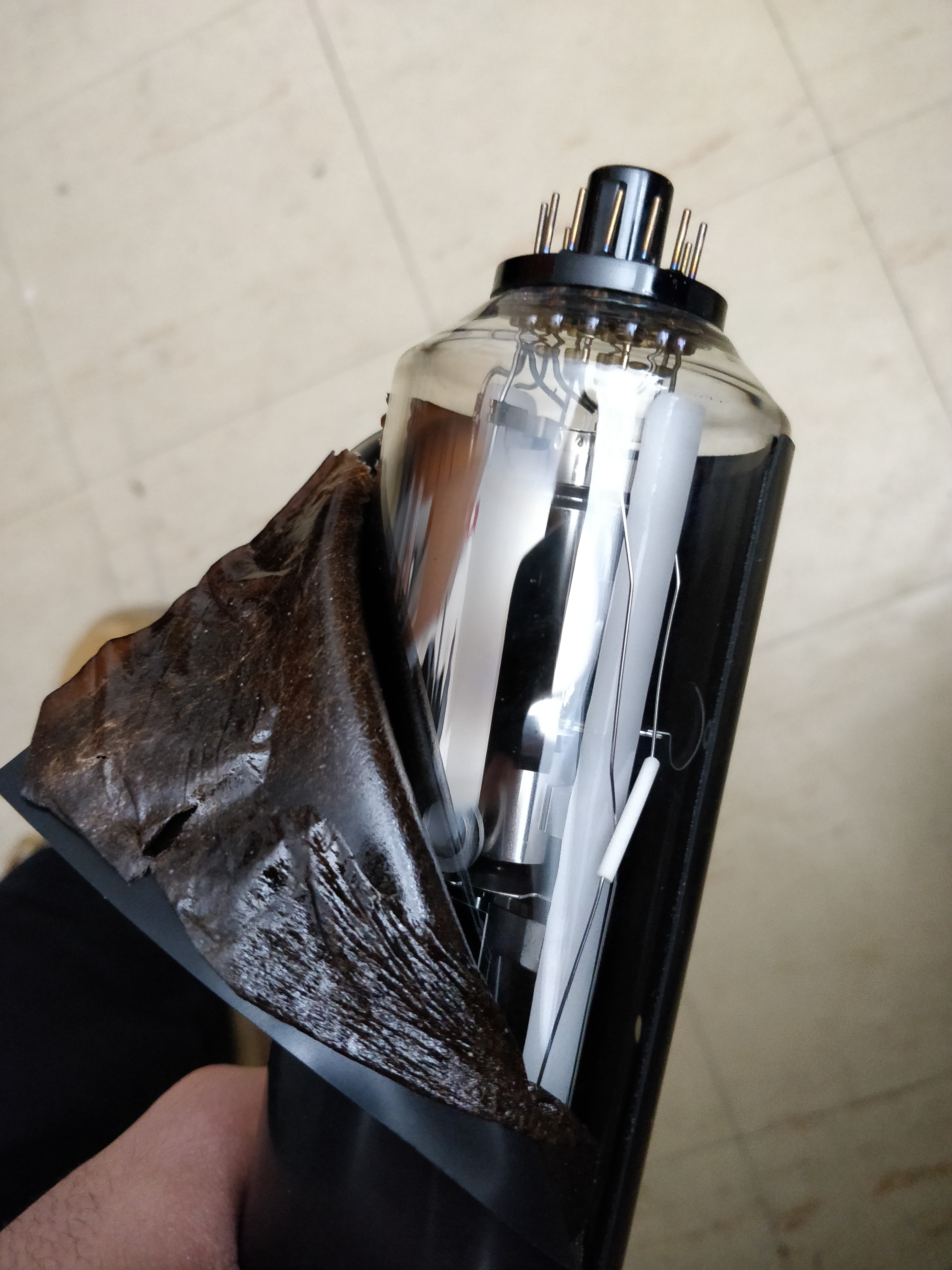
Getter flash looks good.
Shiny chrome/silver, no white at all. Inside components look good. No idea what this black insulation is, but I just quietly wrapped it back on.

Then this happened to the yoke coil (Or maybe it was like this already and I didn't catch it.)
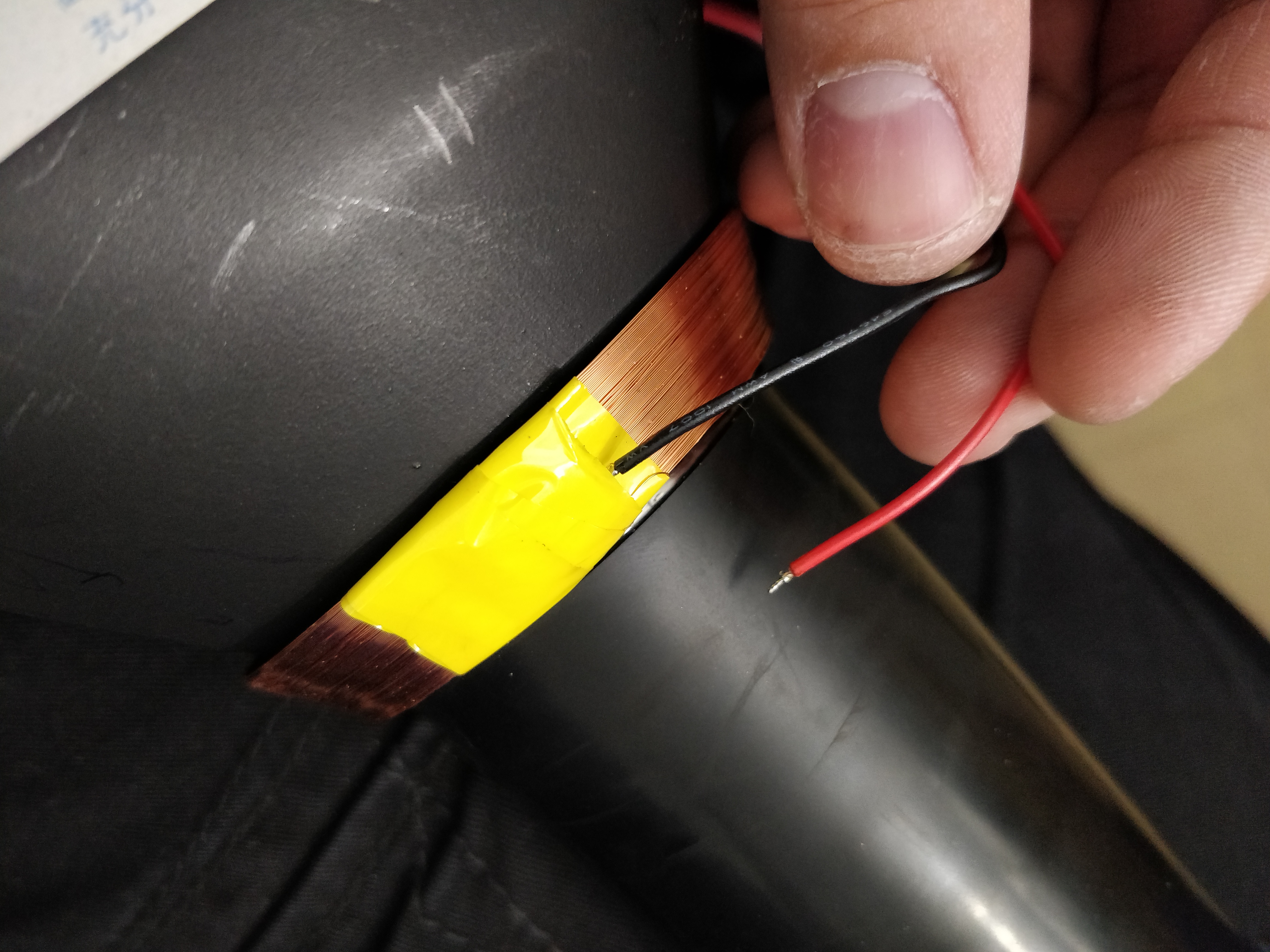

Fantastic.

I re-soldered the red wire back onto the small copper coil wire that was disconnected beneath the yellow insulation tape, but I had to slightly cut through the tape in order to get the wire out. Not sure what kind of tape this actually is. Trying to find some replacement tape.
I pushed the wires back under different layers of the tape (as they were before) so they don't make contact to anything else, or each other. Hopefully this doesn't disturb the deflection of the CRT.

After looking for cracks on the PCB's as some members have suggested, I found that after gently bending the high voltage/power supply PCB (PEF-999B in my case) that something was "creaking". One of the ground leads of the voltage multiplier (MUT1001) was loose. I re-soldered it, and it sits firmly again. I'm not entirely sure if this could have been a source of my problems, but hey why not? I'll keep checking for damaged traces/loose components.

Before I turned it back on to check the voltage rail points, I found something interesting:
The schematic for the HV board show a small PCB mount 400mA(?) fuse, F1001, on the +55V line that I didn't notice before. (Page 85 on the owner's manual. Thanks Chris56000!)
After checking it's continuity, it seems to be flat out dead.

Thing is, it's not an ordinary fuse but is a "Integrated circuit protector" (...So it's a fuse?)

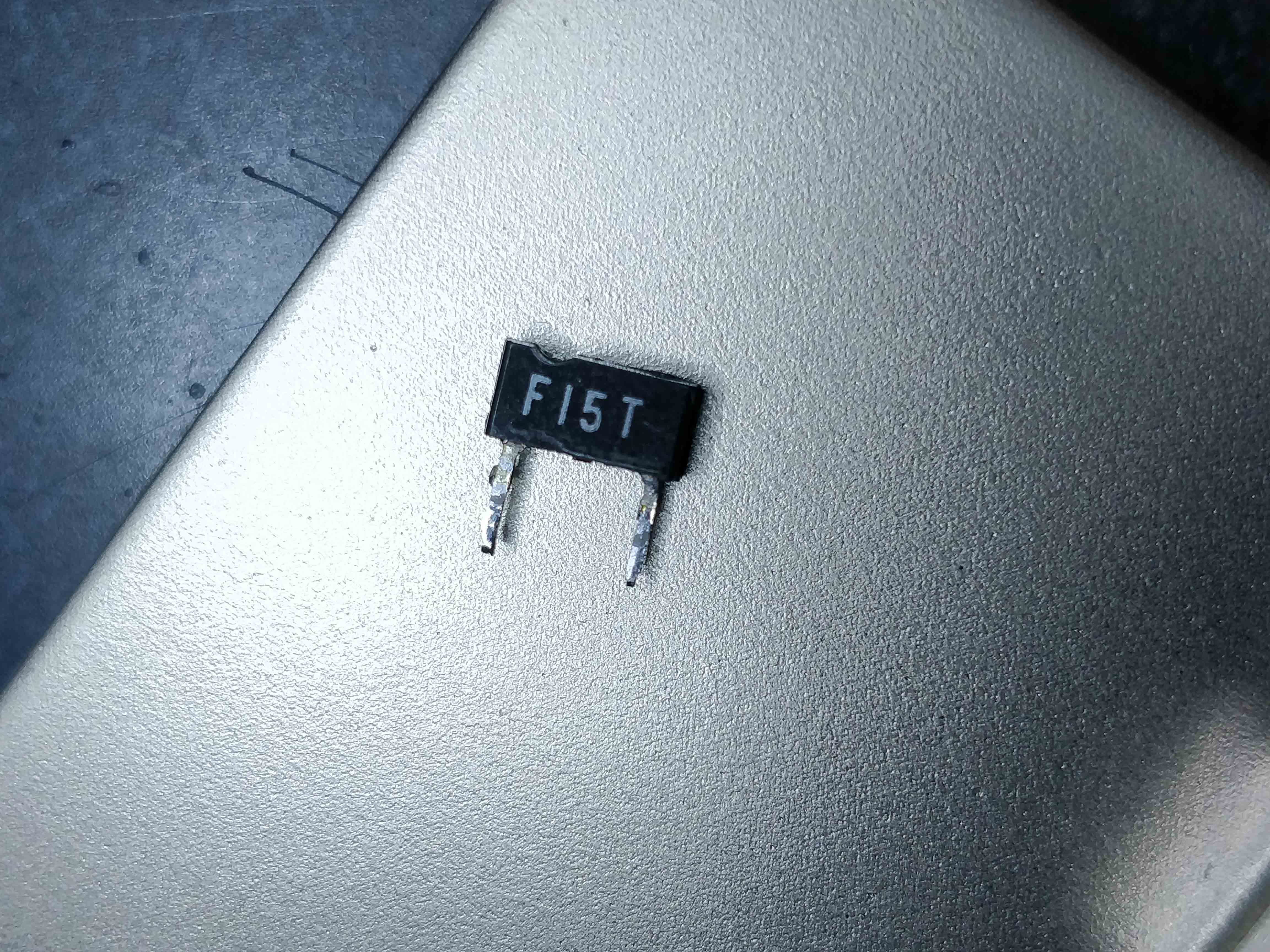
A bit of a bizarre fuse package I've never seen before.
From what I've found so far, it's an ICP-F15 from ROHM Co. The schematics show a wrong "ICP-F18" for some reason, and it's datasheet shows it as a 600mA fuse, not 400mA.
The datasheet is here.

What's bizarre is that this fuse is rated for 50V but regardless was placed on the 55V line? Not sure if 5V makes such a difference on a fuse.
I found replacement fuses on some sites I've never heard of. I'll try them out anyway.
But i'm worried that not too many of these fuses still exist, and if there's more problems on the board, the fuses might blow again when I attempt to test it.

Wondering what kind of an effect might occur if I temporarily run a cheaper, more easily available 500-600mA fuse with a higher internal resistance for testing?
ICP-F15's seem to only have an internal resistance of 0.135 Ohms. Neat?

Anyways, I have good hopes that the CRT tube itself should still be intact, and it leaves me to focus on searching for other problems on the PCBs. I might do something I keep seeing on this forum and recap the boards as well. Wouldn't hurt. I'll keep this updated when I can about my progress and whatever I find, for those interested. Any advice anyone shares is still always welcome!

Edit: I just realized I actually haven't worked on it/replied to this thread for more than just "4-5 months". Woosh. How did time fly by so fast!? My bad if i'm necroing this thread. Wow.
 
« Last Edit: July 05, 2018, 08:15:55 am by AbsoluteCatalyst »
 

Offline Gyro

  • Super Contributor
  • ***
  • Posts: 9506
  • Country: gb
Don't worry too much about that "yoke coil", it is the trace rotation coil (controlled by the trace rotate pot). It operates at low voltage, low current, DC so the odd shorted, or lost, turn (within reason) wouldn't be a disaster. It won't affect deflection. The tape is polyester (transformer tape) but not critical there.

Good news that the getter is still intact, I suppose there's still a small risk of bent deflection plates but that would be pessimistic. I think your current line of investigation will hopefully get you there.
« Last Edit: July 05, 2018, 08:48:22 am by Gyro »
Best Regards, Chris
 

Offline TERRA Operative

  • Super Contributor
  • ***
  • Posts: 2917
  • Country: jp
  • Voider of warranties
    • Near Far Media Youtube
If you are worried about that tape, some Kapton tape will be fine to use there.

For the fuse, any PCB mount fuse will do, as long as it has the appropriate current rating and equal or greater voltage rating.
Where does all this test equipment keep coming from?!?

https://www.youtube.com/NearFarMedia/
 

Offline Chris56000

  • Frequent Contributor
  • **
  • Posts: 903
  • Country: gb
Hi!

How come the chaps that unfortunately drop these things are in the USA or some other countries where going to help personally is out of the question for me?!

Pick up the oscilloscope and hold it VERY FIRMLY with both arms and hands, and move it from side to side and forwards and backwards, listening very carefully for any signs of rattling or anything moving about inside, in particular, any musical or metallic noises may point to physical damage to the CRT's electron gun!

If you do this and can hear nothing, refer to the manual and try the "beam finder" button to see the d any illumination of any sort can be seen on or in the CRT itself – if there is none, remove the case of the scope and view it in a darkened room to make sure the heaters are glowing, if they are not, it could be physical/electrical damage to the CRT itself, or almost any part of the circuitry!

I'm reluctant to give a detailed fault–finding guide as the OP may not be experienced enough to carry out investigation/repair in complete safety, and in my opinion, I feel the only way forward for the OP is, as other posters have said, put the damaged instrument to one side and obtain another one for testing/experimental purposes!

I understand the sentimental value of this instrument to the OP, and in this case, storing it to one side carefully until the OP is adequately skilled to repair it, or get skilled assistance from another Member, is the best way forward from here on!

Chris Williams


It's an enigma that's what it is!! This thing's not fixed because it doesn't want to be fixed!!
 

Offline Relayer

  • Contributor
  • Posts: 35
  • Country: au
Hello AbsoluteCatalyst,
If you have a variable DC power supply, you can check to see if the heater is
open circuit or not.
You only need to de-solder one pin on the neck board either side of the heater
and connect your power supply and slowly feed it until it glows. But DON'T exceed
4 volts. If it fails to glow, then the CRT is cactus.
If the tube is unserviceable, you might be able to pick one up from eBay, where
someone is selling the same model cro, but is faulty for a different reason.
Please let us know how you get on.
Regards,
Relayer
« Last Edit: July 05, 2018, 11:07:25 pm by Relayer »
 

Offline james_s

  • Super Contributor
  • ***
  • Posts: 21611
  • Country: us
Seems easier to check the heater for continuity with a multimeter than to risk damage by trying to power it.
 

Offline alsetalokin4017

  • Super Contributor
  • ***
  • Posts: 2055
  • Country: us
I'm guessing that the Beam Find button doesn't do anything.

Therefore the CRT and/or the HV supply are shot.
The easiest person to fool is yourself. -- Richard Feynman
 

Offline Cyberdragon

  • Super Contributor
  • ***
  • Posts: 2676
  • Country: us
He checked the filament along time ago and it seems to have continuity. He hasn't checked to see if it's actually getting power though.

Does it make any noise when powered on? (If it does that's good, if not it's ambiguos)
*BZZZZZZAAAAAP*
Voltamort strikes again!
Explodingus - someone who frequently causes accidental explosions
 

Offline AbsoluteCatalystTopic starter

  • Newbie
  • Posts: 6
  • Country: us
Only took a year.
« Reply #37 on: July 10, 2018, 02:02:30 am »


Well.

And the little Hitachi lived happily ever after.

Wasn't really expecting to repair it so fast since I just started working on it again.
All I've been doing since my last post on this thread was just waiting for the new fuse to arrive.
Once it was here I soldered it right into place, and what do you know?
It's alive. Perfect.

The blown pcb fuse is still a mystery to me, maybe a sudden surge due to the impact knocking other heavier components around.
Oh well.


Thanks for all the help and advice guys!


For anyone in the future that finds this thread and has a similar issue and has already done other things mentioned in this thread:

Check if your (HIGH VOLTAGE BE WARNED) voltage multiplier's leads are loose if you have one, by flexing the board or gently tugging on it checking for "slack". Mine had a slightly loose lead, and I resoldered it just in case.
Not entirely sure if this was the problem from the start, and it just caused my fuse to blow.


Check if your fuse (F1001) on the top power supply PCB is still functional (Check for working resistance/continuity) if it isn't, replace it with a new ICP-F15 or similar.
It runs on the 55V rail, which is why the buttons lit up, but the CRT didn't.
« Last Edit: July 10, 2018, 02:07:37 am by AbsoluteCatalyst »
 
The following users thanked this post: rbm

Offline james_s

  • Super Contributor
  • ***
  • Posts: 21611
  • Country: us
Did the fuse look blown? They can fail mechanically too, knocking it over could have just broken th element in the fuse.
 

Offline james_s

  • Super Contributor
  • ***
  • Posts: 21611
  • Country: us
Break it open and find out, a blown fuse isn't useful anyway. I'd say it's pretty likely the element inside simply broke mechanically, fuses are normally just a thin wire inside an insulating housing.
 

Offline Chris56000

  • Frequent Contributor
  • **
  • Posts: 903
  • Country: gb
Hi!

Well done on getting it going and I'm glad the CRT has survived - Japanese instrument CRTs are very well made and fairly robust!

ICP devices do tend to be both electrically and mechanically fragile, the F-type more so than the N-type, also overheating whilst soldering can make them go open-circuit.

I'd order a few ICP N-type of the same rating (they look like plastic-case transistors but only two leadout wires) - they will solder into the PCB same as the original device did.

Chris Williams

It's an enigma that's what it is!! This thing's not fixed because it doesn't want to be fixed!!
 

Offline rbm

  • Regular Contributor
  • *
  • Posts: 230
  • Country: ca
Re: Only took a year.
« Reply #41 on: July 11, 2018, 06:24:32 pm »
For anyone in the future that finds this thread and has a similar issue and has already done other things mentioned in this thread: ...
Thanks AC!  I've saved the information in my archives.  I have a Hitachi V695 which is very similar to the V1565.
- Robert
 

Offline padee

  • Newbie
  • Posts: 1
  • Country: ie
Re: Toppled over my analog oscilloscope. Now no display. (Hitachi V-1565)
« Reply #42 on: August 01, 2020, 07:33:38 am »
Thanks OP for taking the time to add this post to it's conclusion. I purchased a presumed good v1565 and was refunded when found to be not working. After reading this thread I tested that fuse and got very excited about replacing it! Sure enough I now have a working scope for the price of a fuse :-+   
 
The following users thanked this post: Ian.M


Share me

Digg  Facebook  SlashDot  Delicious  Technorati  Twitter  Google  Yahoo
Smf