Author Topic: Volvo electronic module repair.  (Read 33910 times)

0 Members and 1 Guest are viewing this topic.

Offline juris.dTopic starter

  • Contributor
  • Posts: 15
Volvo electronic module repair.
« on: April 06, 2015, 06:38:44 pm »
Hello all!

Long time watcher, first time poster who finally needs to ask for your help/advice. I am warning you in advance, that I am a newbie who knows the basic theory and enjoys watching a lot of youtube videos of Mike, Dave, AvE, Jerri Elsworth, Applied science and so on, however, I am not by far an electronics engineer.

I have an automotive repair dilemma here which ultimately boils down to electronic fundamentals in repairing a water damaged device that processes CAN signals.

INTRO start
skip this if you are not interested in the explanations
I own a volvo s80 (2003) that has stood on the outside for some time and it has turned out, that it has the infamous sunroof drain problem which in turn has caused water damage to the Central Electronic Module of the car. If anybody is interested in more details, please ask, but I arrived to this conclusion after a few basic fixes of the failed window washer pump did not work... And after taking out the module itself, you can see the substantial damage caused to it.

The repair at the dealer costs too much for me to consider this option - 1000 EUR for the module plus another approx. 200 EUR for adding it to the car as they apparently have unique identifiers and the ECU will not recognize it, thus it will not work (there is some blabber about downloads from Volvo servers within the VADIS (volvo's own diagnostic software) package which you need to have a subscription etc.) All of that being done to prevent these modules from being stolen and sold left and right.

I have googled quite a lot and it seems that these modules are easily repairable, and a few people have completed it, but with different main causes. As well as there are services that specialize in the repair of these devices.
INTRO end

This leads me to believe, that I can attempt a DIY fix for it. I have a donor device, but I am not sure of the internals as I haven't had the time to pry it open and see if they are similar internally.

The more interesting and detailed explanation can be found here:
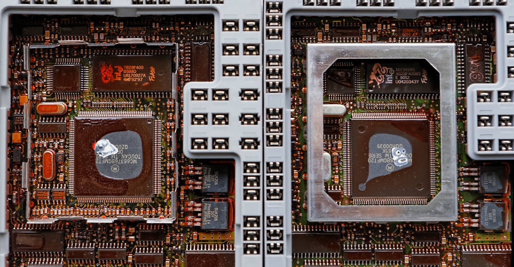
http://lag.lt/repairing-volvo-cem/
A Lithuanian guy (I am Latvian) has replaced the MCU from a donor device in to his old device and it has worked.

A picture of the old and new devices from the blog for those who do not surf links:


Due to the fact that my CEM module is badly damaged, I do not think that a lot of the components will be usable as the water has corroded a lot of pins which have come out, as well as surely corroded much more.
This leaves me with the option, that is being stipulated in the blog above:
"read flash from dead CEM; re-program new replacement CEM, done."

in your, experienced opinion - is this a feasible option? would it be possible with simple tools to pull the the data from the flash (I assume this is what stores the ID and other config data that is being transmitted to the ECU so that it gets recognized/becomes compatible) or is there a caveat that neither the author of the idea, nor me do not see? (something along the lines of the fake FTDI chips and them being broken if you use official software?).

why does the author say, that he has tried swapping the flash chips around and it did not work? due to different hardware layouts maybe?

As well, I assume that the replacement/donor module, that I have acquired, has to be 1:1 to be compatible with the car itself (i do not expect an answer to this).

Please see a gallery of the water damage to my module below:

http://imgur.com/a/wGSNf

I would really appreciate any input in this as going down the expensive route is not really something I want.

Thanks,
Juris.
 

Offline McBryce

  • Super Contributor
  • ***
  • Posts: 2682
  • Country: de
Re: Volvo electronic module repair.
« Reply #1 on: April 06, 2015, 09:21:05 pm »
Hi juris,
     how much soldering experience do you have? Unless you are very well experienced, this isn't a solder job I'd recommend a beginner to attempt. Also, do you own the equipment to do the job? If it means buying a hot-air station, programmer, new chip etc. then it's going to cost quite a bit to do anyway.

Can you post some pictures of your device so that we can assess the damage?

McBryce.
30 Years making cars more difficult to repair.
 

Offline juris.dTopic starter

  • Contributor
  • Posts: 15
Re: Volvo electronic module repair.
« Reply #2 on: April 06, 2015, 09:40:17 pm »
Thanks for your reply, McBryce, but it seems to me that repairing the device itself is too costly compared to the fact that they are easily copy-able, even though bound to the car.

Some extent of the damage can be seen on the pictures in the bottom gallery - more the connectors then the board itself, but, ahh, well.

I have done a fair bit of reading in multiple languages on this, and apparently the water damage, as well as over-heating of the MCU is a very common problem. There is even a service of copying the data over to a refurbished device. http://xemodex.com/us/product/central-electronic-module-program-transfer-for-volvo-vo-1070-30657629-00-22/

I bought my donor for 15EUR.

Now, my question is, how to transfer the data from one to another, or rather, whether I should bother with a JTAG with copying the processor config data and copying the flash, or just copying the flash alone will suffice.

I have read on forums that people have copied the config from the flash numerous times and that should be enough. Apparently the intel 28F400 chip is the one of importance and it has been mentioned in a multitude of posts in the russian speaking part of the internet.

If this is so easily done (apart from some caveats that they lose the configs, knock on wood), I would like to find out how I can do it myself.

only thing i am puzzled by is - why copying the flash helps, but re-soldering the chip from one board t another - does not (and this is my extent of knowledge, maybe it is just fundamentals).

To answer your question - I am not intending to do it myself, but rather take it to a friend who has the equipment and skills and he can assist me, yet I cannot bother him with doing all of the research for me. My soldering skills are adequate to deal with this task to the level I am happy with. not much more then that :)

thanks for the answers in advance!
 

Offline Zepnat

  • Regular Contributor
  • *
  • Posts: 84
  • Country: gb
Re: Volvo electronic module repair.
« Reply #3 on: April 06, 2015, 10:16:36 pm »
If it was mine I think there'd be more chance of me repairing the broken pins than swapping chips around there only seems to be a couple broken and a bit of corrosion the circuit board looks heavily coated and should be ok ?
 

Offline Evil Lurker

  • Regular Contributor
  • *
  • Posts: 67
Re: Volvo electronic module repair.
« Reply #4 on: April 06, 2015, 10:58:13 pm »
Mostly what I see is a bunch of galvanic corrosion on the connectors. The board itself may be OK as it is covered in a conformal coating.
 

Offline amyk

  • Super Contributor
  • ***
  • Posts: 8258
Re: Volvo electronic module repair.
« Reply #5 on: April 07, 2015, 12:35:35 am »
The MCU there is a MC68376BGMFT20, which does not contain any flash memory of its own. (Apparently it's been replaced by the SC68376BGMAB20, a drop-in replacement that costs around $30 each...) There's a mask ROM option, so buying a blank MCU to replace it might not work, but it also means that all the data necessary to customise it to a particular car will be in the flash.
 

Offline McBryce

  • Super Contributor
  • ***
  • Posts: 2682
  • Country: de
Re: Volvo electronic module repair.
« Reply #6 on: April 07, 2015, 10:55:32 am »
After seeing the pictures, I also think that cleaning and/or replacing the pins should be enough to get it back working. It's definitely what I'd do first before I'd consider any chip swapping or flash reading.

McBryce.
30 Years making cars more difficult to repair.
 

Offline juris.dTopic starter

  • Contributor
  • Posts: 15
Re: Volvo electronic module repair.
« Reply #7 on: April 07, 2015, 12:10:10 pm »
If one has the tools and a replacement - isn't dumping the flash from the old one and flashing it in to the new one the quicker and financially more viable option considering that all of the tools are there?

I am not certain as to how to connect to the 44pin flash device, but I have read in the russian forums that you do not need to de-solder it to be able to manipulate with it. there are SIOC8 clips out there for programmers, is there nothing similar for 44pin devices? people have even called others stupid for removing the flash chips as apparently it should be like a superbly easy fix - copying the contents over...

the current status is -
1) two pins are completely gone - they remained in the connector when pulling it out. When trying to poke it with a needle, one of them fell completely apart;
2) two pins are broken halfway down the middle;

I appreciate that it is only 4 pins that actually need repairing, but I am more concerned to the extent of the damage, even though the board is conformally coated, does the corrosion not find its way in to the layers of the board?

I have heard horror stories of the CAN network disappearing completely due to water damage (resistance changes). Even though I have read the fault codes with DICE from the particular device.
 

Offline ABL

  • Newbie
  • Posts: 2
Re: Volvo electronic module repair.
« Reply #8 on: April 07, 2015, 07:02:52 pm »
    Hi,
    long time reader, first time poster.
    Writing only because i repaired CEM once... In fact, that photo in first post is mine :P
    Not sure if it helps, but...:
    • I would not bother with resoldering MCU and so on. In your case - first fix all contacts (clean up, crimp endings (you can do that with pliers, no need for special tools), wash with isopropyl alcohol, or toothbrush+brake cleaning fluid...)
    • if this does not help (check with DICE if you have access to it - is anything visible behind CEM, like AUM, rear electroncs module, ETM and so on?) - pick magnifying glass and check pins near connectors (check for corroded solder, looks a bit similar to cold soldering). If you find anything similar - just put lots of flux and reflow solder around with soldering iron (or even hot air gun if you have one)
  • My issue is a bit different from yours. On older Volvos MCU's died due to heat (hot climate, poor cooling - dead after few years), usually it shows up as "lost link to some module on network". Just getting water on CEM should not damage anything, as it's coated with thick layers of conformal coating. So, i really doubt that swapping MCU would fix issue.
Also - i swapped just intel chips - another module won't work (probably because it's slightly different). So, as i wrote - "probably" reflashing content would help, but i would not try to do that if i had similar module nearby. Both IC's are hard to access (they both are in metal box, which should be cut/removed to unsolder them), so unsoldering Intel EEPROM, reflashing, re-soldering => probably more work than just "remove dead MCU, put new, done".

Relays which are here can be damaged with water (they aren't waterproof and contacts aren't coated), so, as i said - first step - clean up everything and connect pins back (this is really easy task). Then write symptoms...
 

Offline marshallh

  • Supporter
  • ****
  • Posts: 1462
  • Country: us
    • retroactive
Re: Volvo electronic module repair.
« Reply #9 on: April 08, 2015, 03:12:01 am »
IIRC there were a couple places that would do CEM rebuilds (Xemodex?)

It seems you should first start repairing the damage around the CEM including the wires and connectors, then repairing the CEM connectors. Then once you're sure of a good connection, test to see if it's really necessary to rebuild the CEM.
« Last Edit: April 08, 2015, 03:15:10 am by marshallh »
Verilog tips
BGA soldering intro

11:37 <@ktemkin> c4757p: marshall has transcended communications media
11:37 <@ktemkin> He speaks protocols directly.
 

Offline juris.dTopic starter

  • Contributor
  • Posts: 15
Re: Volvo electronic module repair.
« Reply #10 on: April 08, 2015, 11:11:47 am »
if this does not help (check with DICE if you have access to it - is anything visible behind CEM, like AUM, rear electroncs module, ETM and so on?)

the only module that is not visible during a DICE scan is the Upper Electronic Module (the rear view mirror), which controls the remote, the dome lights and the sunroof. unfortunately, it does not work itself either.

There are a multitude of causes to the UEM not working (break in attempts, dead battery in the siren that locks the module out, no power etc.)

After studying the wiring diagrams for the CEM, I have found that the power to the UEM goes through the CEM and since the investigation, there are currently 4 pins broken and the only other thing in the car that drops an error, apart from the windscreen washer, is the front driver's seatbelt buckle (SRS airbag error).

this leaves me with 2 pins, since the seatbelt buckle has just 1 sense pin going to the CEM. So I am trying to hope and assume that after the repair/replacement, there should be power to the UEM.

As for marsallh's post:
The car is located in Latvia, xemodex is an American (i believe) institution and it would cost me much more than the 1k EUR to get the module to them for a rebuild. Having said that, there is an english service out there as well that does a rebuild, but it does not have any reputation out there, though...

The wires have been repaired already, they all are standard connectors you can pull out of a PC (i have loads of those in my scrap boxes).
 

Offline juris.dTopic starter

  • Contributor
  • Posts: 15
Re: Volvo electronic module repair.
« Reply #11 on: April 30, 2015, 07:36:32 pm »
I am going to revive this topic a little bit and maybe somebody can help me as I have run in to a problem.

Took the module to an acquaintance of mine who decided that for him it would be easier to take the flash off, read it, take the flash off the donor device, erase it, flash the contents of the original one in to the donor device, solder it back on and we should be good to go.

well, at least that was the plan.

Please see the gallery here:
http://imgur.com/a/wHhLr

first of all, the flash chips are different:

1) the original has an Intel 28f400
2) the donor has a Micron (MT) 28f400

Now, we encountered an unusual problem with the reader. The reader is an official MiniPro TL866 with an official TSOP44 V.3 adapter. The adapter has been tested previously on other projects and working.

The reader does not read the Intel chip properly. Every time it reads the chip, it generates a different checksum and it is not possible to write it to the Micron chip as it drops an error.

Currently we are puzzled as to what the cause could be, but I have googled myself numb and haven't become any wiser.

There is a google link to this forum where in the topic discussing the TL866 somebody has said that the adapter is not the right one for reading 28F400 chips. I am not certain how to distinguish as the pictures are very scarce.

This forum linked at the bottom states that one should read and validate each section one by one and only then it can be summarized properly.
http://www.thirdgen.org/forums/diy-prom/452800-possible-read-intel-28f400bx.html#post3592927

Can anybody comment on this? Any advice would be appreciated.

If there is no quick way of fixing this would it be possible to solder the intel flash in to the donor device? I know that ABL stated in his link that he has tested this and it has not worked for him (http://lag.lt/repairing-volvo-cem/) but I somehow do not seem to comprehend what could affect it. I have read on another lithuanian site (codecard.lt) that if somebody is fiddling around with that particular chip, it is highly suggested to replace the chip with a new one, as they tend to fail occiasionaly. So, theoretically, if one puts a completely new chip in, there shouldn't be anything to restrict this from happening...

What is the 44pin device on the left of the flash chip and would it make any difference if we transfer it along with the flash? We have figured out that it contains an EPROM and it might contain something of significance...

Any input would be appreciated.

P.S. on the russian internets everyone suggests that this should be a fairly easy operation and a common fix for these CEM modules - copying the contents of the flash chip over to the donor one and apparently everyone and their dog does that (granted they have equipment).

P.P.S. The damage around the CEM has been repaired and the connector is as good as new.
 

Offline pinyoro

  • Contributor
  • Posts: 30
Re: Volvo electronic module repair.
« Reply #12 on: April 30, 2015, 08:22:47 pm »
I am unsure if this is allowed to direct you to another website but here goes.. visit www.digital-kaos.co.uk . There are forum pages that deal with cloning engine ECU'S and ECM'S.  There is a wealth of knowledge there and a lot of knowledgeable people in this field. You'll have to register first.
 

Offline pinyoro

  • Contributor
  • Posts: 30
Re: Volvo electronic module repair.
« Reply #13 on: May 01, 2015, 12:45:37 am »
With ECM'S if you replace the flash this is usually not sufficient for the car to start. The flash usually contains the program which the microntroller runs. Quite often there will be an eeprom which contains data specific to the vehicle including immobiliser data. When you insert a key into the ignition the immobiliser box will communicate with the ECM via the CAN bus if a valid key is inserted. The command to allow the ECM to start the car amongst other things will only occur if the data in the ECM corresponds with the data in the immobiliser.
 

Offline juris.dTopic starter

  • Contributor
  • Posts: 15
Re: Volvo electronic module repair.
« Reply #14 on: May 01, 2015, 09:15:52 am »
With ECM'S if you replace the flash this is usually not sufficient for the car to start. The flash usually contains the program which the microntroller runs. Quite often there will be an eeprom which contains data specific to the vehicle including immobiliser data.

what you are saying makes not much sense, especially, because you clearly haven't read the whole thread. in particular this.

The MCU there is a MC68376BGMFT20, which does not contain any flash memory of its own. (Apparently it's been replaced by the SC68376BGMAB20, a drop-in replacement that costs around $30 each...) There's a mask ROM option, so buying a blank MCU to replace it might not work, but it also means that all the data necessary to customize it to a particular car will be in the flash.

so, taking this forward - if copying the contents of the flash works why soldering in a flash chip from another device does not work? (the only thing i can think of is SW incompatibility, but then again, copying the contents would not work either).
 

Online nctnico

  • Super Contributor
  • ***
  • Posts: 26875
  • Country: nl
    • NCT Developments
Re: Volvo electronic module repair.
« Reply #15 on: May 01, 2015, 11:25:12 am »
I looked at the pictures but I strongly suggest to swap the connector from the donor to the original and fix or replace the connector on the wiring harness. Trying to copy data or swap chips is way more work with an uncertain outcome. I have the tools and skill to swap the memory chip but I would not go that route.

Like others said: the PCB is covered in conformal coating and won't be affected by the water.
There are small lies, big lies and then there is what is on the screen of your oscilloscope.
 

Offline juris.dTopic starter

  • Contributor
  • Posts: 15
Re: Volvo electronic module repair.
« Reply #16 on: May 01, 2015, 11:44:55 am »
Trying to copy data or swap chips is way more work with an uncertain outcome. I have the tools and skill to swap the memory chip but I would not go that route.

Like others said: the PCB is covered in conformal coating and won't be affected by the water.

the chips are out already, hence having the issue with reading the intel one.
http://imgur.com/a/wHhLr

as a result, I want to know if I can solder the intel chip in to the space where the micron used to be, or will it cause any issues?

or are you suggesting to solder the intel back in to the place and start working on the connector?
 

Online nctnico

  • Super Contributor
  • ***
  • Posts: 26875
  • Country: nl
    • NCT Developments
Re: Volvo electronic module repair.
« Reply #17 on: May 01, 2015, 12:45:27 pm »
I'd solder the Intel back in and swap the connector. Much less work.
There are small lies, big lies and then there is what is on the screen of your oscilloscope.
 

Offline juris.dTopic starter

  • Contributor
  • Posts: 15
Re: Volvo electronic module repair.
« Reply #18 on: May 01, 2015, 12:59:11 pm »
The micron is out as well, so, work wise, it would be more work to put the intel back and start work on the connector compared to putting the intel in to the space where the micron used to be as the donor is completely intact.

Are you still suggesting to put the intel back where it used to be?

Are you in a position to answer whether theoretically it would be possible to put the intel where the micron used to be?

thanks.
 

Online nctnico

  • Super Contributor
  • ***
  • Posts: 26875
  • Country: nl
    • NCT Developments
Re: Volvo electronic module repair.
« Reply #19 on: May 01, 2015, 01:58:32 pm »
Based on the part numbers I think they can be exchanged. If both ECUs are exactly the same I think there is a chance it can work. The big IF is whether the numbers which marry the ECU to the rest of the car are inside the flash chip or not.

IMHO changing the connector is a path with less chances of things going wrong (if you have good desoldering braid and a good iron).

Edit: the webpage you linked to seems to suggest just swapping the flash is not enough to get a different ECU to work in your car.
« Last Edit: May 01, 2015, 02:06:44 pm by nctnico »
There are small lies, big lies and then there is what is on the screen of your oscilloscope.
 

Offline juris.dTopic starter

  • Contributor
  • Posts: 15
Re: Volvo electronic module repair.
« Reply #20 on: May 01, 2015, 02:47:39 pm »
The big IF is whether the numbers which marry the ECU to the rest of the car are inside the flash chip or not.

Edit: the webpage you linked to seems to suggest just swapping the flash is not enough to get a different ECU to work in your car.

The numbers that marry the CEM to the ECU are stored in the flash. that is a proven fact and as I have said, usually what people do (well, in post soviet countries anyway) is - they copy the flash contents from the broken module to the new one and everyone suggests that being the best option.

I raised this question exactly because the webpage suggests it did not work but I am trying to comprehend - why? if all the data is stored in the flash as well as technically the parts are the same just from a different supplier I do not see why it should not work...
« Last Edit: May 01, 2015, 02:49:22 pm by juris.d »
 

Offline amyk

  • Super Contributor
  • ***
  • Posts: 8258
Re: Volvo electronic module repair.
« Reply #21 on: May 01, 2015, 03:04:58 pm »
The reader does not read the Intel chip properly. Every time it reads the chip, it generates a different checksum
I suspect it could be reading the chip too fast, or you have an intermittent connection. Read several times, and diff the resulting binary files, see what bytes differ between them. Apply pressure to the connector, see if that changes anything. If your programmer supports choosing a different read speed, turn it down.

Not all 28F400 are the same. Your Intel one in particular appears to be an AB28F400B5B80, which is an 80ns, 5V version with bottom boot blocks. I can't see the part number of the Micron one exactly but if they differ slightly it could explain why transferring it over directly to a different module won't work but copying the software does - there may be jumpers on the board to configure the MCU to the flash type. You'll need to read and compare the datasheets.

Quote
What is the 44pin device on the left of the flash chip and would it make any difference if we transfer it along with the flash? We have figured out that it contains an EPROM and it might contain something of significance...
Part number?
 

Offline juris.dTopic starter

  • Contributor
  • Posts: 15
Re: Volvo electronic module repair.
« Reply #22 on: May 01, 2015, 04:12:38 pm »
oh wow, amyk! i bow to you.

This is one of the first posts that actually answers my question. Gives something to think about.

As for the micron - on the top line it just says MT 28F400B5(6?) and on the bottom line, SG-8 BET and there is another letter there which I cannot make out.

Looking at this description here:
http://www.digchip.com/datasheets/quote.php?action=search&pn=MT-28F400B5

MT28F400B5SG-8 BET and MT28F400B5SG-8 BET TR look to be 80NS as well.

As for the 44pin device, I will check in the evening and let you know.

Thanks a lot!
 

Offline juris.dTopic starter

  • Contributor
  • Posts: 15
Re: Volvo electronic module repair.
« Reply #23 on: May 07, 2015, 11:19:57 pm »
I will bump this topic again.

After extensive datasheet surfing we have decided to solder the Intel in to the space where the Micron was.

why, as discussed, it is compatible with the intel in all ways.

I will try to decode the product data for a google bot future reference with this little cheat-sheet.

Intel.


Micron.


So, the Intel, as discussed is an AB28F400B5B80 which, if translated roughly, is an:
Automotive (A) 44-lead PSOP (B) Intel flash (28F) x8/x16 selectable 4mbit (400) Boot Block (B) 5 Volt (5) Bottom Boot (B) 80ns access time (80) module.

In turn, the micron is a MT28F400B5SG-8 BET F, again, translating this it would mean, that it is a:
Micron (MT) flash (28F) x8/x16 selectable 4mbit (400) Boot Block (B) 5 Volt (5) 44pin PSOP (SG) 80ns access time (-8) Bottom Boot (B) extended temperature (ET) module.

I have found no reference to the F, though.

I assume that the Automotive range in intel is something similar to the extended temperature range in the Micron.

As a result, one can clearly see (thanks to Amyk) that they are compatible and theoretically should work. I will post an update later in the afternoon.

I guess that this is just plain basics of electronics and reading and interpreting the part numbers, but, well, one has to learn all the time.

To answer my question as to why the lithuanian colleague's (ABL) flash swap operation did not work, if you look closer at the picture you can distinguish the differences in part numbers:
http://lag.lt/screens/misc/cem_both.jpg

The flash memories both are intel, but one is a TB28F400B5B80 and the other one is a AB28F400B5E5012

The TB and AB do not matter much as they are just the application designators - TB for extended temperature PSOP44 and AB for automotive PSOP44, but the red bit is fairly important.

As far as I can decode, the latter is a 50ns access time module, but I haven't found any reference as to what the E and 12 stand for.

Anyone care to comment?

As a result, the two are clearly not compatible due to the access time limitation and the E designator (low voltage maybe?) as well as the following digit - 12.

The relevant datasheets:
ftp://download.intel.com/design/archives/flash/docs/29215404.pdf
http://download.intel.com/design/archives/flash/docs/29053006.pdf
http://download.intel.com/design/archives/flash/docs/29050101.pdf
https://www.micron.com/~/media/documents/products/data-sheet/nor-flash/mt28f004b5.pdf

As for the controller, Amyk, it is a certain AS82527 - Intel serial communications controller.
 

Offline ABL

  • Newbie
  • Posts: 2
Re: Volvo electronic module repair.
« Reply #24 on: May 15, 2015, 06:26:48 am »
I do not see why it should not work...
Different board?
For example, in my pic: http://goo.gl/jxBtdk - boards are different (ignoring metal case - look into left side of board, outside of shielding).
Even very small differences between boards may require different software versions (with minimum requirement on them).

Did you tried to swap MCU?


Share me

Digg  Facebook  SlashDot  Delicious  Technorati  Twitter  Google  Yahoo
Smf