With everybody posting up atten PS tear-downs, I figured I'd post up my findings/mods to this power supply. I think you have to buy these supply's with the knowledge that they do have issues and it's a project rather than a perfect product out of the box. Theres 2 versions of this power supply, old and new. The old ones have hot glue instead of yellow adhesive over all of the connectors, a hand wound current shunt wire, metal wire jumpers instead of 0 ohm resistors. The new has the aforementioned yellow adhesive, and a mechanically wound current shunt wire (more on this later).
The first mod to this PS was to cut out the stamped metal fan guard and replace it with a proper chrome wire guard (PC) this increases airflow quite a bit in general. Second the very loud "Runda" "good quality fan"(printed right on it! lol) was replaced with a silent Enermax fan.
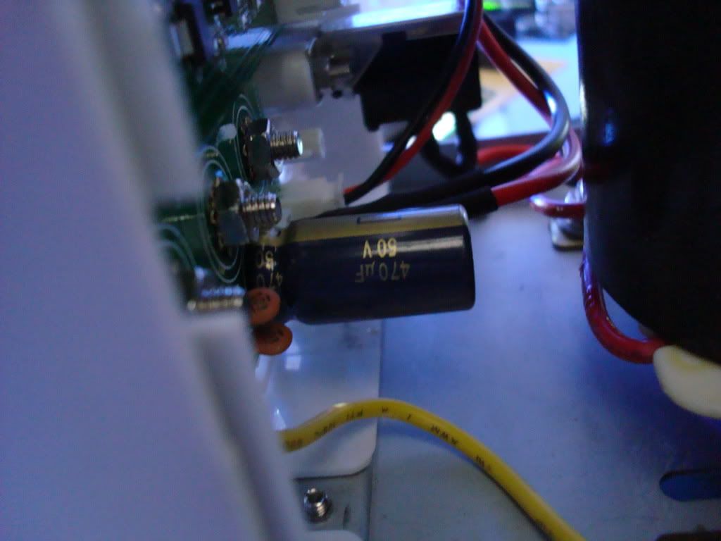
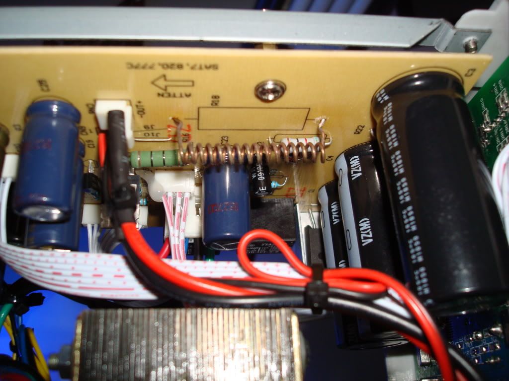
The second mod was more involved, I recapped all of the large electrolytic caps with name brands. The three large input caps (after the rectifier) were originally 2200uf @63v they were replaced with 4700uf@63v Nichicon caps. All of the others were replaced with the same value Panasonic FM and FC series caps.
I did the crystal mod from 8.00 to 16.00 Mhz as Bobski pioneered, unfortunately on this board it appears that atten has set the reset disable fuse, therefore I am unable to reprogram it.
As Miti pointed out the bridge rectifier gets worryingly warm with nothing more than a dinky heat sink to keep it cool. I de-soldered it and relocated to the chassis as seen in a number of mastec PS's. Problem solved, barely gets warm.
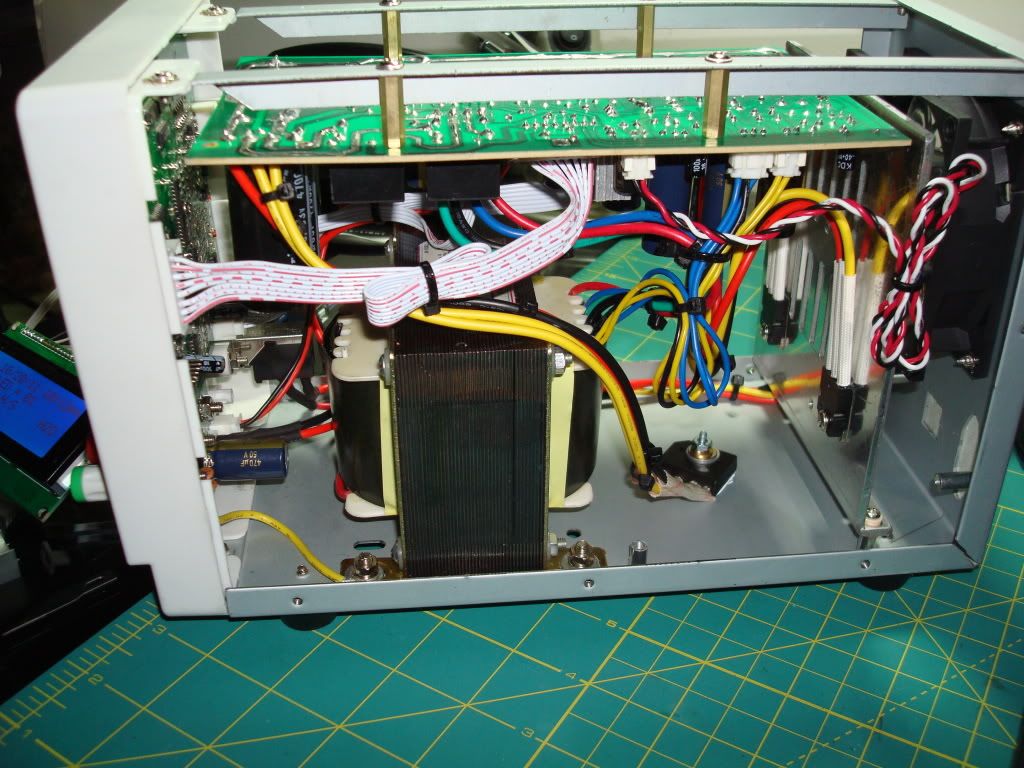
Also I think Bobski's issue with slow current limiting and slow/no updating of the voltage during CC mode stems from the current shunt wire, My supply showed the same behavior as bobski's with the hand wound shunt in place, when i replaced it with the newer machine wound shunt it updated the V display and switched to CC very quickly. Don't ask me why this works, it just did for me YMMV.
I plan on integrating the pc control part of this supply in the future, I was able to track down the software, all I have to do is build the usb bridge with an FTDI chip.
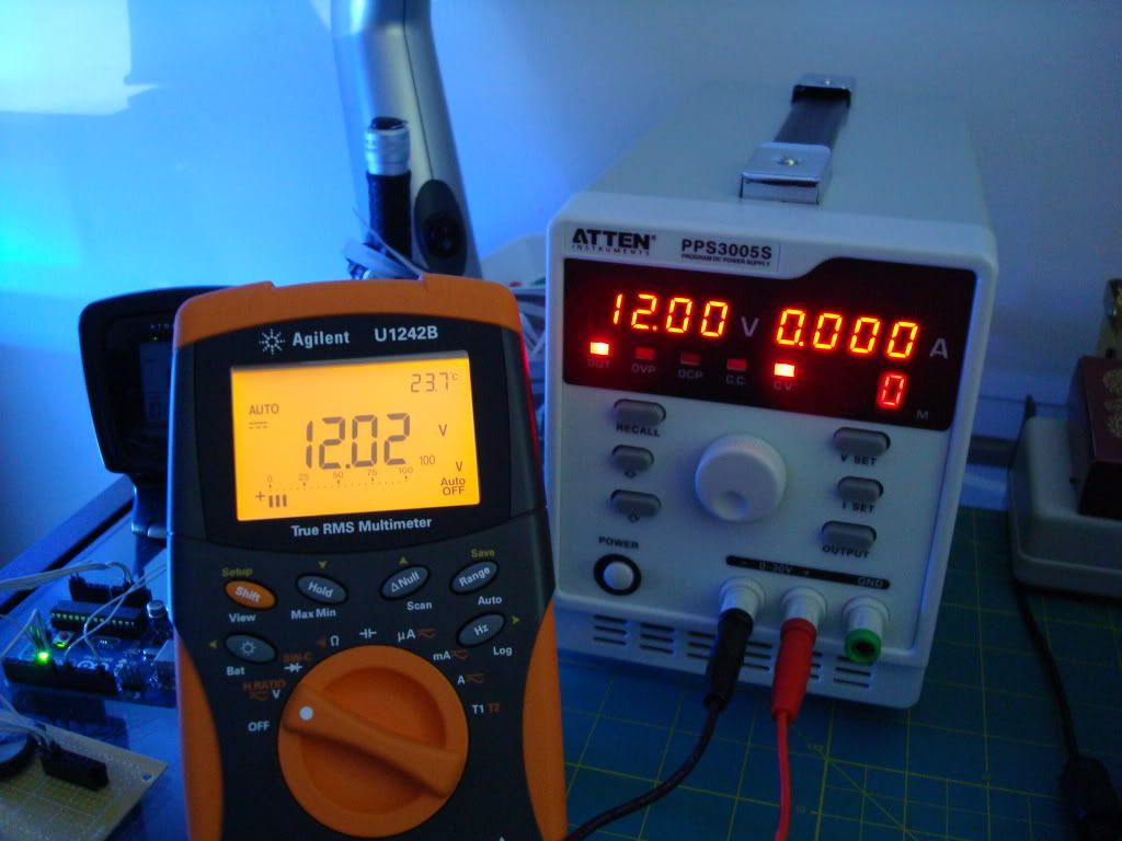
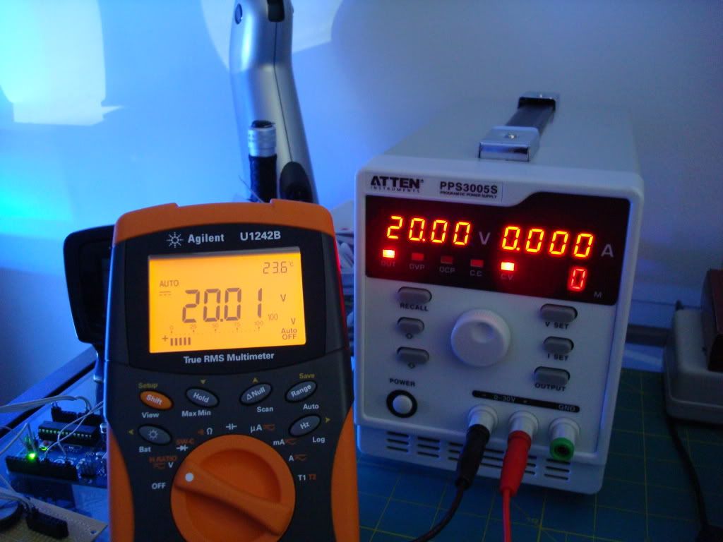
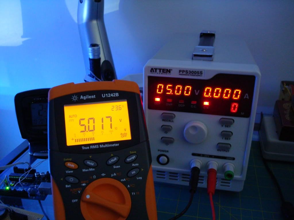
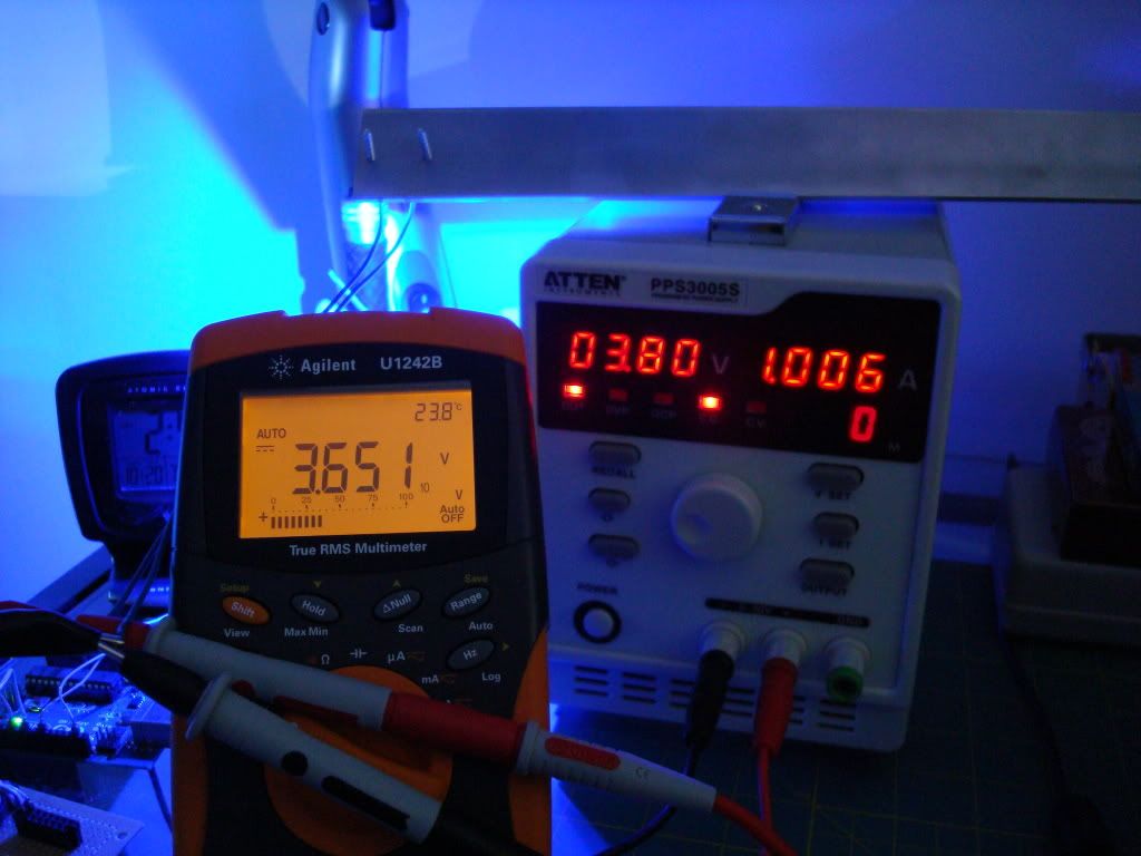
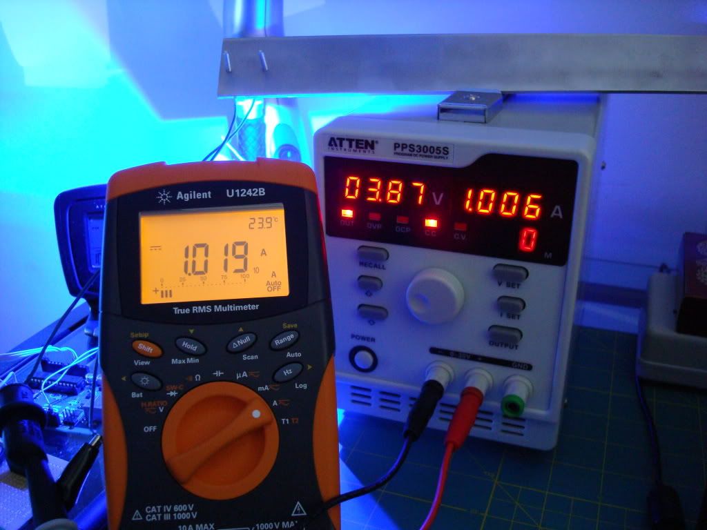
I did some tests to see about accuracy. The load was a 3w cree attached to aluminum angle run at 1A