Here's an interesting one that I've been sitting on for a while, got a unit being sold "for parts". It's a compact aircraft altimeter from the 70's, which I figured would be more interesting to look at vs. a more predictable-on-the-inside modern altimeter (as sending and receiving Ghz signals is no big deal now, but was much more difficult and cutting-edge then). Aircraft altimeters typically operate at 4.2-4.4 Ghz, from what I could find.
It's a small self-contained unit which consumes ~7W of DC power, and has a connector with 4 pins: two are for power, and the other two likely go to either side of an indicator, judging by the other Bonzer altimeter pinouts from the same era.


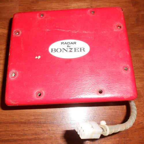
Let's take a look inside...
There's two boards on either side of a horn antenna.

One of them is marked "TR board" (probably "Transmit/Receive")...


...and the other is marked "PS board" (probably "Power Supply"):

The external connector wires come directly into a terminal strip, where everything gets RF suppression caps to the frame ground:

Taking off the red cover on the bottom/outside, we can also see the E-field "probe" inside the horn antenna, which performs the transition between the antenna and whatever's in that fascinating brass "T" on the TR board:
 RF Section
I unscrewed the "probe" with a wrench, and this released the brass section, which I could now look inside:

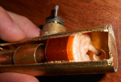
Couldn't see much from the outside and was never going to figure out exactly what was going on in here as-is. I'm not against a semi-destructive teardown at this point, because without knowing what's in here it was very unlikely I was going to be able to reuse any of this anyways (if it even works at this point, which is a long shot) so I very carefully sawed in two places along the length, just through the walls, and then circumferentially at each end too, to be able to remove a section from the wall and get a better view.

Ok, now that's interesting. There's clearly a coaxial resonator (the long rod in the middle is the center conductor), with some kind of active device partway along it.
The antenna connection is lightly coupled to the center conductor capacitively, partway down the length, with the flat circular piece on its end.
There's also a screw near the left end, which you can't see from this angle, but which I'm guessing moves closer to or further from the center conductor, adding a small variable capacitance and allowing for frequency tuning of some kind.
With the "homemade" RF capacitor at the right end forming an RF ground, therefore grounding both ends of the center conductor, its length is roughly correct for a half-wave resonator @ 4 Ghz. Now, with an active device sitting in the middle, it's not quite as simple as that, but it's a useful starting point.
For external connections, there's...
- A green wire leading to the left end, with an additional pin soldered to the housing (ground):

- A feed-through pin near the middle, connected to that wider circular section
- A feed-through pin at the right end, connected to the other wider circular section, pressed up against the outside with only a thin layer of polyimide tape in between, which looks like it's supposed to be an RF filtering cap (based on geometry, I calculated some 10s or 100s of pF value that ends up being a small fraction of an ohm @ 4 Ghz).
At this point I was stumped about the active device. I was expecting it to be similar to old 10 Ghz radar guns, which use either a tunnel diode or Gunn diode, biased into its negative-resistance region, as a microwave amplifier: when combined with a tuned cavity, this becomes a microwave oscillator. If it was a time-domain pulsed radar, though, then why would it have 3 separate DC connections into the RF section?
So an FMCW radar would make more sense (and be easier for timing!): this would be much easier with 70's tech anyways: less constraints on transmit pulse width, less constraints on precise echo timing, etc. A negative-resistance diode can't be tuned by DC bias alone though, so there would need to be (again, like an old 10 Ghz radar gun) a varactor in here somewhere to provide an electronically-controllable frequency adjustment. This would also make more sense with the external connections: you'd need at least 1 oscillator diode bias pin, and at least 1 varactor bias pin. The 2nd diode was probably hidden under that coaxial sheath in the middle of the RF section.
However, the continuity measurements from the external connections still didn't make sense. If there were two diodes in here, I should've been able to see a diode forward voltage with my meter's diode test mode between at least some of the external connections, but I saw no continuity between any of them.
Finally, though, I stumbled across a video by Gregory Charvat, where he looked at a Bonzer Mark-10 radar altimeter:
Besides this being pretty interesting on its own, there was a comment on the video that was very...illuminating:
@lynnpotter1810
Just a few comments to clear up some misconceptions: The Mark 10 is a 4.3 GHz super regenerative pulse radar utilizing a RCA pencil triode in a tuned cavity as both transmitter and receiver. As the cavity is grid pulsed it is susceptable to received energy. By measuring that susceptability it may be determined when there is reflected energy present. The pulse rate is swept from far to near range. When the received signal quits, that is your altitude. Testing the system was done with coaxial delay cables and actual test flying during development & production from 1965-1983. You were fortunate to find one that still had transmitter output. The tube life was rather short, less than a thousand hours. These units were rendered obsolete when RCA quit manufacturing pencil tubes/cavities in the early '80s. Lynn Potter - Bonzer VP/GM 1965-1977
Now it makes a lot more sense. This is a microwave triode:

The middle DC connection is to the grid, the left-end DC connections are to the filament, and the right-end DC connection is the plate supply.
The cathode has a 1/4 λ transmission line to ground, which I think would give it maximum "emitter degeneration" (don't know what the vacuum tube equivalent is called) at the operating frequency. The plate has a 3/4 λ resonator attached, with the antenna coupled partway along it. The grid "sheath" is 1/4 λ long before reaching the external feedthrough cap, which puts the far end of the grid sheath at RF ground, and gives a high impedance at the grid (at least un-loaded by the feedthrough cap). I'm not sure how to analyze the grid sheath from a distributed-element perspective though: there's obviously plate-to-grid coupling going on, but it's in the form of two nested lower-Z transmission lines rather than a typical coupler with two adjacent conductors. I guess when I draw it out as two nested transmission lines that it is, it looks like it's effectively an impedance divider feeding the grid a scaled copy of the plate voltage: but I'm not a full-time microwave guy so might be missing something here: the fact that the outer line is effectively shorted to ground at its end should change things too.

Plate-to-grid coupling makes sense, to provide the positive feedback for the super-regenerative oscillation. I'm not sure why you'd want a 1/4 λ resonator on the plate though, as that seems like the opposite of what would create gain and therefore oscillation: maybe it's meant to oscillate slightly off of the 1/4 λ frequency? I also don't entirely understand the explanation of how the super-regenerative part works - it sounds like maybe the oscillation stops upon receiving the return echo (disrupting the oscillation), or after a short transmit period the oscillation can only re-start (with lower bias/gain?) when the received signal provides some extra energy to the resonator? Any insights here much appreciated.
More to come, with analysis of the remaining non-RF circuitry.
(Edit: added RF schematic)


