Author Topic: Looking inside a military/aerospace RF phase shifter  (Read 1983 times)

0 Members and 1 Guest are viewing this topic.

Online D StraneyTopic starter

  • Regular Contributor
  • *
  • Posts: 189
  • Country: us
Looking inside a military/aerospace RF phase shifter
« on: September 02, 2023, 05:19:06 pm »
Continuing the series of mystery avionics items from good deals on eBay...
Here's a ruggedized RF phase shifter:

Looking up the part number on various parts-finder websites gave me this description:
Code: [Select]
Part Number PSD-4-30.7-27740
Electronic Phase Shifter
NIIN 011875136
National Stock Number:
5915-01-187-5136

Part Information
Shifter is digital 8-bit w/6 bits switch controlled and 2 bits internally wired to zero out; phases deg's 90, 45, 22.5, 11.25, 5.6 and 2.8 are switch controlled; internally wired phases 1.4 and 0.7 degs; freq 30.7465 mhz-porm 5 mhz; 50 ohms impedance; operating pwr 15 vdc at 100 ma; decoupling filters; rfi shielding; matl alum. Alloy covered w/zinc chromate and 2 coats of grey paint; female connectors; 1.250 in. D

The fact that it has a National Stock Number means that it was likely used in aerospace or military applications here in the US, maybe for radar or directional radio.  Looks like it was made by Merrimac Industries, now part of Crane Aerospace.

So you'd expect a chain of fixed phase shifts, selectively bypassed by PIN diodes used as RF switches, right?  Maybe one of the coax connectors is actually a serial data input?  Except...


...huh.  Nothing electronically-controllable anywhere I can see.

Ok, what exactly is happening in here?

It looks like the signal comes into one of the set-of-2 SMA connectors, and goes immediately into this metal can, which turns out to be a directional coupler (C-115.  The other SMA output next to it gets a -20 dB pickoff of either the forward or reverse signal.


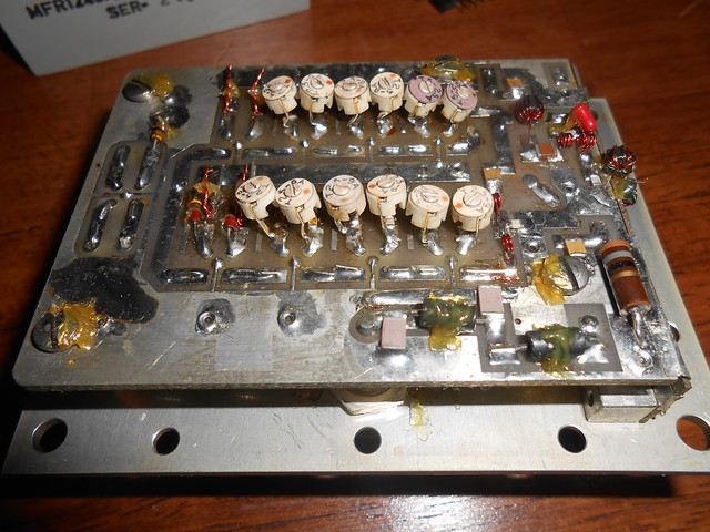
Next, the signal follows a U-shaped path through a chain of phase shifts made out of open metal can bases on the bottom side...

...and variable capacitors on the top side:

The variable caps on top, which presumably set the phase shift of each section, seem to descend from trimmers all the way from larger trimmers down to "gimmick capacitors" with short lengths of twisted wire.

The open metal cans hold a pair of toroids (with an unknown winding pattern, I can't see in there as it's too small), and a pi-shaped arrangement of SMT caps on the opposite side:

I'm not familiar enough with all-phase LC topologies off the top of my head to be able to speculate about the exact schematic of these.  Maybe with some more reading and continuity measurements.

After this phase shift section, the signal goes to an amplifier...

...and then a power splitter, where the output gets split up between all of the 4 SMA connectors at the other end of the box:

The single BNC connector seems to supply DC bias to the amplifier: you can see the 2 stages of LC filtering on the left in this photo, between the BNC connection and the amplifier.

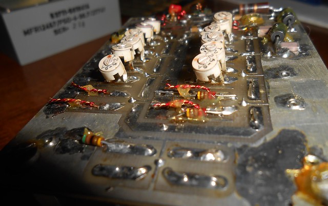
So how are the phase shifts selected?  From what I can tell, it looks like that's done with solder jumpers: see the closed jumpers inside the red boxes here, and the open jumpers inside the yellow box: these jumpers connect the far side of the variable caps for each stage to ground, and therefore make each individual phase shift either active or inactive.
(see attached image)

There's two things I'm confused about here.  The main one is: what's the use case?  The uses for an electronically-controlled phase shifter are obvious (electronically-steerable antennas with phased arrays, special noise cancellation or other techniques, etc.).  A fixed phase shift would also be useful (non-electronically-steerable antenna arrays, for example).  But if the phase is just set once at manufacturing, then you can just use a single LC and populate different components.  If the phase is meant to be adjustable in the field (when calibrating a system, for example), then you'd think a single trim cap (or a couple stages of trim caps) accessible from the outside with a screwdriver through a small hole in the box would be the way to go.  Making a factory-fixed phase shift by populating a whole lot of parts which go unused forever seems strange, and making an adjustable phase shift where you need to take out a bunch of screws every time to solder or de-solder a jumper also seems like way more of a pain than it should be.  Any insights appreciated.

I'm also a little surprised at how janky some of the construction is, for something that presumably is built for vibration, thermal cycling, etc.  The trimmer caps have their bodies just free-floating, cantilevered off of the pins which are surface-soldered-only to the board.  The "using SMT ceramic caps as structural elements" in the little pi-shaped arrangements shown above also does not give me warm fuzzy feelings about reliability either.  Most of the inductors on the top of the board are glued down, so it was obviously a consideration, just one that didn't seem to be applied consistently.

Anyways, hope this was interesting.
 
The following users thanked this post: xrunner, Neomys Sapiens, ch_scr

Offline TimFox

  • Super Contributor
  • ***
  • Posts: 7957
  • Country: us
  • Retired, now restoring antique test equipment
Re: Looking inside a military/aerospace RF phase shifter
« Reply #1 on: September 02, 2023, 05:31:17 pm »
Unfortunately, the Tusonix ceramic trimmer capacitors shown in your photos have gone out of production, but some are still in stock at normal vendors.
 

Offline coppercone2

  • Super Contributor
  • ***
  • Posts: 9468
  • Country: us
  • $
Re: Looking inside a military/aerospace RF phase shifter
« Reply #2 on: September 02, 2023, 06:56:25 pm »
what is the compound they are using for the glue or whatever it looks really bad like someone smear grease all over it.

also I hate the right angle PCB construction. a few pieces of hardware would have killed em for sure ::)
 

Offline mtwieg

  • Regular Contributor
  • *
  • Posts: 125
  • Country: us
Re: Looking inside a military/aerospace RF phase shifter
« Reply #3 on: September 04, 2023, 05:46:25 pm »
Interesting, thanks for sharing.
Quote
Ok, what exactly is happening in here?
Indeed, this is an interesting puzzle.

The more I look at this, the more I start to suspect that somebody used the housing for the phase shifter and tossed their own science project inside. That would explain why the circuitry doesn't resemble a phase shifter, and why the construction is so.... organic. Do any of the boards have any markings? I'd be shocked if a board in a milspec assembly didn't somehow identify the part number and board rev, at least.

Quote
The "using SMT ceramic caps as structural elements" in the little pi-shaped arrangements shown above also does not give me warm fuzzy feelings about reliability either.
I always called that "stonehenge" style construction. Not something I'd ever expect to see in mil-spec electronics.
 

Offline coppercone2

  • Super Contributor
  • ***
  • Posts: 9468
  • Country: us
  • $
Re: Looking inside a military/aerospace RF phase shifter
« Reply #4 on: September 04, 2023, 06:43:58 pm »
its kind of hard to  get away from with reliable structures though.

Ceramic scafolding? that can crack. then you have high momentum particles rattling around in there

plastic? their paranoid about problems with anything but the most simple geometric structures over time and conditions


and in one sense when you get down to bond wires, everything looks super hood. its like oh look someone welded a bread board jumper wires

there are screws on the bottom of the right angle pcb piece too, just noticed them under goop. that improves it alot.

but they could have bent the corner pieces out of thicker copper and soldered them with a lap flow tool from the bottom instead of just glazing them like a cake with solder
« Last Edit: September 04, 2023, 06:48:44 pm by coppercone2 »
 

Offline ywara

  • Contributor
  • Posts: 36
  • Country: us
Re: Looking inside a military/aerospace RF phase shifter
« Reply #5 on: September 06, 2023, 12:30:24 am »
You are looking at the wrong NSN.

You have PSD-4-30.7/27741, your NSN is for PSD-4-30.7/27740.

5915-01-187-5135:
Digital 8-bit, each bit permanently wired; deg phase shift per bit 90, 45, 22.5, 11.25, 5.6, 2.8, 1.4 and 0.7; freq range 30.7465 mhz porm 5 mhz; vswr 1.5; 50 ohms impedance; operating power 15 vdc at 115 ma; decoupling filters; rfi shielding; sma female connectors; power connector-bnc type female; matl-alum. Alloy; 1.250 in. O/a d

What this is for? No idea. But I guess if NAVSEA is buying it, it could be a very short run. There are only so many ships on the water. That could explain the... questionable engineering attention this thing seems to have received.
 
The following users thanked this post: Neomys Sapiens

Online D StraneyTopic starter

  • Regular Contributor
  • *
  • Posts: 189
  • Country: us
Re: Looking inside a military/aerospace RF phase shifter
« Reply #6 on: September 06, 2023, 03:48:07 pm »
Good catch!  That explains a lot, from a typo on my part there.

The more I look at this, the more I start to suspect that somebody used the housing for the phase shifter and tossed their own science project inside. That would explain why the circuitry doesn't resemble a phase shifter, and why the construction is so.... organic.

Ha, you know, that's what I would've thought too if not for it arriving in a (sealed) bag with the part number and official labeling - just made it weirder seeing the inside.


Share me

Digg  Facebook  SlashDot  Delicious  Technorati  Twitter  Google  Yahoo
Smf