Author Topic: Winding an Un-Un  (Read 9753 times)

0 Members and 1 Guest are viewing this topic.

Offline SquarewaveTopic starter

  • Frequent Contributor
  • **
  • Posts: 256
  • Country: gb
Winding an Un-Un
« on: May 13, 2022, 11:03:41 pm »
Hello.

I attempted to make my own 9:1 unun but something isn't quite right.

I have one which I bought years ago, so basically made a copy of it. I used my VNA to measure it with a 450ohm resistive load across the ground and antenna connection to give me an idea what to look for. It's a good match and the return loss is an acceptable level.

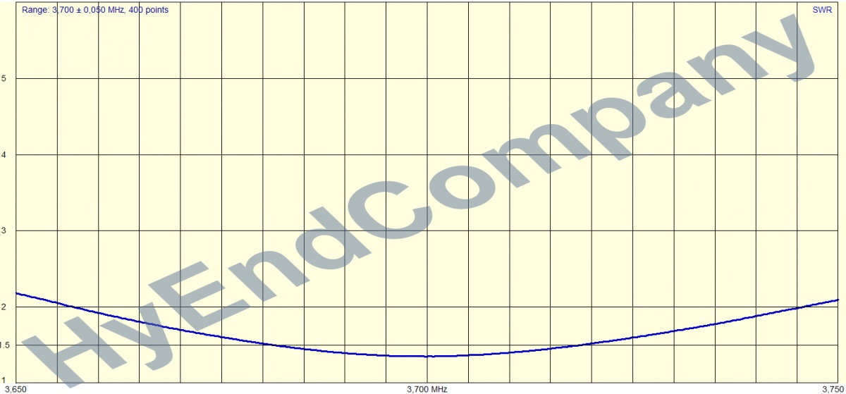
So the one I made is wound on FT140-43. Frequency sweep is 3mhz t0 30mhz. At the lower frequency end, it starts off ok, but then the SWR goes crazy high around midway across the sweep all the way to the end of the sweep.

I checked and checked and checked again, windings are ok, connections are ok, but for some reason, as the frequency goes up, so does the SWR and at the moment I'm lost as to why that is? Any ideas welcome!
 

Offline T3sl4co1l

  • Super Contributor
  • ***
  • Posts: 21672
  • Country: us
  • Expert, Analog Electronics, PCB Layout, EMC
    • Seven Transistor Labs
Re: Winding an Un-Un
« Reply #1 on: May 14, 2022, 03:40:55 am »
How many turns, how arranged?

Tim
Seven Transistor Labs, LLC
Electronic design, from concept to prototype.
Bringing a project to life?  Send me a message!
 

Offline A.Z.

  • Frequent Contributor
  • **
  • Posts: 881
  • Country: it
Re: Winding an Un-Un
« Reply #2 on: May 14, 2022, 07:04:06 am »
as said, it depends from the turns count which, in turn :) depends from the core material, in your case, start from this design

https://vk6ysf.com/unun_9-1_v3.htm

which uses your same core, then, willing to further flatten the response, you may experiment by inserting a fixed capacitor across the coax connection, a value between 100pF and 150pF may be a good starting point, just ensure that the capacitor can stand a voltage of at least 500V or (better) more

Also, ensure to use non inductive resistors for the 450 Ohm load, when running your VNA tests !
« Last Edit: May 14, 2022, 08:09:24 am by A.Z. »
 

Offline SquarewaveTopic starter

  • Frequent Contributor
  • **
  • Posts: 256
  • Country: gb
Re: Winding an Un-Un
« Reply #3 on: May 14, 2022, 10:23:31 am »
How many turns, how arranged?

Tim

Trifilar, started off with 5 like my bought unun, then tried 9 which other build threads have done, both no good.
 

Offline SquarewaveTopic starter

  • Frequent Contributor
  • **
  • Posts: 256
  • Country: gb
Re: Winding an Un-Un
« Reply #4 on: May 14, 2022, 10:26:14 am »
as said, it depends from the turns count which, in turn :) depends from the core material, in your case, start from this design

https://vk6ysf.com/unun_9-1_v3.htm

which uses your same core, then, willing to further flatten the response, you may experiment by inserting a fixed capacitor across the coax connection, a value between 100pF and 150pF may be a good starting point, just ensure that the capacitor can stand a voltage of at least 500V or (better) more

I'll try that one and see what happens.

The bought unun, I think is 43 material, but measures out to be a FT114-43 and uses two of them stacked. With my 140-43, I've tried two and one.

Also, ensure to use non inductive resistors for the 450 Ohm load, when running your VNA tests !

Yes, as I said above, resistive load.
 

Offline A.Z.

  • Frequent Contributor
  • **
  • Posts: 881
  • Country: it
Re: Winding an Un-Un
« Reply #5 on: May 14, 2022, 11:08:07 am »
as said, it depends from the turns count which, in turn :) depends from the core material, in your case, start from this design

https://vk6ysf.com/unun_9-1_v3.htm

which uses your same core, then, willing to further flatten the response, you may experiment by inserting a fixed capacitor across the coax connection, a value between 100pF and 150pF may be a good starting point, just ensure that the capacitor can stand a voltage of at least 500V or (better) more

I'll try that one and see what happens.

The bought unun, I think is 43 material, but measures out to be a FT114-43 and uses two of them stacked. With my 140-43, I've tried two and one.

Also, ensure to use non inductive resistors for the 450 Ohm load, when running your VNA tests !

Yes, as I said above, resistive load.

you "think" is a #43 or IS IT a #43 ? Because you can't tell the material from the toroid size ! And the material characteristics will determine the required windings, the rule of thumb, whenever choosing a material for a given RF transformer, is to pick the material type which, at the given frequency range, requires less windings; a good starting point for infos is

http://toroids.info/

then, if you are not familiar with RF transformers calculations, there are several online calculators which may help you; as for my capacitor suggestion, it will have negligible/no effect on a purely resistive load, to see what it does, you'll need to add some reactance ;)

« Last Edit: May 14, 2022, 11:09:58 am by A.Z. »
 

Offline SquarewaveTopic starter

  • Frequent Contributor
  • **
  • Posts: 256
  • Country: gb
Re: Winding an Un-Un
« Reply #6 on: May 14, 2022, 11:27:14 am »
The core I'm winding on is a 43, bought from a store selling Fairite branded cores.

The one I think is a 43, is the bought unun which measures spot on with the VNA.
 

Offline SquarewaveTopic starter

  • Frequent Contributor
  • **
  • Posts: 256
  • Country: gb
Re: Winding an Un-Un
« Reply #7 on: May 14, 2022, 11:33:52 am »
I'm winding now according to the website you linked to, then will pop in on the VNA for test.
 

Offline SquarewaveTopic starter

  • Frequent Contributor
  • **
  • Posts: 256
  • Country: gb
Re: Winding an Un-Un
« Reply #8 on: May 14, 2022, 11:57:41 am »
Exactly the same terrible results.

Go to the bought unun and it's fine  :-//
 

Offline MarkF

  • Super Contributor
  • ***
  • Posts: 2543
  • Country: us
Re: Winding an Un-Un
« Reply #9 on: May 14, 2022, 12:06:57 pm »
Not my bag.  But this might help.

https://youtu.be/VAV9Wws-Bs0?t=75
 

Offline SquarewaveTopic starter

  • Frequent Contributor
  • **
  • Posts: 256
  • Country: gb
Re: Winding an Un-Un
« Reply #10 on: May 14, 2022, 12:18:03 pm »
No, doesn't help, but thanks anyway.

So, no idea why, but if I do exactly the same as any build thread/video, I can't get it to work. It should be obvious that I'm doing something wrong, so I check, then check again, then again, it's exactly the same wind but the same terrible results.
 

Offline T3sl4co1l

  • Super Contributor
  • ***
  • Posts: 21672
  • Country: us
  • Expert, Analog Electronics, PCB Layout, EMC
    • Seven Transistor Labs
Re: Winding an Un-Un
« Reply #11 on: May 14, 2022, 02:45:55 pm »
Should be this one, for anyone curious.
https://www.fair-rite.com/product/toroids-5943002701/

So that's what, about 4cm turn length?  And it's three windings stacked to make an autoformer?  So the overall electrical length is 4cm * 5t * 3 = 60cm, or 1/4 wave about 125MHz, less velocity factor (twisted pair probably 80% so 100MHz).

Shouldn't be too bad.

LF limit is, let's see, AL = 0.8 so 5t is 20uH, somewhat less at ~MHz; into 50 ohms that's 0.4MHz cutoff.  So say 4x above that should be okay, which seems to be the case here.  Maybe more if you're putting a lot of power into it (watts?) because the core material is a bit lossy by some MHz.

Photo of the build?

Tim
Seven Transistor Labs, LLC
Electronic design, from concept to prototype.
Bringing a project to life?  Send me a message!
 

Offline Bud

  • Super Contributor
  • ***
  • Posts: 6910
  • Country: ca
Re: Winding an Un-Un
« Reply #12 on: May 14, 2022, 02:51:52 pm »
The bought unun, I think is 43 material, but measures out to be a FT114-43 and uses two of them stacked. With my 140-43, I've tried two and

The bought unun may actually have two different material cores to better cover the frequency range. Did you measure both cores or just one?
Facebook-free life and Rigol-free shack.
 

Offline A.Z.

  • Frequent Contributor
  • **
  • Posts: 881
  • Country: it
Re: Winding an Un-Un
« Reply #13 on: May 14, 2022, 02:58:35 pm »
No, doesn't help, but thanks anyway.

So, no idea why, but if I do exactly the same as any build thread/video, I can't get it to work. It should be obvious that I'm doing something wrong, so I check, then check again, then again, it's exactly the same wind but the same terrible results.

could you post some pics of the unun you wound ?
 

Offline SquarewaveTopic starter

  • Frequent Contributor
  • **
  • Posts: 256
  • Country: gb
Re: Winding an Un-Un
« Reply #14 on: May 14, 2022, 03:22:01 pm »
The bought unun, I think is 43 material, but measures out to be a FT114-43 and uses two of them stacked. With my 140-43, I've tried two and

The bought unun may actually have two different material cores to better cover the frequency range. Did you measure both cores or just one?

They look both the same in size, as the top one is easy to get to, that's what I measured.
 

Offline SquarewaveTopic starter

  • Frequent Contributor
  • **
  • Posts: 256
  • Country: gb
Re: Winding an Un-Un
« Reply #15 on: May 14, 2022, 03:23:52 pm »
No, doesn't help, but thanks anyway.

So, no idea why, but if I do exactly the same as any build thread/video, I can't get it to work. It should be obvious that I'm doing something wrong, so I check, then check again, then again, it's exactly the same wind but the same terrible results.

could you post some pics of the unun you wound ?

Should be this one, for anyone curious.
https://www.fair-rite.com/product/toroids-5943002701/

So that's what, about 4cm turn length?  And it's three windings stacked to make an autoformer?  So the overall electrical length is 4cm * 5t * 3 = 60cm, or 1/4 wave about 125MHz, less velocity factor (twisted pair probably 80% so 100MHz).

Shouldn't be too bad.

LF limit is, let's see, AL = 0.8 so 5t is 20uH, somewhat less at ~MHz; into 50 ohms that's 0.4MHz cutoff.  So say 4x above that should be okay, which seems to be the case here.  Maybe more if you're putting a lot of power into it (watts?) because the core material is a bit lossy by some MHz.

Photo of the build?

Tim

I'll post photos of what I've done so far. Two attempts have been taken apart for another attempt. Will also try again in a moment.
 

Offline A.Z.

  • Frequent Contributor
  • **
  • Posts: 881
  • Country: it
Re: Winding an Un-Un
« Reply #16 on: May 14, 2022, 03:36:03 pm »
if possible, post also some pics showing the setup you're using to measure your unun
 

Offline SquarewaveTopic starter

  • Frequent Contributor
  • **
  • Posts: 256
  • Country: gb
Re: Winding an Un-Un
« Reply #17 on: May 14, 2022, 03:44:56 pm »
Here's a photo of one I recently wound on a FT240-43 using 5 turns.

Results also attached.

I'll shortly put up the results for the bought unun and post a photo.
 

Offline SquarewaveTopic starter

  • Frequent Contributor
  • **
  • Posts: 256
  • Country: gb
Re: Winding an Un-Un
« Reply #18 on: May 14, 2022, 03:54:53 pm »
The bought Un Un


Offline SquarewaveTopic starter

  • Frequent Contributor
  • **
  • Posts: 256
  • Country: gb
Re: Winding an Un-Un
« Reply #19 on: May 14, 2022, 03:57:19 pm »
Oh, bare in mind, the small wire I'm using is for bench test purposes, I'm not wanting to waste any more enamelled copper wire.......
 

Offline SquarewaveTopic starter

  • Frequent Contributor
  • **
  • Posts: 256
  • Country: gb
Re: Winding an Un-Un
« Reply #20 on: May 14, 2022, 04:19:52 pm »
The enamelled wire on FT140-43


Offline A.Z.

  • Frequent Contributor
  • **
  • Posts: 881
  • Country: it
Re: Winding an Un-Un
« Reply #21 on: May 14, 2022, 04:42:44 pm »
Here's a photo of one I recently wound on a FT240-43 using 5 turns.

Results also attached.

I'll shortly put up the results for the bought unun and post a photo.

shorten those wires, lay them out properly to avoid parasite coupling and use a coax connector, also, maybe I'm wrong, but those resistors don't seem to be non inductive to me; your VNA setup to test your unun is badly screwed, imVHo
 

Offline SquarewaveTopic starter

  • Frequent Contributor
  • **
  • Posts: 256
  • Country: gb
Re: Winding an Un-Un
« Reply #22 on: May 14, 2022, 04:47:12 pm »
There is a coax connector.

Did you see the results for the bought unun? Do those results with the same resistors look unacceptable? I thought they were ok as at worse, SWR is just above 1.33 which is fine for matching.


Offline SquarewaveTopic starter

  • Frequent Contributor
  • **
  • Posts: 256
  • Country: gb
Re: Winding an Un-Un
« Reply #23 on: May 14, 2022, 05:27:22 pm »
Going to test this one next

Tested

« Last Edit: May 14, 2022, 05:41:37 pm by Squarewave »
 

Offline T3sl4co1l

  • Super Contributor
  • ***
  • Posts: 21672
  • Country: us
  • Expert, Analog Electronics, PCB Layout, EMC
    • Seven Transistor Labs
Re: Winding an Un-Un
« Reply #24 on: May 14, 2022, 05:44:17 pm »
The resistors are fine.  Carbon or metal film type axial resistors have a spiral stripe that becomes inductive up in the GHz (and even then, for fairly low R values, up to say 200-300 ohms; above which, lead capacitance dominates instead).

The stray wiring is not however!  Trim that tight and short between core and connector(s).

Tim
Seven Transistor Labs, LLC
Electronic design, from concept to prototype.
Bringing a project to life?  Send me a message!
 

Offline A.Z.

  • Frequent Contributor
  • **
  • Posts: 881
  • Country: it
Re: Winding an Un-Un
« Reply #25 on: May 14, 2022, 05:54:34 pm »
The resistors are fine.  Carbon or metal film type axial resistors have a spiral stripe that becomes inductive up in the GHz (and even then, for fairly low R values, up to say 200-300 ohms; above which, lead capacitance dominates instead).

The stray wiring is not however!  Trim that tight and short between core and connector(s).

Tim

ok for the resistors, but the wiring is screwed, it is like having a bunch of random inductors connected to the unun :(


Offline SquarewaveTopic starter

  • Frequent Contributor
  • **
  • Posts: 256
  • Country: gb
Re: Winding an Un-Un
« Reply #26 on: May 14, 2022, 05:57:17 pm »
Yes that appears to be what the problem was/is......but it was a little learning curve as I wanted to make my own and make one for a friend. Thanks everyone so far with your help and input on this one.
 

Offline A.Z.

  • Frequent Contributor
  • **
  • Posts: 881
  • Country: it
Re: Winding an Un-Un
« Reply #27 on: May 14, 2022, 07:09:43 pm »
Yes that appears to be what the problem was/is......but it was a little learning curve as I wanted to make my own and make one for a friend. Thanks everyone so far with your help and input on this one.

Come on, you can't leave us in a limbo ! Keep us updated about your progress, please !!
 

Offline SquarewaveTopic starter

  • Frequent Contributor
  • **
  • Posts: 256
  • Country: gb
Re: Winding an Un-Un
« Reply #28 on: May 14, 2022, 07:13:25 pm »
Post 23

Much better throughout. I'll do it again with the enamelled wire later and see what happens!
 

Offline A.Z.

  • Frequent Contributor
  • **
  • Posts: 881
  • Country: it
Re: Winding an Un-Un
« Reply #29 on: May 14, 2022, 10:20:40 pm »
Post 23

Much better throughout. I'll do it again with the enamelled wire later and see what happens!

thanks, keep us updated, please; then, if you want, please, take time to read this and reason a bit

https://cromwell-intl.com/radio/9-1-unun/

HTH
 

Offline SquarewaveTopic starter

  • Frequent Contributor
  • **
  • Posts: 256
  • Country: gb
Re: Winding an Un-Un
« Reply #30 on: May 14, 2022, 10:49:51 pm »
Thanks, will read that.

This is another FT140-43, with the enamelled wire, the arrangement isn't too tidy, as the wire is too thick really. For this size core, I really need a lighter gauge, but the results are very good.
The large croc clip is grounding the ground end of the winding to the coax socket ground.


Offline A.Z.

  • Frequent Contributor
  • **
  • Posts: 881
  • Country: it
Re: Winding an Un-Un
« Reply #31 on: May 15, 2022, 07:27:38 am »
much better now, you're on the right path

a suggestion; since a "random" endfed will have common mode even if used with a counterpoise, consider the idea of adding a choke to the coax feeder

http://www.karinya.net/g3txq/chokes/

as for the random antenna see here

https://udel.edu/~mm/ham/randomWire/

a good lenght is 25.6m (83ft) with the feedpoint at 9m (29.5ft) from ground and a counterpoise going down to ground (but not connected to it), optionally you may add some (insulated wire, as for the counterpoise and the antenna, #10 stranded, insulated will do) radials laying on ground and connected to the bottom of the counterpoise, if possible route the coax away from the antenna and place the choke at some distance or where the coax reaches ground, also, if possible, ground the coax braid right before entering the building/shack

HTH


« Last Edit: May 15, 2022, 08:47:18 am by A.Z. »
 

Offline SquarewaveTopic starter

  • Frequent Contributor
  • **
  • Posts: 256
  • Country: gb
Re: Winding an Un-Un
« Reply #32 on: May 15, 2022, 10:44:04 am »
Yes, I made a choke on FT240-31 with 17 turns of coax on it. I've had RF burn before, don't want that again  :palm:
 

Offline A.Z.

  • Frequent Contributor
  • **
  • Posts: 881
  • Country: it
Re: Winding an Un-Un
« Reply #33 on: May 15, 2022, 11:38:26 am »
Yes, I made a choke on FT240-31 with 17 turns of coax on it. I've had RF burn before, don't want that again  :palm:

In my experience, 17 turns of coax over a #43 toroid will serve you well over the whole HF band, then, in some conditions we may need to add a second choke for the "top bands" (160 and 80) wound on a #61; by the way, when it comes to unbalanced antennas like the endfed ones you will NEED a good counterpoise system AND a good choking system, otherwise your coax braid will work as part of the radiating system, and not only you'll risk RF burns, but your antenna will radiate in a SUB optimal way


« Last Edit: May 15, 2022, 03:04:49 pm by A.Z. »
 

Offline joeqsmith

  • Super Contributor
  • ***
  • Posts: 11737
  • Country: us
Re: Winding an Un-Un
« Reply #34 on: May 15, 2022, 06:56:52 pm »
I pulled out one of my old ARRL handbooks and saw they show a un-un 9:1 taking a much different approach.  They don't have a lot of information on it so I thought I would toss something together.   I pulled out a couple of TDK HF70 cores and wrapped some silver plated solid core Teflon insulation wire on it.   I didn't have a decent 450 ohm load so stuck a couple of 1ks together.  Their performance is poor beyond 110MHz. 

After putting it together, swept it from 20M-200M.  It's not real flat.   

Offline T3sl4co1l

  • Super Contributor
  • ***
  • Posts: 21672
  • Country: us
  • Expert, Analog Electronics, PCB Layout, EMC
    • Seven Transistor Labs
Re: Winding an Un-Un
« Reply #35 on: May 15, 2022, 08:04:00 pm »
For higher bandwidth, try a matched delay or Guanella type (the type shown above is Ruthroff).

This is constructed by wiring transmission lines in parallel at one end, and series at the other.  That is, consider a TL as a common mode choke.  By arranging some series-parallel combination on one end of a set of TLs, and a different series-parallel combination on the other, you can get any rational ratio you like (though going beyond quite small values of p, q (for ratio p/q) is rather bothersome).

By considering the CM voltages on each TL segment, and connecting them appropriately in each S/P stack, the number of turns for each TL on a common core can be determined.

For example, for a 9:1, you'd use 3 TLs in parallel on one side, wired in series on the other side.  Use Zo = 150 ohms, so the parallel combo presents 50 ohms to the source, and the series combo presents 450 ohms to the load.  The bandwidth is limited only by the TL width (i.e., breakup into higher TE/M modes) and how tightly you can arrange the parallel/series connections.  Only real delay is added, which as usual manifests as leakage inductance at LF, but does not incur the roll-off at HF that the mismatched delays of the Ruthroff design has.

Tim
Seven Transistor Labs, LLC
Electronic design, from concept to prototype.
Bringing a project to life?  Send me a message!
 
The following users thanked this post: cdev

Offline joeqsmith

  • Super Contributor
  • ***
  • Posts: 11737
  • Country: us
Re: Winding an Un-Un
« Reply #36 on: May 15, 2022, 09:12:58 pm »
Used a surface mount part for the load.  It's 420 ohms but at least it's well behaved.   Wound something similar to what was shown but on a much smaller core (Fair-Rite T75).    Decent in the 3-30MHz. 

Offline joeqsmith

  • Super Contributor
  • ***
  • Posts: 11737
  • Country: us
Re: Winding an Un-Un
« Reply #37 on: May 17, 2022, 12:42:02 am »
Using the same T75 material.   Changed the load to two 1206 909ohm resistors.   Wound a new transformer using five turns of 22AWG TFE insulation, silver coated wire.  This is a little larger diameter.   

I should be clear I have no use for this device.  It's purely for adding to the discussion and was made from materials I had on-hand.  I'm sure there are better core choices and obviously this core is far too small to handle much power.

Notice the twisted core.  This was also a six turns but was a total waste of time. 

Offline joeqsmith

  • Super Contributor
  • ***
  • Posts: 11737
  • Country: us
Re: Winding an Un-Un
« Reply #38 on: May 17, 2022, 12:53:13 am »
LiteVNA calibrated for lower range and swept from 3-30MHz.  Touchstone attached for comparison.

Offline joeqsmith

  • Super Contributor
  • ***
  • Posts: 11737
  • Country: us
Re: Winding an Un-Un
« Reply #39 on: May 17, 2022, 11:47:38 am »
Looks like I missed the picture of the last one. 

Offline T3sl4co1l

  • Super Contributor
  • ***
  • Posts: 21672
  • Country: us
  • Expert, Analog Electronics, PCB Layout, EMC
    • Seven Transistor Labs
Re: Winding an Un-Un
« Reply #40 on: May 17, 2022, 11:58:09 am »
Should be as good as you're going to get with that arrangement.

How 'bout the Guanella design? :D

Tim
Seven Transistor Labs, LLC
Electronic design, from concept to prototype.
Bringing a project to life?  Send me a message!
 

Offline A.Z.

  • Frequent Contributor
  • **
  • Posts: 881
  • Country: it
Re: Winding an Un-Un
« Reply #41 on: May 17, 2022, 12:57:11 pm »
Should be as good as you're going to get with that arrangement.

How 'bout the Guanella design? :D

Tim

a guanella for a 9:1 UnUn ?!?
 

Offline cdev

  • Super Contributor
  • ***
  • !
  • Posts: 7350
  • Country: 00
Re: Winding an Un-Un
« Reply #42 on: May 17, 2022, 10:29:00 pm »
A picture tells a thousand words,(old proverb) it really is true with so many things in electronics.

 
Should be this one, for anyone curious.
https://www.fair-rite.com/product/toroids-5943002701/

So that's what, about 4cm turn length?  And it's three windings stacked to make an autoformer?  So the overall electrical length is 4cm * 5t * 3 = 60cm, or 1/4 wave about 125MHz, less velocity factor (twisted pair probably 80% so 100MHz).

Shouldn't be too bad.

LF limit is, let's see, AL = 0.8 so 5t is 20uH, somewhat less at ~MHz; into 50 ohms that's 0.4MHz cutoff.  So say 4x above that should be okay, which seems to be the case here.  Maybe more if you're putting a lot of power into it (watts?) because the core material is a bit lossy by some MHz.

Photo of the build?

Tim

That is the design that I use for ununs but I try to twist the three wires together they work better if I do that, my first and second ununs which I used for years just had the windings wound semi randomly around the core (nine, more than on the web page) When I twisted the three wires together first it improved a bit. Mine use from nine to 12 turns. Its connected to around a 50 foot wire. around 35 feet above the ground. I am probably goping to put a vertical of some kind up soon. Maybe 43 feet.
"What the large print giveth, the small print taketh away."
 

Offline cdev

  • Super Contributor
  • ***
  • !
  • Posts: 7350
  • Country: 00
Re: Winding an Un-Un
« Reply #43 on: May 17, 2022, 11:03:42 pm »
Do this if your un-un has a decent counterpoise or ground at the un-un or at the antenna (and its fed by coax) Otherwise the shield is the ground. hat could be a very noisy ground. Mine is. Its truly horrible. I suspect one of the local power poles, maybe . Putting a ton of chokes on the coax helps a bit but not enough.

much better now, you're on the right path

a suggestion; since a "random" endfed will have common mode even if used with a counterpoise, consider the idea of adding a choke to the coax feeder

http://www.karinya.net/g3txq/chokes/

as for the random antenna see here

https://udel.edu/~mm/ham/randomWire/

a good lenght is 25.6m (83ft) with the feedpoint at 9m (29.5ft) from ground and a counterpoise going down to ground (but not connected to it), optionally you may add some (insulated wire, as for the counterpoise and the antenna, #10 stranded, insulated will do) radials laying on ground and connected to the bottom of the counterpoise, if possible route the coax away from the antenna and place the choke at some distance or where the coax reaches ground, also, if possible, ground the coax braid right before entering the building/shack

HTH
"What the large print giveth, the small print taketh away."
 

Offline joeqsmith

  • Super Contributor
  • ***
  • Posts: 11737
  • Country: us
Re: Winding an Un-Un
« Reply #44 on: May 18, 2022, 01:04:13 am »
Should be as good as you're going to get with that arrangement.

How 'bout the Guanella design? :D

Tim

Easy enough to make a small 9:1 BALUN.   

Looking at his early papers, I guess my common mode transformers would be considered a Guanella design as well.   I would expect them to be prior art but maybe they didn't have Google patents back then...

Offline joeqsmith

  • Super Contributor
  • ***
  • Posts: 11737
  • Country: us
Re: Winding an Un-Un
« Reply #45 on: May 18, 2022, 02:17:48 am »
Mounted to a test board, used surface mount for the load and sweeping from 20MHz to 200MHz.  Again, just what cores I have on-hand and I'm sure it could be improved. 

I am interested in seeing how this 1:9 UNUN is constructed.   Post a few pictures of it along with test results.

Offline joeqsmith

  • Super Contributor
  • ***
  • Posts: 11737
  • Country: us
Re: Winding an Un-Un
« Reply #46 on: May 19, 2022, 01:12:15 am »
9:1 UnUn made from 4X HT70 TDK cores, 22AWG Teflon silver plated, 9 turns each. 

Offline metrologist

  • Super Contributor
  • ***
  • Posts: 2199
  • Country: 00
Re: Winding an Un-Un
« Reply #47 on: May 19, 2022, 12:36:25 pm »
Oh, I just wanted to play too. I named this file 25t balun and I remember I was trying to match my SDR I or Q input. No fancy VNA measurement this time.

« Last Edit: May 19, 2022, 12:44:19 pm by metrologist »
 

Offline A.Z.

  • Frequent Contributor
  • **
  • Posts: 881
  • Country: it
Re: Winding an Un-Un
« Reply #48 on: May 19, 2022, 04:06:23 pm »
Oh, I just wanted to play too. I named this file 25t balun and I remember I was trying to match my SDR I or Q input. No fancy VNA measurement this time.

Well, if you have fun winding impedance transformers, you may like this reference

http://www.introni.it/pdf/Amidon%20-%20Transmission%20Line%20Transformers%20Handbook.pdf


The following users thanked this post: bingo600, metrologist

Offline joeqsmith

  • Super Contributor
  • ***
  • Posts: 11737
  • Country: us
Re: Winding an Un-Un
« Reply #49 on: May 19, 2022, 04:45:23 pm »
After taking the time to build them, it seems appropriate to put a little power through them.   Not being a radio hobbyist, I'm not really setup for it.   I don't have any sort of load so I made up an array of 16 X 2W 470ohm Ohmite parts.   I started out at 3MHz using a small home made amplifier.   I don't have an in-line Watt meter but the supply was running about 40W.  Load required fan cooling.   My childhood VSWR meter seems to show something decent. 


Offline joeqsmith

  • Super Contributor
  • ***
  • Posts: 11737
  • Country: us
Re: Winding an Un-Un
« Reply #50 on: May 19, 2022, 04:56:16 pm »
That amplifier is limited to about 14MHz.   I drug out another that will get us to 30MHz.   SWR is much worse as expected.   I took the power up higher and am using both fans to now cool the load but they are still well over 100C.   :-DD

Offline joeqsmith

  • Super Contributor
  • ***
  • Posts: 11737
  • Country: us
Re: Winding an Un-Un
« Reply #51 on: May 19, 2022, 08:31:16 pm »
2:1 even with our poor mans load seems really high.   So back to the VNA and it looks like it should be closer to 1.5:1.   Of course, I have no idea how well my vintage Mars VSWR meter works.  With it being an UnUn,  I used a 100X probe and attached my scope across the load to have a look. 

I started with 19.4V or roughly 800mW at our load.   The waveform seemed fine so I bumped it up to 48.9V or about 5.1 Watts.  Again, the waveform seems fine and the VSWR looks like we would expect based on the LiteVNA.   

The resistors are rated for 2Watts each so the load should easily handle 30Watts.  With it getting so hot with the two fans, I was putting out a lot more power.  So I bumped it to 152.8V or roughly 50Watts.   The VSWR goes up and now we see the problem. 

Offline T3sl4co1l

  • Super Contributor
  • ***
  • Posts: 21672
  • Country: us
  • Expert, Analog Electronics, PCB Layout, EMC
    • Seven Transistor Labs
Re: Winding an Un-Un
« Reply #52 on: May 19, 2022, 08:56:01 pm »
Poor cores! :D How hot were they getting?

Or is that the amp's problem?

Tim
Seven Transistor Labs, LLC
Electronic design, from concept to prototype.
Bringing a project to life?  Send me a message!
 

Offline joeqsmith

  • Super Contributor
  • ***
  • Posts: 11737
  • Country: us
Re: Winding an Un-Un
« Reply #53 on: May 19, 2022, 09:34:04 pm »
To answer this,  I have other PAs, however I keep this vintage radio in the lab.  It seemed like a good use for it.   A bit on the scary side  267.9V or 152Watts on our poor little resistor load.  I only keyed it long enough to capture the waveform with the DSO,  set the VSWR meter and take a picture.   :phew: :-DD    Those resistors were not made for this kind of abuse.

So, the UnUn is fine but I was pushing my little amplifier.    Good to see the old Drake's tubes light up. 

Offline joeqsmith

  • Super Contributor
  • ***
  • Posts: 11737
  • Country: us
Re: Winding an Un-Un
« Reply #54 on: May 19, 2022, 09:38:07 pm »
I should say poor little VSWR meter too.  I don't have the manual for it but doubt it was rated for that much power.   

Offline T3sl4co1l

  • Super Contributor
  • ***
  • Posts: 21672
  • Country: us
  • Expert, Analog Electronics, PCB Layout, EMC
    • Seven Transistor Labs
Re: Winding an Un-Un
« Reply #55 on: May 19, 2022, 09:39:08 pm »
TOOB!  ^-^

Aha, well that does it. :)

Are the cores getting hot, warm at all even, in any of these--?

Tim
Seven Transistor Labs, LLC
Electronic design, from concept to prototype.
Bringing a project to life?  Send me a message!
 

Offline joeqsmith

  • Super Contributor
  • ***
  • Posts: 11737
  • Country: us
Re: Winding an Un-Un
« Reply #56 on: May 19, 2022, 09:52:05 pm »
Well, nothing has unsoldered and the Kapton tape is still in place.  Without a better load the best I could do is run it around 40W or so and see what the heat rise is.  I would guess most of it would be conducted from the load.    Now if we want to talk heat, that old radio is throwing off a fair amount.    :-DD

Offline cdev

  • Super Contributor
  • ***
  • !
  • Posts: 7350
  • Country: 00
Re: Winding an Un-Un
« Reply #57 on: May 19, 2022, 10:25:53 pm »
A while back I asked about favorite wire to use making ununs. I still have not found the ideal hi temp wire, so over the years several times Ive use a medium size of enameled solid copper wire. Thats worked okay for receiving. But I would kind of like to acquire something better. For a full power capable ham unun, what gauge of teflon wire would you use? I'm probably going to use two toroid cores. #43 ferrite. IS that a good choice or would y-all. (spoken in my best Memphis drawl) prefer something else?

I like using different colors of wire too. To make pretty, easy to understand pictures. I have teflon plumbers tape (which also makes a good ulta white card for photographic purposes, should I wrap the toroids with that stuff first, do you think, so they dont/can't arc over?

Otherwise I'll probably just use my 18 gauge solid copper enameled wire again. The insulation seems to work well, when ive tested it. Maybe I can find some thin, translucent teflon tubing for it?

« Last Edit: May 19, 2022, 10:40:41 pm by cdev »
"What the large print giveth, the small print taketh away."
 

Offline joeqsmith

  • Super Contributor
  • ***
  • Posts: 11737
  • Country: us
Re: Winding an Un-Un
« Reply #58 on: May 19, 2022, 10:26:44 pm »
I placed a layer of Pyrople (Polyimide fiber board) between the two cores and load.  I placed TCs on each core and blocked the majority of air flow around them.   I brought the power up to roughly 40Watts and let it stabilize.   The load is sitting over 100C but the cores remain well below 50.   Hard to say how much of this is conduction.   

Maybe one of the CB or Hams will jump in with some better data. 

Offline cdev

  • Super Contributor
  • ***
  • !
  • Posts: 7350
  • Country: 00
Re: Winding an Un-Un
« Reply #59 on: May 19, 2022, 10:36:32 pm »
Orange Skotchbrite Kind of,  That's a new one for me.. Have you used it for anything else? I guess its originally for cleaning stuff while its hot? Yup, Google is helpful here.. Definitely looks useful for holding or juggling hot and spicy ununs, quite possibly. They are sold as griddle pads.. for cleaning hot griddles in-situ.

Just a wild guess.. Presumably it works at that? Ive never made a balun like that but I do like using binocular cores for baluns (and ununs, which also works, )and my experience is that that works really well. Enclosing the winding lets it be shorter, so it works better at higher frequencies as well as low. My switchable imitation elecraft BL-2 balun works at both all of HF and at 6 meters.
« Last Edit: May 19, 2022, 10:44:56 pm by cdev »
"What the large print giveth, the small print taketh away."
 

Offline joeqsmith

  • Super Contributor
  • ***
  • Posts: 11737
  • Country: us
Re: Winding an Un-Un
« Reply #60 on: May 19, 2022, 11:08:10 pm »
https://pyropelinc.com/
No it's not a Scotch-Brite pad.  Yes, I have shown using Pyropel a few times on this site.   

https://www.eevblog.com/forum/projects/waveforms-in-a-74ls04-ring-oscillator/msg648003/#msg648003

Offline joeqsmith

  • Super Contributor
  • ***
  • Posts: 11737
  • Country: us
Re: Winding an Un-Un
« Reply #61 on: May 19, 2022, 11:55:27 pm »
Touching the PA made a rapid change in the BM869s temperature readings.   |O   Added some ferrite to the TC leads which has seemed to tamed the problem.   The singles didn't help.  The common mode one did the trick.    Readings are now believable.   


Offline joeqsmith

  • Super Contributor
  • ***
  • Posts: 11737
  • Country: us
Re: Winding an Un-Un
« Reply #62 on: May 20, 2022, 12:12:59 am »
Showing the whole setup, no camera flash so you can watch the fans.  Note 2:1 SWR from over driving the small solid-state amp.  Cores remaining nice and cool.

Offline T3sl4co1l

  • Super Contributor
  • ***
  • Posts: 21672
  • Country: us
  • Expert, Analog Electronics, PCB Layout, EMC
    • Seven Transistor Labs
Re: Winding an Un-Un
« Reply #63 on: May 20, 2022, 12:20:29 pm »
Nice. ;D

Tim
Seven Transistor Labs, LLC
Electronic design, from concept to prototype.
Bringing a project to life?  Send me a message!
 

Offline joeqsmith

  • Super Contributor
  • ***
  • Posts: 11737
  • Country: us
Re: Winding an Un-Un
« Reply #64 on: May 20, 2022, 02:02:34 pm »
I let it run for a few hours like this and nothing changed.  I removed the two single clamp-on cores beads with no effect. 

I was curious about the temperature and tried two BM869s meters rather than one.  The inputs are not isolated and with the probes attached to the cores, there may be some common mode.   It had no effect.   As soon as I remove the common mode core, the both meters display very high temperatures...

One reason I bought the BM869s was because it has two TC inputs.   The one other meter I have that has this feature is the UNI-T UT181A.  While mine works fine without the common mode bead attached, it is no longer a stock meter.  This meter, like pretty much all UNI-T products I have looked at, was very sensitive to ESD which damaged the meter.  After repairs, I modified the meter which would certainly improve the high frequency rejection.   The UNI-T fanboys would need to check a stock one. 

The new Brymen BM78x supports two TC inputs but sadly, it is a single display only so you have to select between the two.   I tried it out and as you can see, it is also way off.  Adding the bead corrects the measurement.   

Offline T3sl4co1l

  • Super Contributor
  • ***
  • Posts: 21672
  • Country: us
  • Expert, Analog Electronics, PCB Layout, EMC
    • Seven Transistor Labs
Re: Winding an Un-Un
« Reply #65 on: May 20, 2022, 02:16:52 pm »
Have also noticed poor CMRR on the BM235, mainly just an issue when probing a heatsink / transistor tab / pin and the TC ball touches a switching node and the reading goes kablooie.  Seems fine as long as it's not touching.  In your case, probably it's similar immunity (or lack thereof), but being nestled down inside a network at even higher voltages*, it has similar effect.

*In my case, switching nodes, so, 100s kHz at 100s of V, but harmonics in the 10s MHz range then are only some ~V.  So your case is probably the more aggressive -- give or take if it's more sensitive to impulsive or CW noise, or what effect those have on the acquisition, etc..

Tim
Seven Transistor Labs, LLC
Electronic design, from concept to prototype.
Bringing a project to life?  Send me a message!
 

Offline joeqsmith

  • Super Contributor
  • ***
  • Posts: 11737
  • Country: us
Re: Winding an Un-Un
« Reply #66 on: May 20, 2022, 02:25:20 pm »
Are you also using beads to combat the problem with your BM235? 

Offline T3sl4co1l

  • Super Contributor
  • ***
  • Posts: 21672
  • Country: us
  • Expert, Analog Electronics, PCB Layout, EMC
    • Seven Transistor Labs
Re: Winding an Un-Un
« Reply #67 on: May 20, 2022, 02:27:03 pm »
I forget if beads helped.  That was just a matter of, better choice of pin or package spot to probe, so, I didn't look into it.  Likely it would.

Tim
Seven Transistor Labs, LLC
Electronic design, from concept to prototype.
Bringing a project to life?  Send me a message!
 

Offline joeqsmith

  • Super Contributor
  • ***
  • Posts: 11737
  • Country: us
Re: Winding an Un-Un
« Reply #68 on: May 20, 2022, 02:45:03 pm »
My 189 with the same setup.  Over driving that amplifier is making some harmonics. 

Offline joeqsmith

  • Super Contributor
  • ***
  • Posts: 11737
  • Country: us
Re: Winding an Un-Un
« Reply #69 on: May 20, 2022, 07:08:12 pm »
With no goals and constraints, here is a coaxial wound 9:1 UnUn.    Performance is very poor.   

Offline T3sl4co1l

  • Super Contributor
  • ***
  • Posts: 21672
  • Country: us
  • Expert, Analog Electronics, PCB Layout, EMC
    • Seven Transistor Labs
Re: Winding an Un-Un
« Reply #70 on: May 20, 2022, 08:32:32 pm »
Probably too low shield impedance; looser spacing on larger cores, or fewer turns, might do better.

Considering 450 ohms needs ladder line, the multi-filar (parallel laid) design is pretty good.  Would need pretty gross geometry coax to improve on it at all. :-+

Tim
Seven Transistor Labs, LLC
Electronic design, from concept to prototype.
Bringing a project to life?  Send me a message!
 

Offline A.Z.

  • Frequent Contributor
  • **
  • Posts: 881
  • Country: it
Re: Winding an Un-Un
« Reply #71 on: May 20, 2022, 09:09:11 pm »
With no goals and constraints, here is a coaxial wound 9:1 UnUn.    Performance is very poor.

I'll refrain

https://cromwell-intl.com/radio/9-1-unun/


Offline joeqsmith

  • Super Contributor
  • ***
  • Posts: 11737
  • Country: us
Re: Winding an Un-Un
« Reply #72 on: May 20, 2022, 10:50:53 pm »
It would provide decent results down to about 500kHz, so yes, too many turns.  After removing a third, it was still poor.   

Shown after removing the turns with a 220, 450 and 900 ohm load.   I'm using my substitution box which of course is going to skew the results but at least we can see the transformer is doing something.   Also shown is the substitution box compared with a 1/4W TH. 

Offline joeqsmith

  • Super Contributor
  • ***
  • Posts: 11737
  • Country: us
Re: Winding an Un-Un
« Reply #73 on: May 21, 2022, 12:41:39 am »
Shown with 4 turns with the substitution box set to 220, 450 & 900.   Sweeping from 1.8-21.6MHz.   It's not quite as bad as it looks as that substitution box is adding a lot of error.  Still, not very good.    Maybe pull one more turn off and see how bad it hurts the low end.   

Offline joeqsmith

  • Super Contributor
  • ***
  • Posts: 11737
  • Country: us
Re: Winding an Un-Un
« Reply #74 on: May 21, 2022, 01:51:10 am »
Brings the high end down to around 2:1 VSWR but the low end really suffers. 

Offline A.Z.

  • Frequent Contributor
  • **
  • Posts: 881
  • Country: it
Re: Winding an Un-Un
« Reply #75 on: May 21, 2022, 07:53:31 am »
 

Offline joeqsmith

  • Super Contributor
  • ***
  • Posts: 11737
  • Country: us
Re: Winding an Un-Un
« Reply #76 on: May 21, 2022, 02:09:30 pm »
With no goals and constraints, here is a coaxial wound 9:1 UnUn.    Performance is very poor.

I'll refrain

https://cromwell-intl.com/radio/9-1-unun/

and also

http://www.warc.asn.au/wp-content/uploads/2018/09/tube-baluns.pdf

The first link shows the typical 9:1 UnUn while your second link is about BalUns.   I assumed from the title, the goal was to make an UnUn.  Specifically a 9:1.  The OP was only testing from 3-30MHz,  with a worse case VSWR of 1.4:1.   

Again, I want to be clear that I have no use for such a device and am only playing around.  Electronics is one of my hobbies and I enjoy experimenting.  That does not mean that I like to copy and paste.   Do a search on youtube for 1:9 unun.   Outside of different colors of wire and a few different material selections, they all are similar to the one shown in your first link.  Once in a while, someone may even show a little data from theirs.   That's nothing I have any interest in.  I would rather spend my time experiment with other ideas and fail.  That last coaxial core would work well below 1MHz but the high end suffered.   Time for some new material. 

Let's see what you have put together. 

****
I have accumulated a box of materials over the years.  Some I kept marked, others are unknown.   Sorting through them to see what else I have that could work, that 45mm core looks very interesting.   I have another that is roughly 37mm that appears to be the same material but not a matched set.   Easy enough to try it with the OPs construction but going with the twin core would certainly help with the higher end.    The core to the far right is another that would be very interesting to try.   
« Last Edit: May 21, 2022, 04:28:26 pm by joeqsmith »
 

Offline A.Z.

  • Frequent Contributor
  • **
  • Posts: 881
  • Country: it
Re: Winding an Un-Un
« Reply #77 on: May 21, 2022, 04:49:46 pm »
Joe, probably I was unclear; the first link in the message you quoted, shows how to properly calculate the windings and also shows that it's important to know the characteristics of the core material one is using, trial and error isn't exactly the best line of action, in my humble opinion; then, as for the second link, I posted it mainly to show the "flattening" effect (on the SWR curve) which can be obtained by placing a capacitor across the winding, no miracles by the way, but if one starts knowing the core material and calculating the windings, the resulting transformer will be in the ballpark and may just need some tiny adjustment, at that point, willing to flatten the response curve (given it will be needed) would just mean adding a capacitor and adjusting its value

hope to have made my point more clear now
« Last Edit: May 21, 2022, 04:55:56 pm by A.Z. »
 

Offline joeqsmith

  • Super Contributor
  • ***
  • Posts: 11737
  • Country: us
Re: Winding an Un-Un
« Reply #78 on: May 21, 2022, 04:51:26 pm »
Notice how the OPs purchased unit is starting to peak back up below 3MHz.   These other parts I have should be good below a MHz. 
https://www.eevblog.com/forum/rf-microwave/winding-an-un-un/msg4174312/#msg4174312

Starting with the smaller 36mm core (larger than what I have shown so far),  using the resistor substitution box set to 225, 450 & 900 ohms.   I swept from 400Khz to 4MHz.   Again, I'm just using that box of resistors to get some idea how the transformer behaves.   At 4MHz the LiteVNA is showing a VSWR of 1.32:1 which I expect if due to the load.

Offline A.Z.

  • Frequent Contributor
  • **
  • Posts: 881
  • Country: it
Re: Winding an Un-Un
« Reply #79 on: May 21, 2022, 04:59:01 pm »
Either a #43 or a #61 core will get at least down to around 1MHz, although the #61 will require more turns, but if one doesn't know the core material, then it will just become a wild guess game :P
 

Offline joeqsmith

  • Super Contributor
  • ***
  • Posts: 11737
  • Country: us
Re: Winding an Un-Un
« Reply #80 on: May 21, 2022, 05:02:54 pm »
Why would you think I had not made any calculations?  Note he just provides the same basics that everyone else shows.  It's nothing new.   Same for measuring the cores I have.  Do you really think I am just randomly grabbing parts and winding them up?   :palm:   

Again, looking forward to seeing what YOU have done?  Google foo counts for nothing...

Swapping out the load for the 1/4W axial,  the low end VSWR now looks like I would expect.  Good for the radio guys playing in the 160 meter band. 

Offline joeqsmith

  • Super Contributor
  • ***
  • Posts: 11737
  • Country: us
Re: Winding an Un-Un
« Reply #81 on: May 21, 2022, 05:14:25 pm »
Sweeping the core from 1.8MHz to 29.7MHz.   I doubt the radio hobbyist do much with UnUns outside of that range.  Not bad for guessing... :-DD 

Offline A.Z.

  • Frequent Contributor
  • **
  • Posts: 881
  • Country: it
Re: Winding an Un-Un
« Reply #82 on: May 21, 2022, 05:18:06 pm »
Oh, so your point is "show me yours"; sorry but I stopped building stuff quite some years ago, and... yes, reading what you wrote, my impression was that you were picking "random" cores from your "junk box", winding some turns and then playing with VNA, then maybe I was under the wrong impression
 

Offline joeqsmith

  • Super Contributor
  • ***
  • Posts: 11737
  • Country: us
Re: Winding an Un-Un
« Reply #83 on: May 21, 2022, 05:37:40 pm »
Oh, so your point is "show me yours"; sorry but I stopped building stuff quite some years ago, and... yes, reading what you wrote, my impression was that you were picking "random" cores from your "junk box", winding some turns and then playing with VNA, then maybe I was under the wrong impression

It wasn't a point but a request to see what you personally had done.  I was under the impression you were an armchair engineer and was wondering if I had the wrong impression.

Even if I am just a pretty good guesser in your eyes and I can live with that.

Offline A.Z.

  • Frequent Contributor
  • **
  • Posts: 881
  • Country: it
Re: Winding an Un-Un
« Reply #84 on: May 21, 2022, 06:51:08 pm »
Oh, so your point is "show me yours"; sorry but I stopped building stuff quite some years ago, and... yes, reading what you wrote, my impression was that you were picking "random" cores from your "junk box", winding some turns and then playing with VNA, then maybe I was under the wrong impression

It wasn't a point but a request to see what you personally had done.  I was under the impression you were an armchair engineer and was wondering if I had the wrong impression.

Even if I am just a pretty good guesser in your eyes and I can live with that.

well, all in all your impression was correct, due to personal issues, as of today I AM an "armchair" engineer ... and almost a "wheelchair" one, but I was lucky

Just to be clear, I'm not asking for anything at all, I'm able to stand to my ideas, not asking for whatever, so feel free to criticize, I was not "begging"; hope it's clear now


« Last Edit: May 21, 2022, 08:57:03 pm by A.Z. »
 

Offline joeqsmith

  • Super Contributor
  • ***
  • Posts: 11737
  • Country: us
Re: Winding an Un-Un
« Reply #85 on: May 21, 2022, 09:56:25 pm »
Electronics is the least physically demanding hobby I have.  Most of the time I spend sitting in a chair at the bench or my desk. 

My cheap resistor substitution box.  And now you see where a lot of the error comes from.   :-DD   All part of the fun.

Rebuilt the coaxial transformer using 18AWG silver coated Teflon wire.  Good for a KV.   Time for a much larger load....

****
Used a combination of wire wound resistors along with the LiteVNA to pick a few sweet spots in the ham bands with decent VSWR.   
« Last Edit: May 22, 2022, 12:17:50 am by joeqsmith »
 

Offline joeqsmith

  • Super Contributor
  • ***
  • Posts: 11737
  • Country: us
Re: Winding an Un-Un
« Reply #86 on: May 22, 2022, 01:53:18 am »
I'll replace the little VSWR meter and smaller coax with a section of larger coax before turning  it up further. 

Offline joeqsmith

  • Super Contributor
  • ***
  • Posts: 11737
  • Country: us
Re: Winding an Un-Un
« Reply #87 on: May 22, 2022, 03:41:11 pm »
I had tried the larger coax and let it run at higher power levels for about an hour.  Once again the  Brymen meter, even with the one bead is showing about 10C of error.  Once I turned the amplifier off to see the actual core temperatures, they were around 28C.   
« Last Edit: May 22, 2022, 03:49:12 pm by joeqsmith »
 

Offline joeqsmith

  • Super Contributor
  • ***
  • Posts: 11737
  • Country: us
Re: Winding an Un-Un
« Reply #88 on: May 22, 2022, 03:56:32 pm »
Last attempt was to test that last larger 44mm core.  After making a few measurements, I believe this part is made from HF90.  I believe that last smaller core was the same material.   This is also 5 turns with 18AWG silver coated Teflon insulated wire.   

Showing VSWR using the axial resistor from 400kHz to 4MHz and again from 1.8MHz to 29.7MMHz.   

Offline joeqsmith

  • Super Contributor
  • ***
  • Posts: 11737
  • Country: us
Re: Winding an Un-Un
« Reply #89 on: May 22, 2022, 04:02:49 pm »
The load is a problem so I ran the last two transformers back-to-back.  I rebuilt an old 100W JWF attenuator a while back and will use this as the load.   With forced air cooling, I have ran it over 200 Watts.

Showing VSWR from 1.8-29.7MHz with the terminated attenuator and two transformers.   Much better than the WW resistors....

Offline joeqsmith

  • Super Contributor
  • ***
  • Posts: 11737
  • Country: us
Re: Winding an Un-Un
« Reply #90 on: May 22, 2022, 04:27:13 pm »
The Fluke 189s were used to measure the temperature of the two transformers (without additional ferrite).  At 30MHz the VSWR is roughly 1.5.  Even at 100 Watts the HF90 core is already starting to heat up.   It's warm to the touch.   

That second picture was taken after about an hour.  Obviously the radio hobbyist is not running at 100% duty cycle.   Or are they??!! :-DD   

The other transformer is 8 pcs of 31mm HF70 material.    Guessing that TDK HF90 would be a good choice but I think they have been obsoleting some of this material.

Offline joeqsmith

  • Super Contributor
  • ***
  • Posts: 11737
  • Country: us
Re: Winding an Un-Un
« Reply #91 on: May 22, 2022, 05:06:09 pm »
Removing the old SWR meter and running at about 300Watts.  The amplifier isn't going to bat an eye at these levels.   The Kapton tape has started to smell and delaminate.   Touching the core, yeah, it's that hot!  I cut the power and measured the core temps after about a minute and it's still well over 100C.   The 8-core unit stayed nice and cool.

Well, not sure if any of that was helpful or not.  Entertaining for me anyway. 

Offline T3sl4co1l

  • Super Contributor
  • ***
  • Posts: 21672
  • Country: us
  • Expert, Analog Electronics, PCB Layout, EMC
    • Seven Transistor Labs
Re: Winding an Un-Un
« Reply #92 on: May 22, 2022, 06:04:41 pm »
Time to invest in some silicone adhesive polyimide tape!

That it's available with rubber adhesive surely must be some kind of joke... :P

Tim
Seven Transistor Labs, LLC
Electronic design, from concept to prototype.
Bringing a project to life?  Send me a message!
 

Offline joeqsmith

  • Super Contributor
  • ***
  • Posts: 11737
  • Country: us
Re: Winding an Un-Un
« Reply #93 on: May 22, 2022, 07:08:24 pm »
I've use Kapton tape for all sorts of projects.  Some can be used above 300C.  I will use it as an insulator when modifying boards as I can solder components laying on the tape.   
We had a PCB made from polyimide for a high temp application.   Good stuff.   Check 3Ms catalog:

https://multimedia.3m.com/mws/media/1705914O/3m-high-temperature-tapes-product-selection-guide.pdf

Before cleaning up the mess, I did flip the two transformers so I was driving the T90 core with the load on the T70.  I placed the VSWR meter back in-line.  I also flipped the meters at TCs.    Ran it at about 100W for a while and the single T90 core started to heat up right away.  VSWR was a wash.  So nothing funny going on there. 

Offline joeqsmith

  • Super Contributor
  • ***
  • Posts: 11737
  • Country: us
Re: Winding an Un-Un
« Reply #94 on: May 25, 2022, 12:54:38 pm »
Thinking to purchase a commercial UnUn to see how it performs.   Looking around many are receive only or kits.   I would rather stay away from a kit.  Not that I'm concerned about assembling one, but it would raise questions if there was a problem. 

Any advice on such a product? 

Offline virtualparticles

  • Regular Contributor
  • *
  • Posts: 137
  • Country: us
Re: Winding an Un-Un
« Reply #95 on: June 01, 2022, 12:05:51 pm »
The resistors are fine.  Carbon or metal film type axial resistors have a spiral stripe that becomes inductive up in the GHz (and even then, for fairly low R values, up to say 200-300 ohms; above which, lead capacitance dominates instead).

The stray wiring is not however!  Trim that tight and short between core and connector(s).

Tim

ok for the resistors, but the wiring is screwed, it is like having a bunch of random inductors connected to the unun :(

Just so! Here's a nice rule of thumb. a straight wire hanging in space has an inductance of about 20 nH/inch. The actual curve goes from about 12 nH/inch for 1/4" diameter wire to about 25 nH/inch for bond wires on a chip so 20 isn't a bad rule of thumb for most wire. When the inductance of the input wires become equal to 50 ohms reactance then things will start to fall apart rather quickly.
 

Offline joeqsmith

  • Super Contributor
  • ***
  • Posts: 11737
  • Country: us
Re: Winding an Un-Un
« Reply #96 on: June 05, 2022, 02:27:38 pm »
I bought a transformer kit and used it to make a 9:1 unun following these instructions:
http://vk6ysf.com/unun_9-1.htm

The 1.5kW Kit I used:
https://www.amazon.com/AEcreative-Amateur-Antenna-ferrite-Enameled/dp/B07LC1YTDM/ref=sr_1_15?crid=31JGB7BYSSFEW&keywords=9+1+unun&qid=1654438593&sprefix=9%3A1+%2Caps%2C92&sr=8-15

Video shows the buildup and testing.  I had started out with 12 turns and had I known, I would have tried the entire amount of wire they provided.  10 turns was a poor choice.   I doubt the whole 1.5kW.

Offline bingo600

  • Super Contributor
  • ***
  • Posts: 1988
  • Country: dk
Re: Winding an Un-Un
« Reply #97 on: June 09, 2022, 06:05:59 pm »
Since i just received my first HF station today (FT-991A) , this thread is "pure gold".
The layout of my Summerhouse & lot , will probably force me to use an EndFeed for the HF part.
I expect a EHFW at around 23m long ... I'd love to run 80/40/20/10 , i don't have room (space) for 160m.

If i'm luky i can get it 15..20 feet up in the feed end , and maybe 12..15 feet in the other.

I was expecting go get a "done" (Hyendfeed) to begin with , as i'd like to get going.
And maybe experiment later with some Horizontal L , as i have 3 trees up there.

I'm a little sad about the Hyendfeed only taking around 35W CW/Data (200W PEP) , but think it must be the 80m coil at the end that's the limiting factor.
I asked them if they'd make a 500W PEP , but they said they had no plans  :-\

Hyendfeed  Great rewiews
https://hyendcompany.nl/antenna/multiband_8040201510m/product/detail/3/HyEndFed_5_Band_Black_Clamp_MK3#prod

DIY
https://www.hfkits.com/product/10-15-20-40-80-endfed-antenna-kit/

Others
https://www.wireantennas.co.uk/hf/Half%20Wave%20End%20Fed%20Antenna?product_id=117

https://www.wireantennas.co.uk/hf/Half%20Wave%20End%20Fed%20Antenna?product_id=120

Ps: I have a GP for VHF/UHF

/Bingo
 

Offline Hamelec

  • Regular Contributor
  • *
  • Posts: 154
  • Country: de
Re: Winding an Un-Un
« Reply #98 on: June 09, 2022, 08:30:34 pm »
@Bingo
..and don't forget it is also working on 15m.
I do not think that the 80m coil is the limiting factor - maybe they used a small toroid only.
Or is it out of band / bad SWR?
A FT240-43 should work..
73, Manfred
 

Offline A.Z.

  • Frequent Contributor
  • **
  • Posts: 881
  • Country: it
Re: Winding an Un-Un
« Reply #99 on: June 10, 2022, 08:06:56 am »
Since i just received my first HF station today (FT-991A) , this thread is "pure gold".
The layout of my Summerhouse & lot , will probably force me to use an EndFeed for the HF part.
I expect a EHFW at around 23m long ... I'd love to run 80/40/20/10 , i don't have room (space) for 160m.

If i'm luky i can get it 15..20 feet up in the feed end , and maybe 12..15 feet in the other.

Well, an EFHW, as the name says, needs to be 1/2 wave on the lowest frequency, so for the 40m band you'll need 20m of wire; now, you wrote you don't have enough room, in such a case, and also since the 991 has an internal ATU, did you consider a so-called "random wire" antenna instead of an EFHW ? Let me try an example; let's start from the wire lengths shown here (the green numbers down the page) and let's say we pick the 84' length (while a straight line is preferred, the wire could also be laid out with some [wide] angles both vertical and horizontal), such a size will allow to cover all bands from 80 to 10 meters, and while the antenna won't be so efficient on 80m being around 1/4 wave on that band, it will still work; such an antenna will require a counterpoise system, in this case a 17' (at least) run of insulated wire dropping down from the feedpoint will suffice (a section of wire may also lay down on ground if needed); add a 9:1 UnUn (you may use an FT240-43 in place of the FT140-43 if you want) followed by a choke, connect your coax and you'll have your multiband antenna; sure it won't be a "beam" but for a starter it will serve you honestly, then, as for all things, there's always room for improvements

my 2 cents

[edit]

For further informations and additional possible lengths for the "random" antenna, see here too

https://udel.edu/~mm/ham/randomWire/

HTH


« Last Edit: June 10, 2022, 09:39:03 am by A.Z. »
 

Offline iMo

  • Super Contributor
  • ***
  • Posts: 4780
  • Country: pm
  • It's important to try new things..
Re: Winding an Un-Un
« Reply #100 on: June 10, 2022, 09:22:50 am »
Long time back I had 41m off center dipole on the very roof, worked nice. Then I had to remove it and used a 6m long wire, it worked "somehow" 20m up across Europe.

Then I made myself the EFHW8010, from my balcony across the street to the opposite building (had to negotiate a permission..) and after some time w/ finetunig of the transformer I finished with 3 taps on the unun and I work all bands without ATU (warc bands with a little bit higher swr).

The EFHW works, but you have to consider many factors and nuances in practice. I've been regularly helping local ham friends with their endfeds and I do finetune their endfeds too, so I can see that it is not easy to make a good EFHW performing, even an experienced homebrewer/ham may cope with issues.

The classic design - 1:49 on 43 material, and 110uH coil for 80m with 22m long antenna is just a "base to start", it is a pretty compromise, imho.

You have to experiment with the transformer ratio as well, as the impedance of a real "tuned" wire mounted somewhere is NOT around 2500-3500ohm across all bands as people say. It starts at something around 5000-6000ohm at 80m, and drops continuously up to 450-1000ohm at 10m. The exact Z at the specific band depends on many factors, but it follows that principle (I saw that on all endfeds I messed with).

Thus the higher the band the lower transformation ratio you would need. Therefore a multitap unun is the best solution, it almost eliminates the need for the 100-150pF capacitor at the primary (the capacitor is basically not good to have there, of course).

Also mind the tuning of the 80m band with the 110uH coil and 22m long antenna is pretty difficult, as the tuning sensitivity at the aprox 2m long part after the coil is about 5kHz/cm (from my experiments). The BW of the 80m is also pretty narrow (like 40kHz) in this setup, thus you have to decide before the tuning where to place your 80m frequency segment of choice exactly.
The positive part is the 80m band is tuned independently from other bands in this specific setup.

The 40m long EFHW have other issues handy - the minima of swr do not fit the bands, thus you have to apply tricks - like 1uH coil at the beginning of the wire and a capacitor in the middle of the wire.

EFHW basically works, but to master a good performing one is not easy..
« Last Edit: June 10, 2022, 10:21:21 am by imo »
 

Offline bingo600

  • Super Contributor
  • ***
  • Posts: 1988
  • Country: dk
Re: Winding an Un-Un
« Reply #101 on: June 10, 2022, 10:33:44 am »
@all
Thank you for your tips and experiences.
Invaluable to a HF newbie ...

Please keep it comming  :-+ :-+

@Hamlec
Yepp . Forgot to mention the 15m band.

@A.Z
The FT-991A built in antenna tuner will only do 3:1 , not good enough for a "Random wire" , i am considering to get a MFJ-939Y Ant. tuner though.
But for a start i'll go with the HyendFeed , as it should do all the mentioned bands with a nice swr.  But it also comes with a steep price.
I'm a bit worried about the counterpoise ... Does that carry any noticable RF energy. ?  - Grand children playing around the trees.
And i'm not even sure i can get the antenna 17' up in the air.


@imo
Your experiences are excactly why i'll get a HyendFeed for starters, as it "should be" mount & run.
Later on i would like to build something that can take the full Yaesu power.

@all
I have ordered one of the new 4" 4GHz NanoVNA's from Ali to help in testing the antenna(s).
But i have to learn to use it ... Ie. Smith-chart looks a "Childs doodling" to me ... or an Alien Vortex.
I'm a IP Network guy , not an EE or RF engineer , who got his license some 40+ years ago.

I'll do some googling when i get the VNA , else i'll cry for help


The radio is for a bit of "Cosy Chat" , not DX'ing , and i never learned CW  :-X
That might also affect my choice of the 80M band center ...
I'll be using it in the summerhouse in Sweden, expected the bands to be "EU alligned" , but i don't think ie. 70MHz is allowed there . It is in DK.

/Bingo

« Last Edit: June 10, 2022, 11:00:40 am by bingo600 »
 

Offline A.Z.

  • Frequent Contributor
  • **
  • Posts: 881
  • Country: it
Re: Winding an Un-Un
« Reply #102 on: June 10, 2022, 10:53:05 am »
@A.Z
The FT-991A built in antenna tuner will only do 3:1 , not good enough for a "Random wire" , i am considering to get a MFJ-939Y Ant. tuner though.
But for a start i'll go with the HyendFeed , as it should do all the mentioned bands with a nice swr.  But it also comes with a steep price.
I'm a bit worried about the counterpoise ... Does that carry any noticable RF energy. ?  - Grand children playing around the trees.
And i'm not even sure i can get the antenna 17' up in the air.

As for the "17' up in the air.", while the higher the better (as usual), the counterpoise may just come down from the feedpoint for whatever lenght and the remainder may just lay down on ground, no need for it to be "suspended", just use insulated wire and insulate the end of the counterpoise so nobody will get hurt touching it; as for the ATU and the "random", well, up to you
 

Offline iMo

  • Super Contributor
  • ***
  • Posts: 4780
  • Country: pm
  • It's important to try new things..
Re: Winding an Un-Un
« Reply #103 on: June 10, 2022, 10:59:42 am »
@bingo600: welcome to the club  ;)
HyendFed: I saw "real in-situ" measurements of those off the shelf antennas - they need a finetunig too (they are somehow "pre-tuned", but not perfectly, afaik). Those are usually based on the classic design. Except that a DIY one would cost you say 10% of that price  :D
Long wire: there are specific lengths listed where you get an swr (with the 1:9 unun) <= 1:3 such your ATU can tune it well..
NanoVna: this site is your friend: https://groups.io/g/nanovna-users
« Last Edit: June 10, 2022, 11:06:31 am by imo »
 

Offline bingo600

  • Super Contributor
  • ***
  • Posts: 1988
  • Country: dk
Re: Winding an Un-Un
« Reply #104 on: June 10, 2022, 11:14:51 am »
Just for my understanding...

Counterpoise:
How much RF energy is approx. going down such a wire ?
A.Z says i can use an isolated wire , but i have grandchildren ....
Enough to get even a light Zap ?

Chances are that i won't use the station when they're visiting , but then again .. Their Dad might want to see the station in use ... There is trouble

/Bingo
 

Offline A.Z.

  • Frequent Contributor
  • **
  • Posts: 881
  • Country: it
Re: Winding an Un-Un
« Reply #105 on: June 10, 2022, 12:38:49 pm »
Just for my understanding...

Counterpoise:
How much RF energy is approx. going down such a wire ?
A.Z says i can use an isolated wire , but i have grandchildren ....
Enough to get even a light Zap ?

Chances are that i won't use the station when they're visiting , but then again .. Their Dad might want to see the station in use ... There is trouble

/Bingo

As long as the FAR END of the counterpoise wire is properly insulated you won't have any problems with that; and in any case you will NEED it even with the EFHW, don't fall for the poor folks saying that an endfed won't need the counterpoise "because it's half wave", in such a case your coax will work as the counterpoise and while it's acceptable for SOTA/POTA or in any case portable and QRP operation, running more than a few watts through such a "no counterpoise" setup won't be a good idea


The following users thanked this post: bingo600

Offline iMo

  • Super Contributor
  • ***
  • Posts: 4780
  • Country: pm
  • It's important to try new things..
Re: Winding an Un-Un
« Reply #106 on: June 11, 2022, 10:39:52 am »
With well designed EFHW antennas you do not need any counterpoise. The coax itself running from the transformer to your TRX works as the counterpoise (even though the counterpoise is theoretically not needed with end fed half wave antennas)..
« Last Edit: June 11, 2022, 11:15:36 am by imo »
 

Offline A.Z.

  • Frequent Contributor
  • **
  • Posts: 881
  • Country: it
Re: Winding an Un-Un
« Reply #107 on: June 11, 2022, 12:02:08 pm »
With well designed EFHW antennas you do not need any counterpoise. The coax itself running from the transformer to your TRX works as the counterpoise (even though the counterpoise is theoretically not needed with end fed half wave antennas)..

and the coax acting as the counterpoise will cause "RF in the shack" in TX and noise in RX, bad idea, also, would you please explain me how should an EFHW work w/o a counterpoise ? Is it some kind of miracle antenna violating the laws of physics ?
 

Offline iMo

  • Super Contributor
  • ***
  • Posts: 4780
  • Country: pm
  • It's important to try new things..
Re: Winding an Un-Un
« Reply #108 on: June 11, 2022, 06:25:02 pm »
The EFHW antenna does not require a counterpoise from principle of its operation.
"EFHW" means you feed the antenna in the point of highest impedance, the currents are pretty low there.

The "counterpoise" with EFHW works like "grounding" - the coax on the ground is coupled via its shielding capacitance to the ground.

I've never seen an issue with RF going to the hamshack or into the TRX with EFHW here - with many hams using it at their local QTH or portable. Also people usually use a choke on the coax to avoid RF..
 

Offline A.Z.

  • Frequent Contributor
  • **
  • Posts: 881
  • Country: it
Re: Winding an Un-Un
« Reply #109 on: June 11, 2022, 06:56:58 pm »
The EFHW antenna does not require a counterpoise from principle of its operation.
"EFHW" means you feed the antenna in the point of highest impedance, the currents are pretty low there.

The "counterpoise" with EFHW works like "grounding" - the coax on the ground is coupled via its shielding capacitance to the ground.

I've never seen an issue with RF going to the hamshack or into the TRX with EFHW here - with many hams using it at their local QTH or portable. Also people usually use a choke on the coax to avoid RF..

interesting, so current flows through an EFWH without an equal and opposite current flowing elsewhere; man, you just found an antenna violating the laws of physics !

how cool :P


Offline A.Z.

  • Frequent Contributor
  • **
  • Posts: 881
  • Country: it
Re: Winding an Un-Un
« Reply #110 on: June 11, 2022, 07:01:00 pm »
 

Offline iMo

  • Super Contributor
  • ***
  • Posts: 4780
  • Country: pm
  • It's important to try new things..
Re: Winding an Un-Un
« Reply #111 on: June 11, 2022, 07:26:48 pm »
@A.Z.: EFHW antenna IS a dipole. The exactly same antenna as a "traditional" dipole fed in the middle.
Some people call it "end fed dipole" too..
Try to spend some time with EFHW topic and you will certainly learn how it works..
 

Offline A.Z.

  • Frequent Contributor
  • **
  • Posts: 881
  • Country: it
Re: Winding an Un-Un
« Reply #112 on: June 11, 2022, 09:11:06 pm »
@A.Z.: EFHW antenna IS a dipole. The exactly same antenna as a "traditional" dipole fed in the middle.
Some people call it "end fed dipole" too..
Try to spend some time with EFHW topic and you will certainly learn how it works..

oh, a dipole; interesting, did you even read the doc at the URL in my last post ?
 

Offline Hamelec

  • Regular Contributor
  • *
  • Posts: 154
  • Country: de
Re: Winding an Un-Un
« Reply #113 on: June 11, 2022, 10:37:34 pm »
For me is the EFHW the solution, using it with the classic design - a UnUn 1:49 on a FT240-43 and a <110uH coil for 80m, all ~22m long.
But it needs some tuning especially for 80 with a HP8753.. - possible with any other VNA or SWR Analyzer.
I have only limited space for a antenna but with the Endfed i am QRV from 10-80m. Also working DX (in SSB, not FT8 or CW) is possible with 100W PEP.
I know that the design has losses, but say ~3dB - who cares, that is only half a S-Unit.
And of course, i am using an counterpoise and also a common mode coil on the RG58.
I also have a Vertical quarter wave for 10m, but it is so noisy that it is not of use.
 

Offline iMo

  • Super Contributor
  • ***
  • Posts: 4780
  • Country: pm
  • It's important to try new things..
Re: Winding an Un-Un
« Reply #114 on: June 12, 2022, 06:30:00 am »
The losses with EFHW come mainly from the ferrites we use. Especially the 43 is lossy and definately not the optimal one, but the best we have for 2-30MHz range. We would need a new material, something with mu' close to 1000 till 30MHz and with mu'' similar to the material 61..  ;)
But the losses should not be higher than 15% in the transformer (ie. with SSB and 100W the loss is less than 3W in an average).
« Last Edit: June 12, 2022, 06:35:00 am by imo »
 

Offline Hamelec

  • Regular Contributor
  • *
  • Posts: 154
  • Country: de
Re: Winding an Un-Un
« Reply #115 on: June 12, 2022, 09:42:25 am »
The losses with EFHW come mainly from the ferrites we use. Especially the 43 is lossy and definately not the optimal one, but the best we have for 2-30MHz range. We would need a new material, something with mu' close to 1000 till 30MHz and with mu'' similar to the material 61..  ;)
But the losses should not be higher than 15% in the transformer (ie. with SSB and 100W the loss is less than 3W in an average).
I would not say mainly.
I measured some different sizes and brands of 43 toroids, beginning with FT140-43, FT240-43, WÜRTH 74270097 and endet up with a WÜRTH 74270191.
Measured TWO of it as 1:49 connected face to face and got around 3.5dB at 160m, better 1.5dB between 80 and 20m, 2.5 at 10m and 4.7dB at 6m.
(Note that the loss is for two UnUn).
 

Offline A.Z.

  • Frequent Contributor
  • **
  • Posts: 881
  • Country: it
Re: Winding an Un-Un
« Reply #116 on: June 12, 2022, 05:25:26 pm »
The losses with EFHW come mainly from the ferrites we use. Especially the 43 is lossy and definately not the optimal one, but the best we have for 2-30MHz range. We would need a new material, something with mu' close to 1000 till 30MHz and with mu'' similar to the material 61..  ;)
But the losses should not be higher than 15% in the transformer (ie. with SSB and 100W the loss is less than 3W in an average).
I would not say mainly.
I measured some different sizes and brands of 43 toroids, beginning with FT140-43, FT240-43, WÜRTH 74270097 and endet up with a WÜRTH 74270191.
Measured TWO of it as 1:49 connected face to face and got around 3.5dB at 160m, better 1.5dB between 80 and 20m, 2.5 at 10m and 4.7dB at 6m.
(Note that the loss is for two UnUn).

at this point, it would be interesting to run the same test on some 1:9; plus, the same tests would become very interesting when it comes to a real antenna, presenting quite a wide range of R+X combinations ; and that's where a simulation and optimization SW would come handy, since it would allow to run "virtual" sweeps and optimize the lenght, giving a starting size for both antenna and counterpoise (yes, you will want it too) which will be in the ballpark for real, on field, tests

« Last Edit: June 12, 2022, 10:18:29 pm by A.Z. »
 

Offline Hamelec

  • Regular Contributor
  • *
  • Posts: 154
  • Country: de
Re: Winding an Un-Un
« Reply #117 on: June 13, 2022, 10:23:17 am »
No, i don't want it..  :)
for me it was enough to see the losses of the 1:49 UnUn, put it to my Endfed and measure again s11 to see the resonant frequencies (and trimming the wire lenght).
Not really interested on simulation, more on the actual antenna performance and  QSO..  ;D
73
 

Offline iMo

  • Super Contributor
  • ***
  • Posts: 4780
  • Country: pm
  • It's important to try new things..
Re: Winding an Un-Un
« Reply #118 on: June 13, 2022, 12:47:12 pm »
There is a lot information re EFHW 1:XX ununs available, with measurements and never ending discussions on winding style, material, toroid form, stacking, wire used, etc.. Most people do not care whether there is a 15% loss in the transformer as they want to make QSOs on all HF bands without an ATU (ie SOTA) and with an easy and quick to mount antenna (fed from the end), and the difference between a perfect transformer and a real one (ie with 10-15% loss) is not measurable long distance. People are more concerned about their SWR - such the TRX does not lower the output power (most TRX do from SWR 1:2 up). Also QTH and antenna installation (ie. its height over ground) play a bigger role than the loss in the ferrite, imho.
« Last Edit: June 13, 2022, 12:52:48 pm by imo »


Share me

Digg  Facebook  SlashDot  Delicious  Technorati  Twitter  Google  Yahoo
Smf