Unfortunately my 'new' spectrum analyser threw me a nasty curve ball. Every now and then it shut down after throwing a 'Warning fan 4 stopped'.

Without a service or maintenance manual it is hard to tell which fan is which. However the backup of the hard drive I made earlier did allow me to do some digging into the software and I quickly found several texts in the software. It seems it also checks the power supply rails! Unfortunately no way to tell which fan is fan 4.
Time for some further investigation and more disassembling:
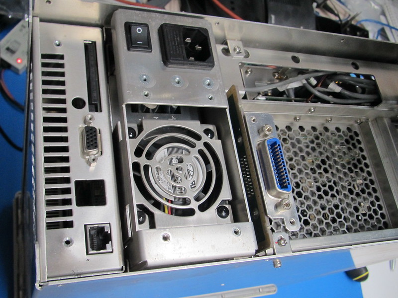
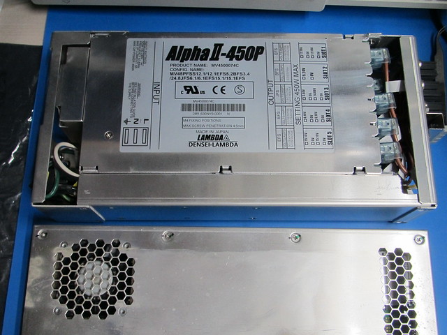
The module on the left is the PC module, the one on the right with the mains entry is the PSU.
The power supply and PC modules removed. The power supply is build around a standard power supply from Lambda.

The PC and power supply slots:
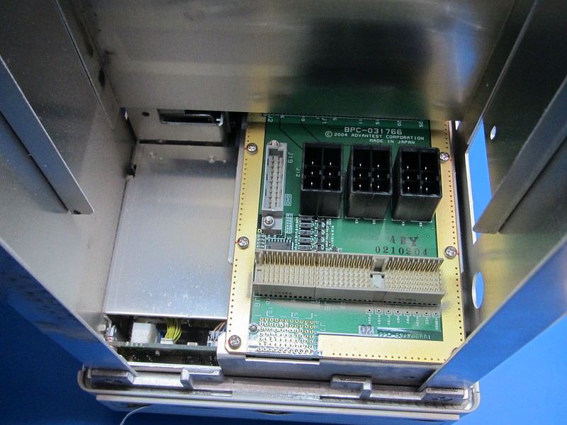
It is hard to see in the picture but there are some bodges on this board.
Inside the PC module:
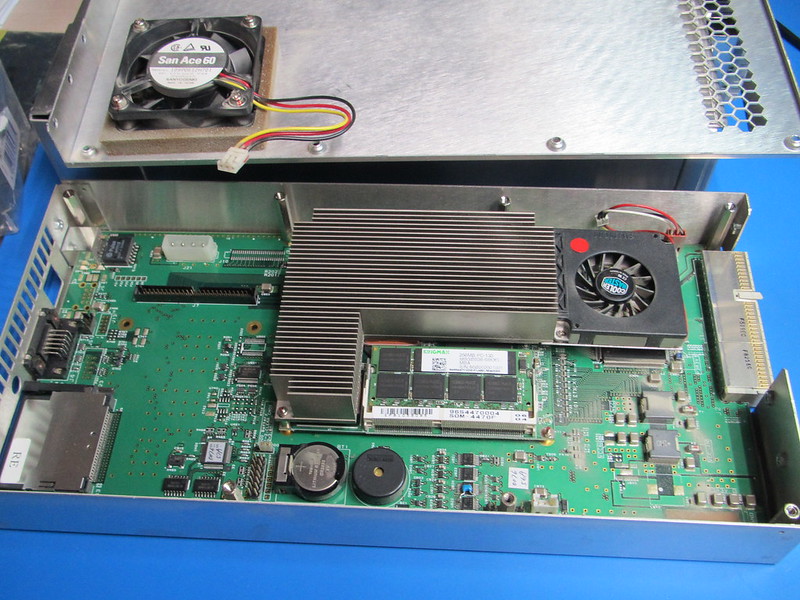
There is a fan which draws air into the module but also a fan which forces air through a large heatsink. Under the heatsink there seems to be a standard embedded PC module which is mounted onto a carrier board. On the left it looks like there is room for a standard hard drive but the (2mm pitch) connector has 50 pins instead of 44. Do I spot another botch?
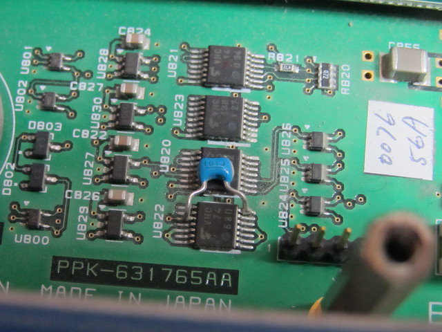
Someone must have had a very steady hand to solder a capacitor on a TSOP (0.65mm pitch) chip!
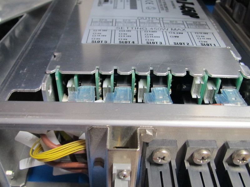
A close-up of the power supply's output section. It is pretty crammed!
Back to the problem at hand. I decided to replace the fans for the PC module and the PSU anyway. The cooler master (Sunon) fan seemed to run fine (although it makes a lot of noise). The big fan to cool the RF section also seemed fine and doesn't make much noise anyway. I tried to select fans with equal or better airflow / pressure ratings and lower noise levels. I would have liked to replace the (noisy) Cooler Master fan as well but it looks like I would need to remove the heatsink on the PC board and that probably would also disturb the heat conducting rubber.
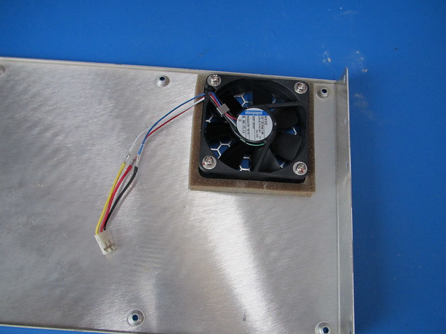
The new PC module fan. Unfortunately I had to get creative with the wiring. I didn't choose a very high end fan for the PC module even though it is a Papst:
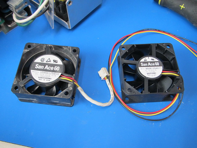
PSU fans (old and new). As a replacement I selected a fan with a slightly higher RPM and pressure rating because I already noticed the PSU gets quite warm (at 76% typical efficiency that is not a surprise!). The original fan seems to be no longer available anyway.
Instead of the original mounting clips I decided to use rubber vibration dampening fan mounts:
Time to put it back together... unfortunately the fan exchange made the problem worse! Now it always shuts down after a minute or so

After checking the tacho signals (connected a 1k Ohm pull-up from the positive supply to the tacho output) from the fans in the PC module and the big fan in the rear the problem pointed towards the PSU. So I compared the tacho signals from the old and new PSU fan. It turned out the old fan from the PSU doesn't output a tacho signal at all but commutation noise seemed to indicate the tacho should be around 150Hz. The new fan however runs faster and outputs 163Hz. As a test I decided to defeat the PSU fan failure signal and BINGO! No more 'Warning fan 4 failed' messages. Time to open up the power supply and look for obvious problems. Even though the new fan had been running for a short while in the PSU the tacho signal still worked so at least the PSU hadn't killed the tacho output.
Oh crap... that is crowded!
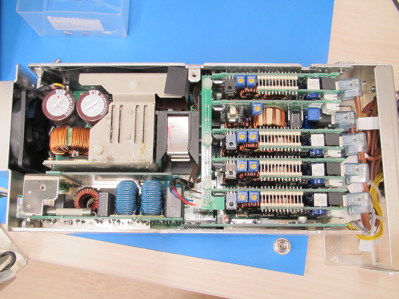
But... actually it is constructed quite cleverly. The black block (with metal clip) in the middle is the transformer. The PCB in the top left is the switching/control board, the PCB in the bottom left is the mains filter and the PCBs on the right are the output modules. At the bottom right there is also a PSU status board with an isolated power supply to provide a floating status signal. From what I have seen it is possible the remove the mains filter (which can be pulled out). After that the switching / control board can be unscrewed and pulled out to the left (the transformer is connected to the switching/control board with a connector and stays inside the PSU). However I didn't go that far! I measured whether the PSU had a short between the fan power supply and the tacho signal but that wasn't the case (measured 1.8 kOhm). I also did some checks on the PSU status board but nothing stood out. My guess is that the PSU checks whether the fan speed is within a certain margin and throws an error if it isn't. After some throught I decided to leave the fan failure signal open (defeated) since the PSU also has an over temperature protection. 'Fixing' the PSU would be a major undertaking and if it does rely on the fan operating within a small RPM range I rather do without that because things like that cause more problems than they solve.
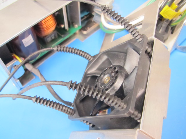
I did modify the PSU a little though. There is an aluminium frame around the PSU to make it fit and hold the various connectors. Along the side there is an open duct which could allow the PSU to suck air from the fan exhaust which would basically mean the PSU is trying to cool itself with hot air. I decided to close the duct so it can't suck in hot air from the rear. I also tied the wires coming from the PSU together to (hopefully) improve airflow.
After putting a couple of dozen screws back (fortunately there are only 2 different types) the R3477 worked as it should! It is still noisy though mostly due to the small Cooler Master fan in the PC module.


