Author Topic: An investigation about ripple current of Kunkin KP184  (Read 15863 times)

0 Members and 1 Guest are viewing this topic.

Offline doktor pytaTopic starter

  • Frequent Contributor
  • **
  • Posts: 488
  • Country: pl
An investigation about ripple current of Kunkin KP184
« on: August 02, 2020, 10:26:20 am »
I tried to check what is causing annoying current ripple in Kunkin KP184 DC electronic load.

Reference to the older thread:
https://www.eevblog.com/forum/testgear/fixing-an-manufacturer-issue-of-the-kunkin-kp184-electronic-load/

Setup:
Kunkin KP184 ver.04 with C58=10n installed by the manufacturer
Tek P6302+ AM503 current probe. Bandwidth limited to 5MHz.
The oscilloscope is AC coupled.
Linear bench power supply.
Conditions: current set on KP184 is 100mA; voltage applied 5V


Sanity check: noise of the system


Current ripple: as bought


Current ripple: without front panel


Current ripple: without front panel, without fan


Current ripple: without front panel, without fan, without 2nd MOSFET assembly


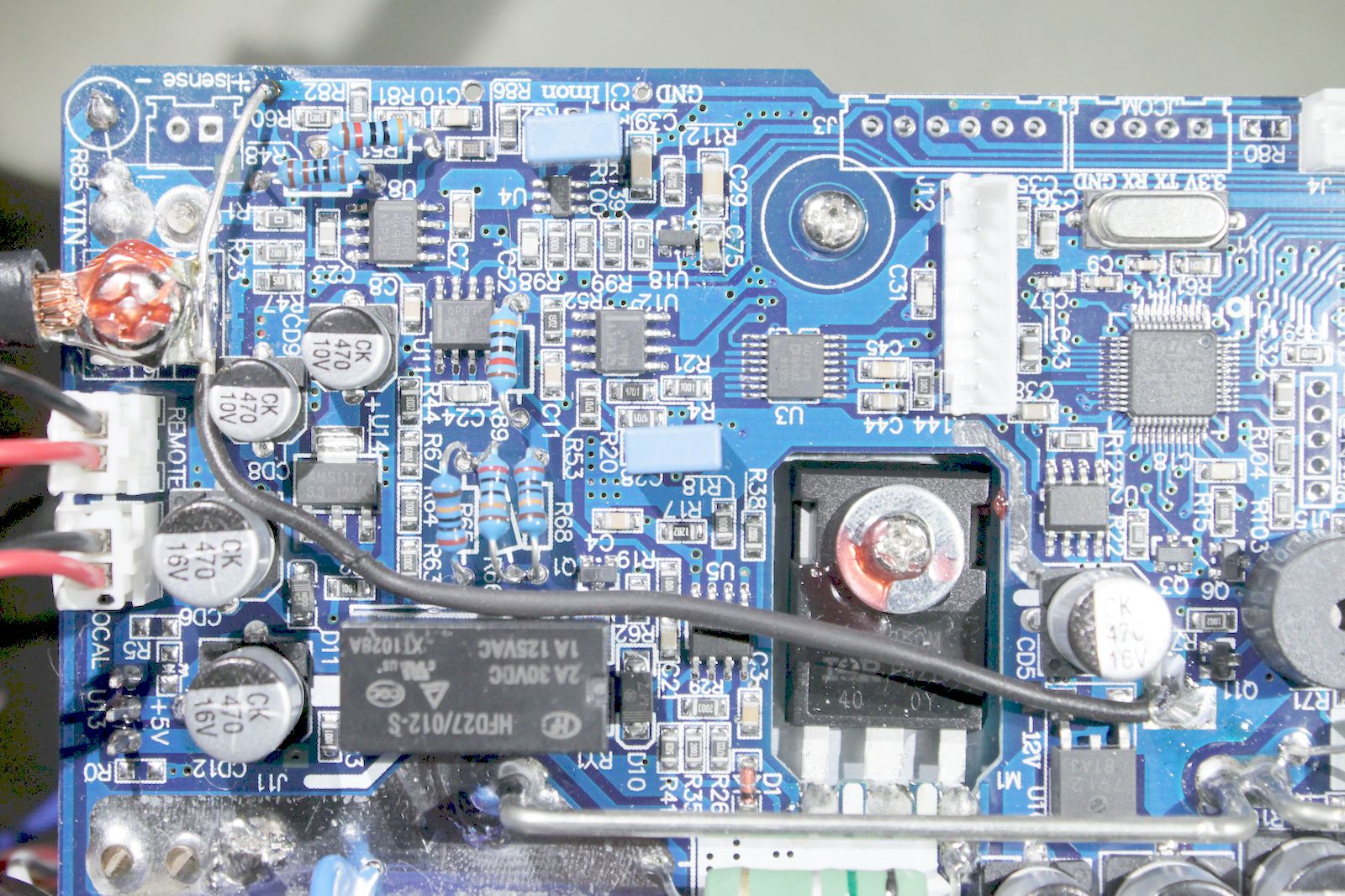
Now after staring at the PCB and some experimenting I've added a thick ground return path which looks like this


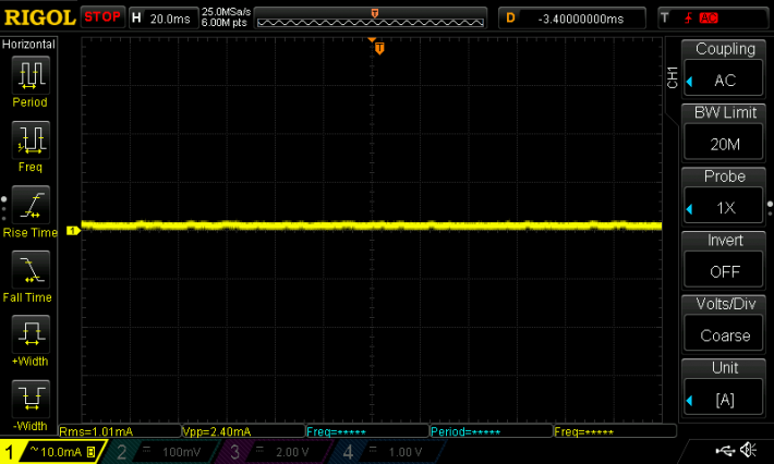
Current ripple: without front panel, without fan, without 2nd MOSFET assembly, with ground return mod


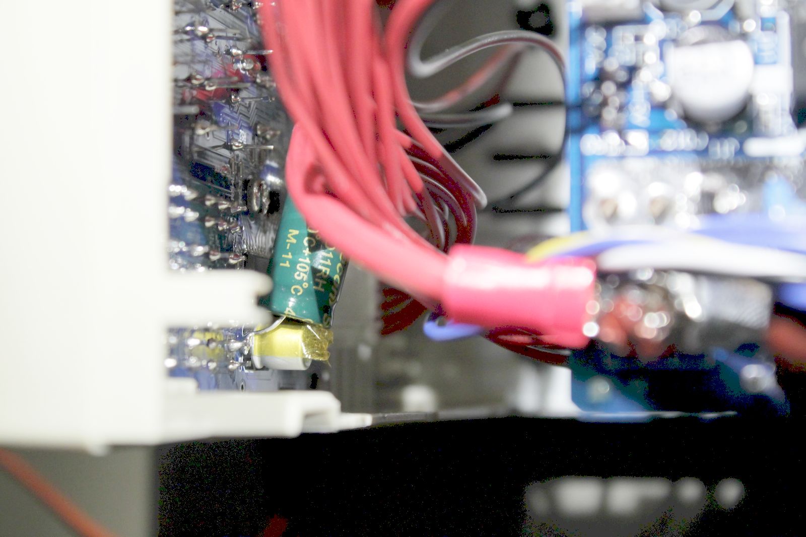
I've also added 1000uF/16V low ESR capacitor in parallel to 470uF cap on the front PCB.
Multiplexed LED display creates current spikes.
I tried to lower them by adding 10uF MLCC but without effect.
Photo of this mod below


Current ripple: with front panel C mod, without fan, without 2nd MOSFET assembly; with ground return mod


Current ripple: with front panel C mod, without fan, with 2nd MOSFET assembly; with ground return mod


Final:
Current ripple: with front panel C mod, with fan, with 2nd MOSFET assembly; with ground return mod


Conclusion:

1. due to 2 layer layout the current return path is not optimal. It can be fixed relatively easily.

2. most of the ripple comes from the fan. The rotor's magnet spins only 1cm away from current sense resistors and induces EMF in it.
It also creates HF content. I tried to add better decoupling but only electrostatic shield make things slightly better however it lowers airflow.
The fan is an integral part of the mechanical assembly.
So only solution that comes to mind is disconnecting the fan and adding another fan as far as possible in the enclosure,
however full current rating probably won't be met due to lower airflow

3. the designers didn't bothered these problems. The load is specified for Imax= 40A and even at 5A these artifacts are barely visible.

Right now I don't see any easy and cheap solution to the fan problem, so I'm staying with ground return mod and C mod applied.


« Last Edit: August 02, 2020, 10:04:25 pm by doktor pyta »
 
The following users thanked this post: thm_w, Gregg, ch_scr, duckduck, wolzlu, vladant

Offline doktor pytaTopic starter

  • Frequent Contributor
  • **
  • Posts: 488
  • Country: pl
Re: An investigation about ripple current of Kunkin KP184
« Reply #1 on: August 02, 2020, 11:26:12 am »
Additional photos + rare bottom side view.


The following users thanked this post: duckduck, vladant

Offline doktor pytaTopic starter

  • Frequent Contributor
  • **
  • Posts: 488
  • Country: pl
Re: An investigation about ripple current of Kunkin KP184
« Reply #2 on: August 04, 2020, 12:12:29 pm »
There is one interesting thing about KP184.
The crystal oscillator signal is not present.
I'm sure I'm not killing it by connecting 10:1 probe.
They are probably using internal RC oscillator.
I'd appreciate if someone confirm this.

Offline CDaniel

  • Frequent Contributor
  • **
  • Posts: 411
  • Country: ro
Re: An investigation about ripple current of Kunkin KP184
« Reply #3 on: August 05, 2020, 06:20:32 am »
If the fan is inducing that noise than the electronic is not well design and should be fixable somehow if you want and have time... this is not normal  :) Maybe missing some small caps in the current amplifier ...
« Last Edit: August 05, 2020, 06:22:31 am by CDaniel »
 

Offline doktor pytaTopic starter

  • Frequent Contributor
  • **
  • Posts: 488
  • Country: pl
Re: An investigation about ripple current of Kunkin KP184
« Reply #4 on: August 16, 2020, 09:26:25 am »
There is one possible solution to the mentioned problems: disconnect internal fan and install another fan outside enclosure, on the rear panel.

Offline AlexVlc

  • Newbie
  • Posts: 8
  • Country: es
Re: An investigation about ripple current of Kunkin KP184
« Reply #5 on: August 17, 2020, 10:43:17 am »
Hi,

My unit have noise with or without load, tested with and without the capacitor and with or without the fan, noise is present always.

1048632-0
 
The following users thanked this post: wolzlu

Offline guenthert

  • Frequent Contributor
  • **
  • Posts: 712
  • Country: de
Re: An investigation about ripple current of Kunkin KP184
« Reply #6 on: August 17, 2020, 04:26:27 pm »
Hi,

My unit have noise with or without load, tested with and without the capacitor and with or without the fan, noise is present always.

(Attachment Link)
    Is that truly the noise from the load?  I've seen such injected from other devices (here a Ethernet over Powerline adapter is the greatest offender by a large margin) into the power line.  I'd have a 2nd look with the usual suspects turned off.
 

Offline AlexVlc

  • Newbie
  • Posts: 8
  • Country: es
Re: An investigation about ripple current of Kunkin KP184
« Reply #7 on: August 17, 2020, 05:57:45 pm »
    Is that truly the noise from the load?  I've seen such injected from other devices (here a Ethernet over Powerline adapter is the greatest offender by a large margin) into the power line.  I'd have a 2nd look with the usual suspects turned off.

I mean that I have noise (around 50mV) only placing the probes in the input connector without connecting it to a load, the noise comes from the internal circuitry of the unit and persists without the fan and with or without the capacitor. I'd like to spend some time and find the problem but I don't have time.
 

Offline wolzlu

  • Newbie
  • Posts: 3
  • Country: de
Re: An investigation about ripple current of Kunkin KP184
« Reply #8 on: January 20, 2021, 02:37:54 pm »
Hi,
AlexVlc's picture shows one problem of the KP184. I have a KP184 VER:04 202007 and it also radiates a lot.
The layout of my unit is slightly different as in the photos of doktor pyta, hence the date code (202007). The buck converter of the fan and RS-232 section is too noisy. I measured about 3.8Vpp on the input side of the buck converter (internal fan not running). The measurement was not very accurate (100MHz scope and passive DIY probe), but these spikes are huge and get everywhere. Right next to the switching IC U24 (AOZ1282CI) is an unpopulated footprint for an input capacitor C34. Why?
I tied:
  • Adding C34 100n input capacitor
  • Adding short wire to reduce the unnecessary ground loop
  • Adding snubber across the Schottky diode D13 (MDD DSK34) to reduce ringing at about 120MHz
  • Adding output capacitor
Not tied:
  • Add resistor in series to bootstrap capacitor C26
  • Change diode D13 and inductor L1
  • Use external buck with proper filtering
After all I came down to 304mVpp respectively 600mVpp with fan at full speed on the input side (only power pins of fan connected).
I propose to disable U24 (via pull down) and use a linear regulator instead  ;).
 
The following users thanked this post: vladant

Online Hydron

  • Frequent Contributor
  • **
  • Posts: 987
  • Country: gb
Re: An investigation about ripple current of Kunkin KP184
« Reply #9 on: January 20, 2021, 09:54:11 pm »
I had some similar problems with my DCL6104A (same form factor to KP184, but different manufacturer, and a 500V version), thought I'd share incase it was of interest.

There were 2 ripple issues, the first is the fan next to the current shunt as seen here - is little enough (less than 10mA) that I decided to ignore it, and another is from poor layout of the power supply AC-DC rectification and regulation section.

The second issue is also similar to one you've identified here with the KP184 - with only a two layer board (quite different layout as this one) and some poor layout choices some of the 100Hz ripple interacts with the sensitive current sense signal (essentially I*R drops on the ground traces shift the current sense reference around). I managed to fix this issue with some PCB mods - see this thread for details: https://www.eevblog.com/forum/testgear/et5410-or-dcl6104-or-a-third-programmable-electronic-dc-load-in-the-budget-cat/

In terms of the fan driver, the DCL6104 does use linear regulation (BJT with a op-amp control loop), the noise from the fan is all magnetic (as mentioned) and auditory (hence my mod to reduce the speed, it was _way_ too loud at idle). I think the only switcher in the whole device is 5 or 3.3V for the front panel MCU/screen (can't remember exactly).

If I dig up any captures of the ripple I'll add them to a post in that thread, but PCB mods mostly solved it (though there weren't any HF issues from a switcher etc like seen here).
« Last Edit: January 20, 2021, 10:00:10 pm by Hydron »
 

Offline vladant

  • Newbie
  • Posts: 6
  • Country: ua
Re: An investigation about ripple current of Kunkin KP184
« Reply #10 on: May 17, 2021, 10:14:06 am »
Hi, is not that black wire on the photo bypasses current shunt ?
 

Offline graybeard

  • Frequent Contributor
  • **
  • Posts: 431
  • Country: us
  • Consulting III-V RF/mixed signal/device engineer
    • Chris Grossman
Re: An investigation about ripple current of Kunkin KP184
« Reply #11 on: May 17, 2021, 05:40:11 pm »

This video should start on the portion about load current noise.

I have seen similar noise in my Beich CH9720CU Electronic Load.   After doing a comprehensive test and tear down I believe it is due the digital feedback loop controlling the load.

In the Beich load I see two distinct almost periodic events; a faster one I think is do to the single A/D sampling the Voltage and current, and a slower one that I believe is feedback sending the current level update to the D/A driving the op-amp/MOSFET load cells.  The fact that it is not perfectly periodic is due to the regulation/measurement MCU having other duties like exchanging information with the control/GUIe interface MCU.

In the Beich load the circuit is laid out on two-sided PCBs (I assume to reduce cost) and lack controlled impedance transmission lines.   Thus coupling from the fast digital signals into the analog portion are happening as well as reflections from the fast edges of the digital signals.  I think the designer got around the reflections by giving the data time to settle before clocking into the next stage.

From your photos it appears the Kunkin load also uses two sided PCBs, so the issues may be similar.
« Last Edit: May 17, 2021, 08:50:36 pm by graybeard »
 

Offline vladant

  • Newbie
  • Posts: 6
  • Country: ua
Re: An investigation about ripple current of Kunkin KP184
« Reply #12 on: May 22, 2021, 08:40:36 pm »
I measured voltage on CD7/12 capacitors and just curious if it is a design "feature" to have 19V on 16V caps :).

So far I have found out that KP184 design has 5 major flaws:
1) +-12V supply and its ripple and noise.
2) +5V supply, its (capacitance) impact on +-12V and in turn the front LED panel impact on +5V (which is devastating).
3) FAN supply circuit and it noise.
4) Oscillation in U16 TL074 opamp #4 in Constant Voltage (CV) mode with an input resistor > 5Ohm.
5) It exists.

Resolution for flaw #:
1) Cut off +5V from main transformer by removing diodes D15/16. Now +5V rail is not powered.
2) Install another 7-12V 5W transformer to power up +5V rail (fortunately the case has plenty of room). Connect its output via diode bridge to CD12. Insert 50-100 Ohm resistor in J12 line 1 (+5V to front panel).
3) Install unpopulated C34 100nF (if you have it on your PCB version, near R25) OR install LDO with 12-13.5V output instead of existing switching DC-DC.
4) Connect input+ to R88/R9 by 1MOhm resistor and 500-1000pF capacitor (>200V) in series.
5) Cannot be helped.

Please share your results.
« Last Edit: May 22, 2021, 08:44:12 pm by vladant »
 

Offline PaWill68

  • Regular Contributor
  • *
  • Posts: 117
  • Country: ru
Re: An investigation about ripple current of Kunkin KP184
« Reply #13 on: July 20, 2021, 07:17:39 am »
I contacted the developers. C34 must be installed without fail. Rated 220nF 0805 MLCC. Can be used from position C17. When changing the fan power circuit, they forgot to install it in the first batch of products.
 
The following users thanked this post: Hamelec

Offline aristarchus

  • Regular Contributor
  • *
  • Posts: 107
  • Country: 00
Re: An investigation about ripple current of Kunkin KP184
« Reply #14 on: July 20, 2021, 01:00:57 pm »
Can this C34 position on pcb be pinpointed on a photo ?
Tried for some time to find it and it was not easy.
 

Offline PaWill68

  • Regular Contributor
  • *
  • Posts: 117
  • Country: ru
Re: An investigation about ripple current of Kunkin KP184
« Reply #15 on: July 20, 2021, 01:17:48 pm »
Can this C34 position on pcb be pinpointed on a photo ?
Tried for some time to find it and it was not easy.
 
The following users thanked this post: aristarchus

Offline PaWill68

  • Regular Contributor
  • *
  • Posts: 117
  • Country: ru
Re: An investigation about ripple current of Kunkin KP184
« Reply #16 on: July 20, 2021, 01:38:12 pm »
Friends, there is good news. KUNKIN has released a firmware update:
1) The voltage is read by reading one register, and the voltage value is obtained after smoothing and filtering, so there will be no sawtooth shape. The voltage acquisition rate before smoothing and filtering is 470SPS, and the voltage value after smoothing and filtering, the refresh rate is relatively low, it is 10SPS.
2) Instructions to set the battery discharge mode, half-current discharge is enabled and can be saved
 
The following users thanked this post: doktor pyta

Offline aristarchus

  • Regular Contributor
  • *
  • Posts: 107
  • Country: 00
Re: An investigation about ripple current of Kunkin KP184
« Reply #17 on: July 20, 2021, 01:59:06 pm »
Nice.
Thanks @PaWill68.
Though in my VER:04 KP184 there is no such cap C34, so I hope in VER:04 they have it solved.

Regarding the firmware update, is there any link to see it, download it and any instructions on how to upload/flash it in the KP184 ?
 

Offline Noy

  • Frequent Contributor
  • **
  • Posts: 361
  • Country: de
Re: An investigation about ripple current of Kunkin KP184
« Reply #18 on: July 20, 2021, 02:14:41 pm »
Hmmm, i have a V3 version here there is no C34..

I have an unmounted C60 and C58..  By the way whats now the bes case for C58? Unmounted or 10nF ??V on this place?

Is this new firmware also for V3 versions?
« Last Edit: July 20, 2021, 02:16:36 pm by Noy »
 

Offline PaWill68

  • Regular Contributor
  • *
  • Posts: 117
  • Country: ru
Re: An investigation about ripple current of Kunkin KP184
« Reply #19 on: July 20, 2021, 02:50:28 pm »
This firmware update is only for KP184 manufactured in 2019, 2020 and 2021, the model of the analog-to-digital conversion chip is AD7799. All actions are at your own peril and risk. If there are no problems, it is not recommended to update the firmware, as the changed location is not necessarily used by the user.
For questions about software bugs you can write to 64908476@qq.com
« Last Edit: July 20, 2021, 05:24:48 pm by PaWill68 »
 
The following users thanked this post: burkm, djadeski, KlausF, dl6lr

Offline PaWill68

  • Regular Contributor
  • *
  • Posts: 117
  • Country: ru
Re: An investigation about ripple current of Kunkin KP184
« Reply #20 on: July 20, 2021, 05:26:23 pm »
The problem of fan noise appeared when the design was changed later. Before the change, the power supply of the fan was not regulated, and the power supply voltage would rise to more than 17V due to the unstable grid voltage and burn the fan.
 

Offline Noy

  • Frequent Contributor
  • **
  • Posts: 361
  • Country: de
Re: An investigation about ripple current of Kunkin KP184
« Reply #21 on: July 21, 2021, 08:06:35 am »
I checked ma V3 version it has an ADS1232 so this FW is probably not for my device.
Interesting observation for the FAN Supply. Maybe i should add an TVS Diode? Or i hope that our grid voltage ist stable enough here in germany...

So still the question left should i mount 10nF with xx V rating on C58? Or should i left it unpopulated... I dismounted the original cap regarding to the earlier observations / solutions..
 

Offline PaWill68

  • Regular Contributor
  • *
  • Posts: 117
  • Country: ru
Re: An investigation about ripple current of Kunkin KP184
« Reply #22 on: July 21, 2021, 09:56:18 am »
I checked ma V3 version it has an ADS1232 so this FW is probably not for my device.
Interesting observation for the FAN Supply. Maybe i should add an TVS Diode? Or i hope that our grid voltage ist stable enough here in germany...

So still the question left should i mount 10nF with xx V rating on C58? Or should i left it unpopulated... I dismounted the original cap regarding to the earlier observations / solutions..
C58 can be omitted if C57 is present. Perhaps the scheme has changed since that time.
For ADS1232 chip, the firmware will not work and will damage the device.
 
The following users thanked this post: KlausF

Offline dl6lr

  • Frequent Contributor
  • **
  • Posts: 458
  • Country: de
Re: An investigation about ripple current of Kunkin KP184
« Reply #23 on: July 21, 2021, 10:20:50 pm »
This firmware update is only for KP184 manufactured in 2019, 2020 and 2021, the model of the analog-to-digital conversion chip is AD7799.

Updated my KP184 Board VER:04 20191111 with AD7799, previous firmware version shown was 1801. I had to make the following changes:

1. Baudrate 9600 only, tried higher settings with no success, maybe the comm settings are not effective in the bootloader
2. Device was protected, had to first erase the flash, otherwise the flashing did not succeed. It seems it tried to auto-erase the chip, but due to 3. the process was unsuccessful.
3. After Erasing the flash, had to reboot the device with pins 8+9 bridged to get the bootloader running again, then flashing was possible.

Regards, Bernd
 
The following users thanked this post: PaWill68

Offline PaWill68

  • Regular Contributor
  • *
  • Posts: 117
  • Country: ru
Re: An investigation about ripple current of Kunkin KP184
« Reply #24 on: July 22, 2021, 10:11:10 am »
Possibly related to the quality of the cable. I have RS232-USB on CH340 chip. It works at 115200 normally, but for the firmware I had to set the speed to 9600.
The manufacturer recommends cables based on the PL2303 chip. They are more stable.
 

Offline KlausF

  • Contributor
  • Posts: 30
  • Country: 00
Re: An investigation about ripple current of Kunkin KP184
« Reply #25 on: January 07, 2022, 05:56:53 pm »
Can anyone help, please. I am desparately searching for a service manual or at least a schematic of the Kunkin KP184.
 

Offline electr_peter

  • Supporter
  • ****
  • Posts: 1302
  • Country: lt
Re: An investigation about ripple current of Kunkin KP184
« Reply #26 on: February 02, 2022, 09:15:26 pm »
KP182/KP184 has additional 9th key - there is cutout on front panel (covered with a sticker) and place for a button on display PCB. Does it do anything?
 

Offline burkm

  • Regular Contributor
  • *
  • Posts: 60
  • Country: de
Re: An investigation about ripple current of Kunkin KP184
« Reply #27 on: February 17, 2022, 07:15:16 am »
This firmware update is only for KP184 manufactured in 2019, 2020 and 2021, the model of the analog-to-digital conversion chip is AD7799. All actions are at your own peril and risk. If there are no problems, it is not recommended to update the firmware, as the changed location is not necessarily used by the user.
For questions about software bugs you can write to 64908476@qq.com

Someone should post this new firmware file as a downloadable file attachment, so other recent owners of the KP184 could use this too. Would be great, if any future firmware updates would follow this way...
Fortunately there are detailed instructions how to apply the firmware within the .ZIP file and what is needed for this. I made myself a simple rs232 loopback connector and a firmware update "activator" using some parts lying around...
Most modern PCs don't have a built-in RS232 connector any more und therefor have to use an USB->RS232 adapter.
If one is going to apply the firmware update file has to be judged by the individual user, because not everyone uses all features changed or bug-fixed. Unfortunately no info are available about the changes or bug-fixes. Although the built-in microprocessor has lots more of flash memory available this is only used to a small extent. 

@electr_peter
This seems to be reserved for a front mounting placement of the power switch instead of the power switch on the back. At least some have adapted it for this...
« Last Edit: February 19, 2022, 03:23:03 pm by burkm »
 

Offline burkm

  • Regular Contributor
  • *
  • Posts: 60
  • Country: de
Re: An investigation about ripple current of Kunkin KP184
« Reply #28 on: February 18, 2022, 10:24:05 pm »
Nice.
Thanks @PaWill68.
Though in my VER:04 KP184 there is no such cap C34, so I hope in VER:04 they have it solved.

Regarding the firmware update, is there any link to see it, download it and any instructions on how to upload/flash it in the KP184 ?

All needed information including the needed flash software is within the .ZIP file containing the new Firmware. Please follow it by the word (pictures are inluded also). Just check, if the RS232 extender does speak to the chip on the KP184 mainboard, or the KP will stay in the firmware-update mode ...
« Last Edit: February 19, 2022, 03:07:36 pm by burkm »
 

Offline electr_peter

  • Supporter
  • ****
  • Posts: 1302
  • Country: lt
Re: An investigation about ripple current of Kunkin KP184
« Reply #29 on: February 19, 2022, 08:33:39 am »
@burkm, I have added mains switch (wired in series with transformer) on front panel on the bottom right near negative terminal. Additional button position I mentioned above is located between "ON", "->" and "SET" buttons, just left of rotary knob.
 

Offline burkm

  • Regular Contributor
  • *
  • Posts: 60
  • Country: de
Re: An investigation about ripple current of Kunkin KP184
« Reply #30 on: February 19, 2022, 03:13:02 pm »
I've held mine up to the light and discovered this "hidden" button position (shadow behind the front panel "mask") you mentioned too, but if it's not supported by the original firmware it won't do anything useful.
Don't have any idea, what it should be used for, may be a "reserve" for some possible extension not known at the time of designing the front panel...
« Last Edit: February 19, 2022, 03:24:29 pm by burkm »
 

Offline burkm

  • Regular Contributor
  • *
  • Posts: 60
  • Country: de
Re: An investigation about ripple current of Kunkin KP184
« Reply #31 on: February 19, 2022, 10:35:58 pm »
I checked the Kunkin web site. They got a color model similar to the KP184, the KP184C, which uses an identical front panel and has an additional key at this position (LAST).  This is probably the reason for this empty space...
 

Offline atarian

  • Newbie
  • Posts: 7
  • Country: cz
Re: An investigation about ripple current of Kunkin KP184
« Reply #32 on: February 20, 2022, 05:21:54 pm »
Hi, newbie around here. I acquired KP184 in 2020, but really have not used it until recently. As anyone here, I have quickly found out that it exhibits quite a lot of noise on input sockets, even unloaded. Unless I am reading my measurements incorrectly, I see ripple with Pk-Pk value over 1V.  Of course, this "property" defeats the whole purpose of this unit for me as I my intention was to use it benchmark PSU designs, including ripple & noise across their output range. Ergo, I would like to get rid of it, so I did a little bit of digging on my own and I have also evaluated all the tricks users here tried and reported some level of success with it.
In my case, top PCB revision is 004. Firmware has been updated to 20210720A thanks to user who posted the FW in this thread.
Other then FW update, I have tried to remove C58, or C57, played with their values too. I have tried GND wire trick too. I have put low ESR cap in parallel to front panel power rail cap. None of above helped even a bit. The ripple is still there, same levels. With and without front panel and/or fan disconnected - no change.
What I have also realized when scoping across the top PCB that basically ripple with that same signature is present all across the board, on all power rails: +5V, +3V3, +12V,-12V I mean its kind of crazy to see the 0,5V ripple on 3.3V rail, right on STM32 microcontroller pins. Same ripple signature can be also seen on input of 7805, so basically on output of rectifier bridge of 18V AC transformer output (diodes D12, D14, D16, D17). Seeing it basically on these places I am thinking - this can not be all just an induced signal from a digital section, or can it?
Either I am going crazy, or this mess can all be traced back to a transformer.
Can someone please confirm my finding on your unit?
« Last Edit: February 21, 2022, 09:39:40 am by atarian »
 

Offline dophuc

  • Contributor
  • Posts: 38
  • Country: vn
Re: An investigation about ripple current of Kunkin KP184
« Reply #33 on: February 20, 2022, 06:59:46 pm »
I measured the noise at the KP184 input jack (no load). My Kp184 is the 2020 version, nothing has changed since I bought it.

« Last Edit: February 20, 2022, 07:05:46 pm by dophuc »
 

Offline electr_peter

  • Supporter
  • ****
  • Posts: 1302
  • Country: lt
Re: An investigation about ripple current of Kunkin KP184
« Reply #34 on: February 20, 2022, 09:06:39 pm »
@atarian, what do you measure when scope probe is on output connector, but DC load is turned-off on the back (but still connected to mains)?
 

Offline atarian

  • Newbie
  • Posts: 7
  • Country: cz
Re: An investigation about ripple current of Kunkin KP184
« Reply #35 on: February 21, 2022, 08:43:07 am »
Here are some more grabs. Probe connected onto the VIN+ and VIN- screw terminals on top board this time. Scope set to DC coupling now to be see if any DC voltage is present. Like this, I have seen massive swing down to -3VDC with rise time about 0,8s and drop time about 5s. Just like coil kick back, only there is no coil anywhere as far as I can see? Except for the transformer...
Anyway, here you are:
DC coupling, 1V and 200us /div

« Last Edit: February 21, 2022, 08:46:48 am by atarian »
 

Offline atarian

  • Newbie
  • Posts: 7
  • Country: cz
Re: An investigation about ripple current of Kunkin KP184
« Reply #36 on: February 21, 2022, 08:47:40 am »
In greater details:
DC coupling, 200mV and 400ns /div
 

Offline atarian

  • Newbie
  • Posts: 7
  • Country: cz
Re: An investigation about ripple current of Kunkin KP184
« Reply #37 on: February 21, 2022, 08:51:40 am »
AC mains switch state change events:
 

Offline atarian

  • Newbie
  • Posts: 7
  • Country: cz
Re: An investigation about ripple current of Kunkin KP184
« Reply #38 on: February 21, 2022, 09:24:28 am »
AC output on transformer looks good enough tho. Almost perfect 50Hz sine, no oscillations. Something must have been feeding this 5MHz noise into the 16V DC power rail then. As far as I can see there is only 7805 linear 5V regulator and some SOT23-6 packaging chip hooked up there (U24). I think I have my suspect.

EDIT: U24 seems to be some kind of switched mode power/PWM fan speed controller. With U24 temporarily removed from PCB, all ripple on DC power rails and output is gone.
G.O.N.E.

All I am seeing is just white noise with amplitude of around 15mV (my oscilloscope/probes can not do any better anyway). Naturally, heatsink cooling fan is out of order now and the question is how to hook it up again. Does anyone see any better solution then to move it entirely onto separate board with separate power supply?
Can anyone please identify the chip so that we get at least a datasheet with design recommendations? Maybe Kunkin just fed up something in its implementation.
« Last Edit: February 21, 2022, 09:55:52 am by atarian »
 

Offline atarian

  • Newbie
  • Posts: 7
  • Country: cz
Re: An investigation about ripple current of Kunkin KP184
« Reply #39 on: February 21, 2022, 01:00:29 pm »
After all, it will not be that hard task: U24 is simple switching mode regulator with very poor parameters. Yes, it cripples input "by design":
http://aosmd.com/res/data_sheets/AOZ1282CI.pdf


Offline burkm

  • Regular Contributor
  • *
  • Posts: 60
  • Country: de
Re: An investigation about ripple current of Kunkin KP184
« Reply #40 on: February 21, 2022, 06:26:29 pm »
To check, if that chip is really responsible for the measured and detected visible noise floor, one should look, if the application notes (spec sheet) for that chip have been observed in detail by the chosen PCB design (layout) and its components.
This will determine, if it really "cripples input by design"
 

Offline burkm

  • Regular Contributor
  • *
  • Posts: 60
  • Country: de
Re: An investigation about ripple current of Kunkin KP184
« Reply #41 on: February 21, 2022, 06:29:58 pm »
But there is still another "problem": instability of the electronic load in combination with specific power supplies as determined by some fluctuating output.
Any idea, how to get around it and what has to be done because of this...
 

Offline electr_peter

  • Supporter
  • ****
  • Posts: 1302
  • Country: lt
Re: An investigation about ripple current of Kunkin KP184
« Reply #42 on: February 21, 2022, 07:18:27 pm »
Noise in DC load can be mitigated if the source is known (mentioned by posters above in KP184 case).

Instability with active DC load can be broadly spitted in few categories:
  • DC supply just cannot handle the load or load changes and goes crazy. DC load is not at fault, any other DC load with same parameters would cause same issue OR
  • DC load just cannot maintain the load and is unstable by design. DC supply is not at fault OR
  • DC supply and DC load in combination become unstable. This is because control loops in DC supply and DC load fight against each other, creating feedback loop with wild oscillating results.
Combination is the most likely cause, as others are easier to solve. Actual strategies to limit instability:
  • from DC load side - do nothing and continue to "maintain" load (most DC loads, including KP184)
  • from DC load side - admit failure, i.e., show that oscillation occurs via "Unregulated load" error message and/or
    turn off DC load
  • manually change DC load and/or DC supply parameters (loop speed) to reduce oscillation capability. Only some DC loads and DC supplies are capable of this
  • modify external circuitry between DC load/DC supply if you have idea what is causing it
In general, Mr Murphy ensures that it is possible to create unfavorable conditions for any DC load. EEVblog has several videos with DC loads oscillating, especially in CR mode.
« Last Edit: February 21, 2022, 07:20:25 pm by electr_peter »
 

Offline atarian

  • Newbie
  • Posts: 7
  • Country: cz
Re: An investigation about ripple current of Kunkin KP184
« Reply #43 on: February 21, 2022, 07:41:49 pm »
>>To check, if that chip is really responsible for the measured and detected visible noise floor, one should look, if the application notes (spec sheet) for that chip have been observed in detail by the chosen PCB design (layout) and its components.
This will determine, if it really "cripples input by design"

I was referring to their own characteristics published in linked datasheet, namely IN voltage waveforms. And they of course represent best case scenario of flawless implementation "by a book".
 

Offline burkm

  • Regular Contributor
  • *
  • Posts: 60
  • Country: de
Re: An investigation about ripple current of Kunkin KP184
« Reply #44 on: February 21, 2022, 08:56:06 pm »
Noise in DC load can be mitigated if the source is known (mentioned by posters above in KP184 case).

Instability with active DC load can be broadly spitted in few categories:
  • DC supply just cannot handle the load or load changes and goes crazy. DC load is not at fault, any other DC load with same parameters would cause same issue OR
  • DC load just cannot maintain the load and is unstable by design. DC supply is not at fault OR
  • DC supply and DC load in combination become unstable. This is because control loops in DC supply and DC load fight against each other, creating feedback loop with wild oscillating results.
Combination is the most likely cause, as others are easier to solve. Actual strategies to limit instability:
  • from DC load side - do nothing and continue to "maintain" load (most DC loads, including KP184)
  • from DC load side - admit failure, i.e., show that oscillation occurs via "Unregulated load" error message and/or
    turn off DC load
  • manually change DC load and/or DC supply parameters (loop speed) to reduce oscillation capability. Only some DC loads and DC supplies are capable of this
  • modify external circuitry between DC load/DC supply if you have idea what is causing it
In general, Mr Murphy ensures that it is possible to create unfavorable conditions for any DC load. EEVblog has several videos with DC loads oscillating, especially in CR mode.

Any idea, what can be done about this ???
I got this same problem in combination KP184 and BK 9174 power supply. The BK 9174 was quite expensive and it goes into overvoltage or overcurrent protection below the range extremes quite often, when this happens...
« Last Edit: February 22, 2022, 01:57:25 pm by burkm »
 

Offline electr_peter

  • Supporter
  • ****
  • Posts: 1302
  • Country: lt
Re: An investigation about ripple current of Kunkin KP184
« Reply #45 on: February 22, 2022, 07:50:56 am »
Any idea, what can be done about this ???
I got this same problem in combination KP184 and BK 9174 power supply. The BK 9174 was quite expensive and it goes into overvoltage or overcurrent protection below the range extremes, when this happens...
Potential solution requires to know more details. Under what conditions instability occurs? What is the connection setup with leads? Which load mode do you use? Which instrument is turned on first? Can you increase load gradually?
 

Offline burkm

  • Regular Contributor
  • *
  • Posts: 60
  • Country: de
Re: An investigation about ripple current of Kunkin KP184
« Reply #46 on: February 23, 2022, 06:46:05 pm »
Friends, there is good news. KUNKIN has released a firmware update:
1) The voltage is read by reading one register, and the voltage value is obtained after smoothing and filtering, so there will be no sawtooth shape. The voltage acquisition rate before smoothing and filtering is 470SPS, and the voltage value after smoothing and filtering, the refresh rate is relatively low, it is 10SPS.
2) Instructions to set the battery discharge mode, half-current discharge is enabled and can be saved

I got a new KP184 a few days ago and it seemed to work just fine (original firmware version was probably the predecessor "2020 something").
After the firmware update (see above) the KP184 was functioning "OK" for several hours, but now, in the midst of a continous 6VDC / 1A load measurement the voltage display (plus the corresponding wattage display) stopped working, just showing now "all zeros", no matter what signal it was currently fed.

I haven't had  any success in finding the cause even after intense searching, although I tried a different (proven) lab power supply from BK Precision I got in my "lab" instead of the Rigol DP832A, different input voltages and amperage profiles, switching voltage sensing from "remote" to "local", a reset to factory default parameters, disconnecting it from the mains, turning it off and on again etc. etc. etc...
Measurement gear connected directly to the output of the power supply are prove of a functional power supply by either unit. Voltages etc. are continously monitored by two Rigol Lab DMMs (6 1/2 and 5 1/2 digits resolution) Everything I could think of to remedy the problem I already tried. I inspected all the PCBs inside the unit without any success and found no hint about any visible cause for the failure. Main board version is "5 (202012)" including the daughter board, display board version is "3". The included test certificate is dated October 20th 2021. Could be a firmware "thing", because your firmware update notes for the new firmware seem to point suspiciously into that direction (=>voltage handling) ?

I don't know, what is going to happen, if I am trying to reinstall the firmware -again- , which is on the KP184 already. Reason: I don't want to be left with a non-functional unit in an incomplete firmware update state, if it's not possible to reinstall the firmware version over the existing one, because i might return the disfunct device. This seems to be my last resort before returning it to the seller...
Otherwise if this is not possible, I would try to reinstall the previous firmware version. Do You have it also ?

If nothing helps, I will contact the seller, being on the verge of returning the KP184, if the problem can't be resolved on my side...

Ps.: Is that new firmware an official release of the manufacturer (Kunkin) or is it "homebrew" ?
If it is "offical" could you check, if an update for that firmware is avilable, may be a "bug fix" ??

« Last Edit: February 26, 2022, 09:26:04 am by burkm »
 

Offline burkm

  • Regular Contributor
  • *
  • Posts: 60
  • Country: de
Re: An investigation about ripple current of Kunkin KP184
« Reply #47 on: February 26, 2022, 09:30:23 am »
I tried to message directly the user "PaWill68" several days ago, but he did not respond, neither to the post here nor to my PM message adressing him directly.
Several days have passed since my post dated February 23rd 2022 but no answer from PaWill68 yet... Well...
« Last Edit: March 03, 2022, 09:09:58 pm by burkm »
 

Offline burkm

  • Regular Contributor
  • *
  • Posts: 60
  • Country: de
Re: An investigation about ripple current of Kunkin KP184
« Reply #48 on: March 10, 2022, 10:32:19 am »
The seller of the KP184 sent me a (free) return label in the meantime.

After a recent clean-up of my (messy  :)) "hobby"-room (inluding moving around and lifting up the KP184 several times) and just before returning my non-functional unit I turned it on "a last time" just to casually check, that everything was as before.
To my surprise the voltage and wattage display seemed to be showing real voltages and wattages again, not just "zeros" as before. Now I'm thinking of a "cold" solder joint, loose connection or something similar etc., which might have caused those problems.
Some have already posted about manufacturing problems in this respect...
I contacted the seller - again - and he gave the permission to open up the sealed unit's case to look after those problems and eventually have them fixed right away. If I will find anything I will report back...
« Last Edit: March 10, 2022, 10:33:52 am by burkm »
 

Offline dirtcooker

  • Contributor
  • Posts: 48
  • Country: us
Re: An investigation about ripple current of Kunkin KP184
« Reply #49 on: March 21, 2022, 05:24:02 pm »
In greater details:
DC coupling, 200mV and 400ns /div

I have 2 kp184 units, and can confirm noise coming from it at around 500khz. I purchased this one Oct 2020, and made the following mods: removed C58 (10 nf on v4 motherboard) to reduce instability at 1A current sinking, removed paint under cover screws, applied kapton to rear screws (which are connected to + output), replaced binding posts. old ones > 4mm inside dimension reducing contact with banana plug.
A 10nf cap across the binding posts reduces the noise somewhat. Note that I live in the city, and there is a lot of RF noise from nearby radio stations, unfortunately, which you can see on my scope.
« Last Edit: March 21, 2022, 05:28:02 pm by dirtcooker »
 

Offline tautech

  • Super Contributor
  • ***
  • Posts: 28371
  • Country: nz
  • Taupaki Technologies Ltd. Siglent Distributor NZ.
    • Taupaki Technologies Ltd.
Re: An investigation about ripple current of Kunkin KP184
« Reply #50 on: March 21, 2022, 07:46:43 pm »
Note that I live in the city, and there is a lot of RF noise from nearby radio stations, unfortunately, which you can see on my scope.
Turn your 20 MHz BW limiter on for these types of measurements.  ;)
Avid Rabid Hobbyist
Siglent Youtube channel: https://www.youtube.com/@SiglentVideo/videos
 

Offline PaWill68

  • Regular Contributor
  • *
  • Posts: 117
  • Country: ru
Re: An investigation about ripple current of Kunkin KP184
« Reply #51 on: April 29, 2022, 08:18:50 am »
Sorry, I haven't been on the forum for months.
Insider information from KUNKIN:
Production of a new hardware version has begun, where the main changes are in two places.
1) Stabilization of the fan supply voltage from LM317.
2) Improved voltage and current measurement accuracy, temperature drift is much smaller.
3) The new version of the MCU is based on ARM-CORTEX-M3 GD32F130C8T6, which greatly increased the performance and protection response.
The new software is not compatible.
I don't have more detailed information.
« Last Edit: April 29, 2022, 08:20:26 am by PaWill68 »
 

Offline burkm

  • Regular Contributor
  • *
  • Posts: 60
  • Country: de
Re: An investigation about ripple current of Kunkin KP184
« Reply #52 on: April 29, 2022, 08:25:11 am »
I resolved some of the problems mentioned by rerouting the fan cables and resoldering some suspicious solder-connections. My mainboard version was V5.
Was actually going to order a 2nd one after this, but I am now waiting for the new hard- and firmware version announced in the post before...
« Last Edit: April 29, 2022, 08:27:05 am by burkm »
 

Offline burkm

  • Regular Contributor
  • *
  • Posts: 60
  • Country: de
Re: An investigation about ripple current of Kunkin KP184
« Reply #53 on: November 11, 2022, 08:16:42 am »
Anyone seen anything of the KP184 version mentionend before ? I checked ebay i.e., but I don't find any mention of a new hardware version or else.
 

Offline seronday

  • Regular Contributor
  • *
  • Posts: 93
  • Country: au
Re: An investigation about ripple current of Kunkin KP184
« Reply #54 on: November 11, 2022, 09:58:12 pm »
I recently obtained a KP184 which has a main board ver 06,  fitted with an LM317 to regulate the fan supply and a GD32F130C8T6 MCU

Regards.
 

Offline burkm

  • Regular Contributor
  • *
  • Posts: 60
  • Country: de
Re: An investigation about ripple current of Kunkin KP184
« Reply #55 on: December 12, 2022, 07:20:21 am »
Whom did You get it from ? Couldn't find any mentioning anywhere about the new version / new hardware ?
 

Offline seronday

  • Regular Contributor
  • *
  • Posts: 93
  • Country: au
Re: An investigation about ripple current of Kunkin KP184
« Reply #56 on: December 12, 2022, 10:30:43 am »
I purchased the KP184 from this Ebay seller:-    tooldealers.

https://www.ebay.com.au/itm/263281377583?hash=item3d4ccb012f:g:nqwAAOSw-qpg9R2~

The KP184 has a label on the rear showing a build date of September 2022

Regards.
 

Offline electr_peter

  • Supporter
  • ****
  • Posts: 1302
  • Country: lt
Re: An investigation about ripple current of Kunkin KP184
« Reply #57 on: December 12, 2022, 02:12:57 pm »
Banggood has started offering KP184 recently again. BG only ships in batches till stock lasts. Before BG sold KP184 model till batch lasted.
Likely BG have the newest version, but you never can be certain for sure.
 

Offline JimBeam

  • Contributor
  • Posts: 34
  • Country: de
Re: An investigation about ripple current of Kunkin KP184
« Reply #58 on: January 28, 2023, 03:02:30 pm »
Hi everyone,

I bought a KP184 from eBay and the mainboard is the new Version 06 with the GD32F MCU. It was sold as new but arrived without any accessories - no cables, not even the original package, just wrapped in bubble foil... It was manufactured - according to the sticker - on 2022-09-14.

First tests were OK, I was just wondering why the fan would not spin up after sinking 300W for a minute and the case already becoming hot.

Then I tried to connect it to the PC without any success - and I tried a lot of adapters, cables, USB-to-RS232 converters, etc.

Finally I opened up the device, as I wanted to change the connectors and install a power switch on the front anyways. After some poking around I found that neither the fan nor the MAX232 for the serial port got any power. Looking for the fault I found the LM317T to be defective, between the ADJ and OUT pins where only 60 Ohms. After replacing the LM317T and also relocating the LM7805 hanging under the mainboard to the heatsink just beside the LM317T, I was able to connect the unit to the PC and - bingo - the fan now ran too.

Being euphorized I went ahead and installed the new 2128 firmware, but while the upload was still running my heart stopped beating for a moment, wasn't there something with the MCU being a GD32 instead of the "old" STM32? :scared: For a moment I was tempted to stop the upload but didn't as it already had erased the flash and was at about 30% upload, so I let it finish.

After the upload was finished the fan went to hyperspeed, the display flickered but it showed the 2128 version - for about 15s - then the normal screen appered (still flickering) and I could even use the menu, I was able to enter a new current value in CC mode too, but when I pressed SET, the unit froze.  |O

Now I had a half-bricked device, with fortunately the bootloader still intact. Of course I tried to upload again, in the hope something went wrong the first time, but nope...

Well, that's the current state. So my question to PaWill68: did you already have a source for a firmware for the Ver.06 mainboard? I did not note the version the unit had before I bricked it, but it was something like 2021.

Andreas
« Last Edit: January 28, 2023, 03:08:50 pm by JimBeam »
 

Offline JimBeam

  • Contributor
  • Posts: 34
  • Country: de
Re: An investigation about ripple current of Kunkin KP184
« Reply #59 on: February 02, 2023, 03:25:36 pm »
In reply to my own posting:

I contacted 64908476@qq.com (mentioned in msg#27 of this thread) , who sent me the firmware  :-+
With permission of 64908476 (I don't know his/her real name...) I attach it to this post, for anyone who might need it, it's V2201 for the Ver.06 mainboard with GD32F processor.

And he/she wrote further, that there is already a Ver.07 on the way:
Quote
However, the current PCB version is 07, buzzer sound changed to chord mode, optimize fast over-power protection function, and voltage and current temperature drift are further optimized.
In addition, the problem of small current (<100mA) with power frequency ripple (100Hz) in CC/CR/CW mode has been improved (affected by PCB wiring has not been completely solved).
« Last Edit: February 02, 2023, 03:30:14 pm by JimBeam »
 

Offline burkm

  • Regular Contributor
  • *
  • Posts: 60
  • Country: de
Re: An investigation about ripple current of Kunkin KP184
« Reply #60 on: April 02, 2023, 09:07:36 am »
Any further News on the latest versions of KP184 ?
 

Offline torch

  • Frequent Contributor
  • **
  • Posts: 397
Re: An investigation about ripple current of Kunkin KP184
« Reply #61 on: August 02, 2023, 06:31:45 am »
I just got one today. Build date 2023/06/29. Main board version 7, dated 2022/11/??. Bottom board is version 6, dated 2022/12/12.

Very little noise compared to earlier reports. A 15uS ripple of 9-10mv at 400Hz.

Other observations: I like the sound. Instead of the standard beeping, it gives a soft chime on button presses -- and has different chimes for up/down, etc. They seem to have fixed the oversize banana plug issue -- mine all fit fine. The displayed values seem to all be in spec - very close when compared to a Fluke 175, a VC8145 and the Korad PS display. The large diameter wires all seemed adequately soldered.

Other noted problems still exist: the transformer mounting bolts were just finger tight so the transformer could wobble. The case screw holes still need to be scraped. The rear panel heat shrink screws are still connected to DC+. There's still no indication if the voltage sense source is internal or external. And while overall the internals look quite neat and professional, I found a blob of spilled solder lightly stuck to the the main board, between the DC+ connection and a little 3.3v regulator.  Mine came with a European power cord (I'm on teh other side of the Atlantic) and did not come with an RS232 cable. Nor did it come with any software.

But overall, I'm pleased. At that price point it's a pretty darn solid piece of kit.
 

Offline Everbrave

  • Contributor
  • Posts: 25
  • Country: ch
Re: An investigation about ripple current of Kunkin KP184
« Reply #62 on: August 03, 2023, 10:14:49 pm »
I just got one today. Build date 2023/06/29. Main board version 7, dated 2022/11/??. Bottom board is version 6, dated 2022/12/12.

Very little noise compared to earlier reports. A 15uS ripple of 9-10mv at 400Hz.

Other observations: I like the sound. Instead of the standard beeping, it gives a soft chime on button presses -- and has different chimes for up/down, etc. They seem to have fixed the oversize banana plug issue -- mine all fit fine. The displayed values seem to all be in spec - very close when compared to a Fluke 175, a VC8145 and the Korad PS display. The large diameter wires all seemed adequately soldered.

Other noted problems still exist: the transformer mounting bolts were just finger tight so the transformer could wobble. The case screw holes still need to be scraped. The rear panel heat shrink screws are still connected to DC+. There's still no indication if the voltage sense source is internal or external. And while overall the internals look quite neat and professional, I found a blob of spilled solder lightly stuck to the the main board, between the DC+ connection and a little 3.3v regulator.  Mine came with a European power cord (I'm on teh other side of the Atlantic) and did not come with an RS232 cable. Nor did it come with any software.

But overall, I'm pleased. At that price point it's a pretty darn solid piece of kit.
Did you watch the change of the ripple value as the load current is changed?
Do you mind telling where you bought it from in Europe? Price if possible ;)
Firmware version?
MOSFET type number?
Perhaps some photos of the new Board?
Thanks
« Last Edit: August 03, 2023, 10:28:47 pm by Everbrave »
 

Offline Everbrave

  • Contributor
  • Posts: 25
  • Country: ch
Re: An investigation about ripple current of Kunkin KP184
« Reply #63 on: August 04, 2023, 12:39:20 pm »
I have a V6 Board and I can, interestingly, report that the ripple value at lower load current is higher than at higher load current!
Here are some pics …
At 100mA and 1.1A respectively (around 42V) …

EDIT: I can imagine that the ripple (noise) is inherent in the current control loop (bandwidth) since at lower currents the S/N ratio is lower.
« Last Edit: August 06, 2023, 10:18:40 am by Everbrave »
 

Offline torch

  • Frequent Contributor
  • **
  • Posts: 397
Re: An investigation about ripple current of Kunkin KP184
« Reply #64 on: August 14, 2023, 01:10:16 am »

Did you watch the change of the ripple value as the load current is changed?
Do you mind telling where you bought it from in Europe? Price if possible ;)
Firmware version?
MOSFET type number?
Perhaps some photos of the new Board?
Thanks
Sorry I've taken so long to get back to you, I've been too busy using it to take it apart again until today.

Ok, so change in ripple current. Judge for yourself. Power source is Korad KA3305P:

5v 1a


Huh, that's weird. The scope is showing a negative value for Delta-Y. Is that even mathematically possible? 

5v 5a


15v 3a


15v 5a


31v 1a


31v 3a


31v 5a


I'll get to the guts in the next post...

EDIT: I forgot to mention. Strange things happen if I inadvertently set the Kunkin draw to exceed the Korad CC limit! The two seem to fall into some sort of race condition thereafter with each fighting the other over control of the current. Wild voltage swings of well over 100mV can result. One must shut them both off and restart with the Korad set to supply more than the Kunkin is trying to draw.
« Last Edit: August 14, 2023, 01:49:44 am by torch »
 

Offline torch

  • Frequent Contributor
  • **
  • Posts: 397
Re: An investigation about ripple current of Kunkin KP184
« Reply #65 on: August 14, 2023, 01:23:22 am »
Ok, circuit board porn:

Rear half of the top board


Front half:


Can't really make it out in the pic, but it says IRFP250M on the chip:


Top board revision:


Bottom board revision:


Front half of the bottom board, as near as I can photograph without further disassembly:


Rear half of same:


The rear board is only 1/2 width anyway. Chips bolted direct to the heat sink:


And the little switch board attached to the rear panel. This becomes important in the next post.


Offline torch

  • Frequent Contributor
  • **
  • Posts: 397
Re: An investigation about ripple current of Kunkin KP184
« Reply #66 on: August 14, 2023, 01:41:42 am »
Like I said, I've been using it. Great addition to the bench, wish I had one years ago. But. That reaching around to the power switch is getting old fast. Time to do something about it:

As others have noted, the front panel is cast to hold something on the bottom right. I don't know if it was for a power switch or a USB port, but I thought this little guy would fit:


As it turns out, 13mm was perfect. 7mm was a hair too wide. I thinned the front panel plastic a hair with a Dremel tool, until it popped in snug and secure. After drilling a hole for the toggle, of course!


I had hoped to interrupt the supply to the transformer. However, they used a centre tap transformer, switched by the 120/140 switch at the rear. As I am on 120v mains, and as there is no way a wider switch would fit in that tiny pocket, I had to go for the point were Line met board. The socket's tab was actually just soldered to the side of that rear board so it was easy to desolder, bend slightly, solder one wire to the tab and the second to the board. Heat shrink all 'round, of course!


And here we go. No more reach-arounds for me!!!  ;D


Oh, and as for your question about price: I'm not in Europe. I bought one off Banggood. About CDN$250 all in after shipping, insurance and taxes.
 

Offline Everbrave

  • Contributor
  • Posts: 25
  • Country: ch
Re: An investigation about ripple current of Kunkin KP184
« Reply #67 on: August 17, 2023, 08:48:48 am »
Thanks a lot for the great effort. However, the resolution of the pics is too low to read the MOSFET Typ Nr., do you mind writing it down?
Also, the Firmware version would be interesting.
As for the ripple form and magnitude, it’s quite different from my board V6. I can’t explain without schematics, which I couldn’t find anywhere.
 

Offline Hamelec

  • Regular Contributor
  • *
  • Posts: 154
  • Country: de
Re: An investigation about ripple current of Kunkin KP184
« Reply #68 on: August 17, 2023, 09:51:06 am »
see above:
"Can't really make it out in the pic, but it says IRFP250M on the chip:"
 

Offline torch

  • Frequent Contributor
  • **
  • Posts: 397
Re: An investigation about ripple current of Kunkin KP184
« Reply #69 on: August 17, 2023, 10:54:53 am »
Thanks a lot for the great effort. However, the resolution of the pics is too low to read the MOSFET Typ Nr., do you mind writing it down?
Also, the Firmware version would be interesting.
As for the ripple form and magnitude, it’s quite different from my board V6. I can’t explain without schematics, which I couldn’t find anywhere.

As noted, the Mosfets claim to be IRFP250M. They look pretty convincing, I don't suspect counterfeits, but who knows these days?

The second line on boot is "2303" I assume that's the firmware version?
 

Offline Everbrave

  • Contributor
  • Posts: 25
  • Country: ch
Re: An investigation about ripple current of Kunkin KP184
« Reply #70 on: August 17, 2023, 03:55:38 pm »
Thanks a lot for the great effort. However, the resolution of the pics is too low to read the MOSFET Typ Nr., do you mind writing it down?
Also, the Firmware version would be interesting.
As for the ripple form and magnitude, it’s quite different from my board V6. I can’t explain without schematics, which I couldn’t find anywhere.

As noted, the Mosfets claim to be IRFP250M. They look pretty convincing, I don't suspect counterfeits, but who knows these days?

The second line on boot is "2303" I assume that's the firmware version?
Reverting to the older IRFP250M  from the newer IRFP264 (in V6 board) is a bit astonishing. I compared the specs thoroughly but can't think of a reason!
If I would care to have a max. junction temp of 175Deg Celsius, I would rather choose IRFP260N.
I wounder if we, V6-Board owner, can upgrade to FW2303; any ideas?
Thanks
« Last Edit: August 17, 2023, 05:06:38 pm by Everbrave »
 

Offline torch

  • Frequent Contributor
  • **
  • Posts: 397
Re: An investigation about ripple current of Kunkin KP184
« Reply #71 on: August 17, 2023, 05:09:01 pm »
\
Reverting to the older IRFP250M  from the newer IRFP264 (in V6 board) is a bit astonishing. I compared the specs thoroughly but can't think of a reason!
It looks like the IRFP250 has faster rise/fall times, so maybe helps control ripple. I'd like to think it's something like that, but honestly, at this price point it probably has more to do with what was on sale that week.

I still don't understand why they used the wrong DB9 connector. Or if male connectors were on sale, why they didn't at least wire it for a null modem cable instead of straight-through?  ??? Mine did not come with the cable, so I had to go hunt down a cable AND a gender changer.
« Last Edit: August 17, 2023, 05:13:22 pm by torch »
 

Offline Hamelec

  • Regular Contributor
  • *
  • Posts: 154
  • Country: de
Re: An investigation about ripple current of Kunkin KP184
« Reply #72 on: August 17, 2023, 05:14:01 pm »
RS232 was always weird over the last decades   |O
 

Offline Everbrave

  • Contributor
  • Posts: 25
  • Country: ch
Re: An investigation about ripple current of Kunkin KP184
« Reply #73 on: August 17, 2023, 09:58:53 pm »
\
Reverting to the older IRFP250M  from the newer IRFP264 (in V6 board) is a bit astonishing. I compared the specs thoroughly but can't think of a reason!
It looks like the IRFP250 has faster rise/fall times, so maybe helps control ripple. I'd like to think it's something like that, but honestly, at this price point it probably has more to do with what was on sale that week.

I still don't understand why they used the wrong DB9 connector. Or if male connectors were on sale, why they didn't at least wire it for a null modem cable instead of straight-through?  ??? Mine did not come with the cable, so I had to go hunt down a cable AND a gender changer.

IRFP250M has less capacitances in general. This could also be the reason to the high frequency contents (ringing) in the ripple; but again, I am only guessing here.
EDIT: I looked-up the prices: IRFP250N is around 1.5USD, IRFP264 is around 5.3USD
« Last Edit: August 20, 2023, 08:28:16 pm by Everbrave »
 

Offline torch

  • Frequent Contributor
  • **
  • Posts: 397
Re: An investigation about ripple current of Kunkin KP184
« Reply #74 on: August 23, 2023, 03:50:37 pm »
I looked-up the prices: IRFP250N is around 1.5USD, IRFP264 is around 5.3USD

And there we go...  :-DD

Hey, at least they seem to have sprung for the genuine article.
 

Offline vehiculeselectriques

  • Contributor
  • Posts: 12
Re: An investigation about ripple current of Kunkin KP184
« Reply #75 on: August 23, 2023, 04:27:19 pm »
Hello,

mine is not functioning normaly, in CC mode 40A to battery load, it does not keep 40A constant current !
it goes immediatly down to 36A and less with minutes passing  :(
 :-//
 

Offline electr_peter

  • Supporter
  • ****
  • Posts: 1302
  • Country: lt
Re: An investigation about ripple current of Kunkin KP184
« Reply #76 on: August 23, 2023, 05:12:20 pm »
mine is not functioning normaly, in CC mode 40A to battery load, it does not keep 40A constant current !
it goes immediatly down to 36A and less with minutes passing  :(
I have not noticed such behavior yet, my unit was capable to sustain CC load of 40A from car batteries or power supplies.

What kind of batteries are you using, can they supply 40A? Are cables/connections sufficient for 40A? Can you check voltage drops across cables and voltage at battery terminals? If high resistance develops in a chain, it may not be possible to reach 40A.
 

Offline vehiculeselectriques

  • Contributor
  • Posts: 12
Re: An investigation about ripple current of Kunkin KP184
« Reply #77 on: August 24, 2023, 07:50:02 am »
thanks  i'm using voltage drop sense probes mode

my lifpo cell is capable of +200A no problem

copper wiring is 60cm long 2,5mm2 with Ø8mm ring connectors rated 25A ...
will try beefier cable and connectors  :-+
 

Offline Everbrave

  • Contributor
  • Posts: 25
  • Country: ch
Re: An investigation about ripple current of Kunkin KP184
« Reply #78 on: August 24, 2023, 07:52:11 am »
Hello,

mine is not functioning normaly, in CC mode 40A to battery load, it does not keep 40A constant current !
it goes immediatly down to 36A and less with minutes passing  :(
 :-//

If you post to the proper thread, you may get better answers; here, it’s about ripple ;)
 

Offline electr_peter

  • Supporter
  • ****
  • Posts: 1302
  • Country: lt
Re: An investigation about ripple current of Kunkin KP184
« Reply #79 on: August 24, 2023, 01:36:23 pm »
my lifpo cell is capable of +200A no problem
copper wiring is 60cm long 2,5mm2 with Ø8mm ring connectors rated 25A ...
Is it a single 3.7V cell? Current wise it could be sufficient, but voltage may be too low after voltage drop in cables and connectors.
DC load requires at least ~1-2V at the input terminals to reach full rated 40A. DMM can check this quickly.
 

Offline Everbrave

  • Contributor
  • Posts: 25
  • Country: ch
Re: An investigation about ripple current of Kunkin KP184
« Reply #80 on: August 28, 2023, 10:54:10 am »
I looked-up the prices: IRFP250N is around 1.5USD, IRFP264 is around 5.3USD

And there we go...  :-DD

Hey, at least they seem to have sprung for the genuine article.

I got in touch with the one of the developer and talked to him on several topics:
MOSFET type: they use IRFP250 for production and the IRFP264 when they are temporarily out of stock
Ripple: the modification made in board V7 to minimize ripple was to move the display 5V ground, since the display draws a significant amount of current. The ripple is at 100Hz
Firmware: FW2303 on V7 is not applicable to V6 (seemingly, different Beeper driver)

Hence, I repeated my ripple measurements using a low ripple power supply, Rigol 832, and optimizing the wiring in the set-up and obtained for my V6 Board a 100Hz (distorted) ripple value of around 2.8mV rms (see pic.). The high frequency noise is around 800uV.
I can live with this amount!
 

Offline torch

  • Frequent Contributor
  • **
  • Posts: 397
Re: An investigation about ripple current of Kunkin KP184
« Reply #81 on: August 28, 2023, 11:17:31 am »
Firmware: FW2303 on V7 is not applicable to V6 (seemingly, different Beeper driver)

I don't know what the earlier beeper sounds like, but the V7 emits charming musical chimes instead of an annoying beep. Quite a nice touch actually, and different chimes for different functions.
 

Offline Everbrave

  • Contributor
  • Posts: 25
  • Country: ch
Re: An investigation about ripple current of Kunkin KP184
« Reply #82 on: August 28, 2023, 11:37:44 am »
Firmware: FW2303 on V7 is not applicable to V6 (seemingly, different Beeper driver)

I don't know what the earlier beeper sounds like, but the V7 emits charming musical chimes instead of an annoying beep. Quite a nice touch actually, and different chimes for different functions.

I forgot to mention that the ripple value is almost independent of the load current and voltage, which supports the hypnosis that it is actually due to the display current. The picture I made is at 30v,2A load. Once the developer approves, I can post his exact reply.
I don’t know what the pictures you posted show, since it is not periodic! May be you can extend the time base until you capture the periodic 100Hz ripple?;)
 

Offline torch

  • Frequent Contributor
  • **
  • Posts: 397
Re: An investigation about ripple current of Kunkin KP184
« Reply #83 on: August 28, 2023, 01:18:18 pm »
I'm not at home right now, but I'll try to remember to do that when I get back there.
 

Offline torch

  • Frequent Contributor
  • **
  • Posts: 397
Re: An investigation about ripple current of Kunkin KP184
« Reply #84 on: August 30, 2023, 07:48:14 am »
I don’t know what the pictures you posted show, since it is not periodic! May be you can extend the time base until you capture the periodic 100Hz ripple?;)

I got nothing. On the Siglent or on my old school analog Tek 475.

If I extend the time base to 2mS to match your capture, that brief pulse I showed just gets lost in the noise. The only way I can track it all the way to 2mS is to set the triggering to trigger on that specific pulse AND to use averaging to minimize noise. It seems to have a weird period of 68.5 Hz. It is definitely caused by the Kunkin; it disappears when the unit is powered off, appears at about the same point the boot reaches the model/version/ID splash screen and is there independent of whether the load is on or off.

1862548-0" alt="" class="bbc_img" />
« Last Edit: November 20, 2023, 01:33:02 am by torch »
 

Offline Everbrave

  • Contributor
  • Posts: 25
  • Country: ch
Re: An investigation about ripple current of Kunkin KP184
« Reply #85 on: August 30, 2023, 08:56:41 am »
I don’t know what the pictures you posted show, since it is not periodic! May be you can extend the time base until you capture the periodic 100Hz ripple?;)

I got nothing. On the Siglent or on my old school analog Tek 475.

If I extend the time base to 2mS to match your capture, that brief pulse I showed just gets lost in the noise. The only way I can track it all the way to 2mS is to set the triggering to trigger on that specific pulse AND to use averaging to minimize noise. It seems to have a weird period of 68.5 Hz. It is definitely caused by the Kunkin; it disappears when the unit is powered off, appears at about the same point the boot reaches the model/version/ID splash screen and is there independent of whether the load is on or off.

(Attachment Link) " alt="" class="bbc_img" />

Well, that is interesting!
I can’t even explain where this pulse comes from; weird :)


Share me

Digg  Facebook  SlashDot  Delicious  Technorati  Twitter  Google  Yahoo
Smf