Ok, I give in. I'd said I was going to try and figure out the workings of
all these teardown-post instruments without looking for service manuals or anything like that. I had ideals...hopes...dreams! But this one was just too much. I looked at the wonderful analog tangle inside, thought about it a while, and realized I had no real hope of figuring it out from part-number observation and lucky guesses alone.
I'll get to the actual theory of operation in a bit though. This "vector voltmeter" shows relative amplitude and phase between two AC signals; it seems a bit like a poor man's frequency response analyzer from possibly before those were a thing.

The input module text says it can take signals up to 1 Ghz (!!!). That's got to take some interesting circuitry. Let's open this up.

As always, these older HP instruments are beautiful on the inside. Nice shades of green (believe me, when you stare at green fucking boards all day, you end up as a master connoisseur of varieties of that color) and really colorful components make this interesting to look at too.
Power supply is at the top-right:

"IF board" is at the left:


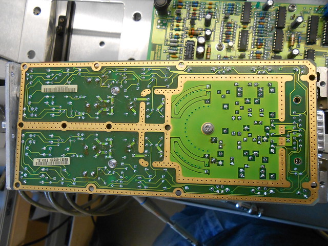
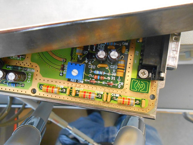
Mystery board (name turns out to be "search & lock") is at the bottom-right:


It also has a processor board, but that's probably underneath the power board here and I can't get to it without some more invasive disassembly. Meanwhile, enjoy the fact that some unfortunate PCB layout engineer got the "mirror" setting wrong in their CAD tool once:

Notice that input module which plugs into the IF board, in the overview. Nothing on the IF board looks even vaguely up to handling 1 Ghz, so all the high-frequency stuff must happen in that input module. What's in there anyways?


Lots of shielding, for one thing:

And a potentiometer-style wiper that picks off a signal partway between the two input channels?

Huh.
I couldn't get off the top cover without risking damaging something, but here's what I could get.

Some nice coax termination from the probes:

Voltage dividers, I assume, and capacitive trim for frequency response at the front-end:

So, it's measuring relative amplitude and phase, and there's an "IF board"; no matter the details, it must down-convert the input signals to some nice low intermediate frequency where it's easy to do zero-crossing detection (or AGC/limiting then mixing) to extract phase info, and precision rectification to detect amplitude, right? This much I knew at the start. But the bizarre shit inside the input module, as well as assemblies with names like "Search & Lock" (including both a 1.6 Mhz and 32 Mhz oscillator) show that the front-end is likely not as simple as just a high-frequency version of an FM receiver.
Luckily,
this service manual, while unusually short on details, mentions a 20 kHz IF, and the search & lock board sending a voltage to a VCO inside the input module which triggers a sampler.
...while
this service manual for an earlier vector voltmeter goes into far more detail, while describing the exact same types of blocks mentioned in the 8508A, showing that the principle of operation has to be very similar.
From the description in that second service manual, I learned that the down-conversion here happens not through a mixer, but through old-high-speed-oscilloscope-style "equivalent time sampling"! (otherwise known as, abusing the Nyquist frequency for fun and profit) If you don't know what that is, EDN has
a decent explanation.
Anyways, it seems the input module has a VCO which generates the sampling pulses for the sample-and-hold circuits on both input channels, and the job of the "search & lock board" is to sweep through the whole range of sampling frequencies, looking for ones that produce a 20 kHz sampled output, then choose the highest one and track it as it drifts. Once the IF board has a nice stable 20 kHz, it can apply some AGC then peak-detect and XOR to its heart's content to get amplitude and phase information. The details are the difficult part, of course, especially with a sampler that can handle a 1 Ghz input accurately.
Now the "wiper" part inside the input module makes sense though. The sampling VCO is probably that circuit with the metal-can transistor which sits behind the wiper. Let's take a look at that again:
That diode near the wiper's rotating joint, with a bit of inductor-looking PCB trace, is probably a tunnel diode as part of a pulse generator driven by the VCO. The sampling pulses are distributed to the two channels' samplers
through the wiper, whose position controls the relative sampling delay between the two channels. I'd bet this is to correct for mismatched sampling delays between the two channels due to component tolerances in each one. Where the sampling pulses enter each channel's electronics, then,...

...those two diodes at left next to the caps may either be the sampler itself, or (more likely in my opinion), additional tunnel diodes for a "local" pulse generator right next to the sampler, to clean up and sharpen the incoming timing pulses after traveling through that variable-delay trace.
Once the signals are sampled, they go to the IF board, which has some filters (that's what's in the metal cans) and variable gain (the LM13700s) for each channel before going into ICs with unreadable part numbers or HP-part-number labeling.

Won't be able to figure out exactly what's happening with the rest of it without mapping out every trace between all the generic-building-block op-amp and digital logic ICs, but we've seen the best parts of it already anyways.
Hope you've enjoyed this look inside.


