Author Topic: Cheezeball DC Load: DL24P: Pump, or Dump ???  (Read 80475 times)

0 Members and 1 Guest are viewing this topic.

Offline stts

  • Contributor
  • Posts: 27
  • Country: us
Re: Cheezeball DC Load: DL24P: Pump, or Dump ???
« Reply #200 on: September 13, 2022, 03:43:42 pm »
Good luck trying to get it to work. There is lots that you seem to be confused about. So I doubt you will get it to work. IGBT is not good for this application. Thats why nobody is using it. You need to understand the difference between the devices. If you ordered the plain dl24 board, then you ordered an inferior device. Again you didnt understand the differences. Theres lots of basic electronic info on the internet. Look everything up and figure it out before you buy other peoples stuff to "improve" it. Other people have already "improved" the plain board dl24 that you ordered. The board I posted is an "improved" version. You could have chosen that to "improve", but not with an IGBT. Good luck with your adventure.
 

Offline yuhar

  • Contributor
  • Posts: 21
  • Country: hu
Re: Cheezeball DC Load: DL24P: Pump, or Dump ???
« Reply #201 on: September 13, 2022, 07:18:23 pm »
Yes, I did order the DL24 board, without cooler... I hope will be here soon. I'm going to delve into the topic just now.
I really don't understand the "P" marking; DL24 and DL24P what is the difference; - maybe bigger fan? - sw also different (power limit in the software)?
finally found the detailed sch - really nice ( at #162 post)


DL24M  ("M" I think - because modular) not big difference; here the reverse polarity diode on heatsink this is pro (don't important part), but same smd shunt resistors, looks like there are several pieces.
I can connect paralell the FETs If I want... but not one gate resistor... no thanks.
I found sch for addon boards, but where is this  "Current Matching Adjustment"-potmeter on the main board? - for each FET?


DL24M: red fan, one FET/ board    4 pieces together for 600W
DL24M-H: 4 FETs/ board  16 pieces together for 600W
DL24MP: purple PCB in the software you can select the power till 3000W  - not recommended maybe in the future  :)  -  I think this is the last version now.
The big green resistors from the edge of the heatsink should the serial compensative resistors of each FET...

 
Yes I really don't understand why not IGBT, maybe saturation voltage? 1-2V is not too mutch. Tell me why, please.
The bipolar transistor is good load just low power (low current).

You misunderstood me, I don't want to play with kilowatts.
My first plan to "improve" the shunts and the FET exchange; will be good if the current can be 30A (on 5V (10V), maybe later more)


It would be nice to understand why the FETs dies - in my opinion, the sudden change in current, not the SOA ignoring.
« Last Edit: September 14, 2022, 08:01:57 am by yuhar »
 

Offline stts

  • Contributor
  • Posts: 27
  • Country: us
Re: Cheezeball DC Load: DL24P: Pump, or Dump ???
« Reply #202 on: September 14, 2022, 08:00:54 pm »
Here's a useful pic I found of why you don't want to use IGBTs unless that's all you got on Gilligans Island. Ill write more after I see if the picture posts. Preview don't seem to work.

Oh yea. I stumbled upon the perfect pic that should be informative for everybody that might think IGBTs could fix you up. As you can see, these 2 are different animals made for different objectives. And only one is best for draining power sources. From the chart you can see the MOSFET has a large range of Vds for ever increasing Id. That means something very big for battery draining. Its got large junction impedance that's inducing that voltage drop. And the impedance gets even larger as the device heats up. On the other hand, with the IGBTs, the range of Vce is much narrower for ever increasing Ic. So as the amps shoot for the moon, its not dumping much more watts because the junction impedance is staying pretty low. That's highly undesirable for a battery drain. And as the thermos rise, IGBT still charts with similar impedance. Absorbing way less power that what MOSFETS absorb. So when draining huge batteries with an IGBT, the power has to go somewhere. And if it's not in the IGBT heat sinks, then its the batteries that will be heating up big time. And that's very bad news. So stay away from IGBTs. Its not my "opinion", the chart says so. The MOSFET resistance IS the load that is required to drain batteries and power supplies in a way that they were designed to be drain. Converting all their energy to heating up something else. IGBTs are most efficient at transferring power to someplace else. NOT absorbing power themselves.

As for all the other "opinions" in the previous posts, the charts say MOSFETs were designed for switching purposes efficiently. The charts also say their impedance runs high in their linear operating area. But the factory charts say the impedance drops as thermos increase over the SOA. So current rises and thermos go up even more. Until you get a brief runaway and explosion. And it don't matter what current you run. Each device is made from many tiny little mosfets that are likely to fail with tiny currents run outside the SOA. My 50 amp mosfet shorted with 1.9 amps current due to thermal runaway that happened and the heat sink situation was ineffective. There is no data available that says how cool you would have to run to guarantee full life span of these unguaranteed mosfets. And since the current was split between 4 devices, my mosfet failed when sinking less than half an amp. That's very telling about the flaw that prohibits the use of "most" mosfets in the linear zone with DC current. Other design flaws can destroy these mosfets. But running mosfets outside of the SOA comes with no guarantee from the maker. And that says it all despite any other "opinions". A few mosfets were invented to guarantee DC operation in the SOA. Those are the mosfets that should be used in battery loads. Any other mosfet may work for awhile, but they will die way before their time. Several of the Chinese active load units use the same unguaranteed mosfets in their machines. Paralleling to share the load. But its a band aid. The industry method of making most mosfets make them risky to operate in the linear zone. No matter how they hook them up. So stick with the charts to avoid a lithium battery accident.

So the first paragraph is Mosfets are great compared to IGBTs. The second paragraph is the "right" mosfet is great compared to all the other mosfets. So there you go. Useful info that I didn't invent with my opinion. Hah.

And I already posted that the DL24M (black PC board) had 4 mosfets with 4 op amp circuits that self balance that don't need balancing pots and software that cranks the display up but might need a pot on the shunt to get even more than 1200watts but would absolutely need major major heat sink improvements and can run less than 4 mosfets since I'm running 3 now. So I don't need to post that again. Hah.

« Last Edit: September 14, 2022, 10:05:33 pm by stts »
 
The following users thanked this post: Sigi_cz

Offline yuhar

  • Contributor
  • Posts: 21
  • Country: hu
Re: Cheezeball DC Load: DL24P: Pump, or Dump ???
« Reply #203 on: September 15, 2022, 09:19:35 am »
Yes, as the MOSFET is ultimately resistive (the substrate has resistance), and the bipolar-transistor is a semiconductor.

Therefore, higher currents can be extracted from the IGBT after open (1-2V saturation)

- please see attached diagram (I can't do inline)

What you sent curves is actually the left edge of the output characteristic, the fully open state.
Actually, the left limit on the SOA diagrams too.
Working point adjustment is required for the adequate operating condition, that's makes the MCU.

Horizontal axis of the SOA diagram (never in the data sheets) doesn't start from zero, because the current must also be zero there - Rather we have only big numbers!  :)

What we see on yours diagram; this resistance increasing of substrate It actually works against thermal runaway... just a little - perhaps this is the reason that the VGS-, or VGE-tempco is reversed at higher voltage (finally outpot currents). (- I'm not sure if the temperature behavior affects the dynamic responses)

The linear FETs are a good choice, except his price. It is interesting to see that the Chinese are doing semiconductor multiplication, moderate success.


Yes your right; the package and the cooler thermal resistance is a very important thing, - maybe a most important in this usage.
« Last Edit: September 15, 2022, 11:45:54 am by yuhar »
 

Offline stts

  • Contributor
  • Posts: 27
  • Country: us
Re: Cheezeball DC Load: DL24P: Pump, or Dump ???
« Reply #204 on: September 15, 2022, 01:14:03 pm »
"What you sent curves is actually the left edge of the output characteristic, the fully open state."

Nope. Left end is the semi open state. The linear region that reacts in a predictable fashion with increasing control signal.

"Horizontal axis of the SOA diagram (never in the data sheets) doesn't start from zero, because the current must also be zero there - Rather we have only big numbers!"

Well if your device is designed NOT to start from zero, then you will have sparks flying every time you plug a battery in. I can do the same thing much cheaper by just putting a screw driver across the terminals. That's way cheaper than even IGBTs. And will drain the battery even quicker. :)

"Working point adjustment is required for the adequate operating condition, that's makes the MCU"

So how long do you plan to spend in reprogramming the MCU to control the non-linear region of IGBT operation? The program already in the MCU is not capable of running the non-linear side of IGBTs.

"What we see on yours diagram; this resistance increasing of substrate It actually works against thermal runaway.."

Sure, in the SOA. That's why you stay in the SOA. But If you continue to crank the Vgs, the thermos go beyond the SOA till the junctions stop being a semiconductor and start being full conductors. Then control is lost as current rises out of control. And heat rises out of control. And more nearby junctions heat up and also become full conductors. Soon the entire device starts to glow cherry red. Oh wait. There's no cherry red region plotted on the charts. Dang. All the charts must be wrong then. Lets start using IGBTs.  :-DD

"I'm not sure if the temperature behavior affects the dynamic responses"

Its clear your not sure of lots of stuff. But you think what nobody uses will be better than what they do use. So buy what you need and make what you think work. I won't be holding my breath. Or even trying to show you why data sheets are right. If you don't believe or understand what parts do, your simply going to get nowhere. So I sure don't want to waste any more on my time on nowhere.

"It is interesting to see that the Chinese are doing semiconductor multiplication, moderate success."

Moderate success... My unit blew up. I complained, got my money back, and now Aliexpress has closed my account. So I can't buy anything more from Aliexpress unless I change my name and fool them into selling stuff to me. But that's now a new crime they call identity theft that I can go to prison for. So the entire market place of Chinese goods has lost a customer because one company sells equipment with parts used incorrectly. I don't call that moderate success. More like a colossal failure.
« Last Edit: September 15, 2022, 01:34:02 pm by stts »
 

Offline yuhar

  • Contributor
  • Posts: 21
  • Country: hu
Re: Cheezeball DC Load: DL24P: Pump, or Dump ???
« Reply #205 on: September 15, 2022, 10:56:54 pm »
"Well if your device is designed NOT to start from zero..."
This is a legitimate expectation, but it is not always the case; (here is the early version or different brand of this electronic load...)

 This guy two times killd the FET, because not read the instruction; "The two current knobs should be set at the lower limit before using"


"So how long do you plan to spend in reprogramming the MCU to control the non-linear region..."
I don't think the Chinese have overthought this either; if the required current or voltage is available, the software increases the duty factor of the PWM signal until the appropriate value is reached. Regardless of how linear or not.

Even the FET driver opamp output will go down, if the current is over than a set value... (because of negative feedback from shunt). Controller is necessary to work with IGBT too, without change.

You cannot steal your identity, I think you can make a new registration, maybe it's better if you use a new email address.
There are countless other places that sell this Chinese stuff, It is sold on eBay even Amazon too.
Don't be bitter even if you have excluded yourself from aliexpress, now more and more they will be selling this everywhere.  >:D

You are not the only one who sees that the world is not moving in the right direction, but we wanted it, we do it.
« Last Edit: September 16, 2022, 12:01:15 am by yuhar »
 

Offline Squire_

  • Newbie
  • Posts: 3
  • Country: za
Re: Cheezeball DC Load: DL24P: Pump, or Dump ???
« Reply #206 on: September 18, 2022, 08:22:27 pm »
Anyone have  any idea what flavour/style it does to check or measure internal battery resistance?

I'm leaning on DC as it has be loaded to get a measurement , could one perhaps put an oscilloscope on the test leads and see if there is 1khz waveform when the "load" is on
but I'd just be guessing, anyway to actually know or to get measurement that say yes AC or no DC because of X
 

Offline stts

  • Contributor
  • Posts: 27
  • Country: us
Re: Cheezeball DC Load: DL24P: Pump, or Dump ???
« Reply #207 on: September 18, 2022, 09:25:22 pm »
Anyone have  any idea what flavour/style it does to check or measure internal battery resistance?

I'm leaning on DC as it has be loaded to get a measurement , could one perhaps put an oscilloscope on the test leads and see if there is 1khz waveform when the "load" is on
but I'd just be guessing, anyway to actually know or to get measurement that say yes AC or no DC because of X

It just uses ohms law to figure what it displays. And no point to putting a scope on it. Theres capacitors on the drive signal so the Mosfets are getting a DC signal. So mosfet current is DC.
 

Offline Squire_

  • Newbie
  • Posts: 3
  • Country: za
Re: Cheezeball DC Load: DL24P: Pump, or Dump ???
« Reply #208 on: September 18, 2022, 10:09:27 pm »
It just uses ohms law to figure what it displays. And no point to putting a scope on it. Theres capacitors on the drive signal so the Mosfets are getting a DC signal. So mosfet current is DC.

Thanks
Just wanted to make sure we're talking about the same thing here
attached image show two different resistances? does it use the same method to get the value circled in "BAT RES" milliohms
and do you think it this accurate enough?, is it not a good way to get internal resistance
« Last Edit: September 18, 2022, 10:14:49 pm by Squire_ »
 

Offline stts

  • Contributor
  • Posts: 27
  • Country: us
Re: Cheezeball DC Load: DL24P: Pump, or Dump ???
« Reply #209 on: September 18, 2022, 10:22:52 pm »

Thanks
Just wanted to make sure we're talking about the same thing here
attached image show two different resistances? does it use the same method to get the value circled in "BAT RES" milliohms
and do you think it this accurate enough?, is it not a good way to get internal resistance

Well its not that big a deal. Its hard to know how many decimal places its accurate for. But its good for comparing one battery to another. Thats really the important thing when grouping matching batteries. For other more scientific uses, aint no way Id use a unit like this. Its got problems just running without self destructing.

As far as 2 different RES readings, these unit have 4 wire device connection. the Big Res is the resistance of the entire current circuit which includes the resistance in the wire as high current runs thru it. Small voltage drop there throws off readings abit. The second pair of connection wires has no current running thru them. That gives a more accurate battery RES reading. So always use 4 wires to connect your batteries since that is the more accurate way. Older units like this had just 2 wire connections. The "engineers" were learning. Hah.
« Last Edit: September 18, 2022, 10:48:48 pm by stts »
 

Offline ledtester

  • Super Contributor
  • ***
  • Posts: 3035
  • Country: us
Re: Cheezeball DC Load: DL24P: Pump, or Dump ???
« Reply #210 on: September 18, 2022, 10:48:23 pm »
It just uses ohms law to figure what it displays. And no point to putting a scope on it. Theres capacitors on the drive signal so the Mosfets are getting a DC signal. So mosfet current is DC.

Thanks
Just wanted to make sure we're talking about the same thing here
attached image show two different resistances? does it use the same method to get the value circled in "BAT RES" milliohms
and do you think it this accurate enough?, is it not a good way to get internal resistance

The resistance on the left is just the effective resistance of the load - and that's just V/I for the measured values of V and I at that instant. It therefore can change with time.

The battery internal resistance is likely measured only at the beginning of the load test. They take the battery voltage with no load (V0) and the the voltage right after the load is applied (V1).  The internal resistance is computed by (V0-V1)/I1 where I1 is the current measured right after the load is applied.
« Last Edit: September 18, 2022, 11:17:09 pm by ledtester »
 

Online jorgemef

  • Regular Contributor
  • *
  • Posts: 134
  • Country: pt
Re: Cheezeball DC Load: DL24P: Pump, or Dump ???
« Reply #211 on: September 18, 2022, 11:01:47 pm »
Hello,

In my DL24 the microprocessor stopped working/didn't started. Looking in this thread, I got the PDF for it (HC32F030E8PA) in chinese, translated to english and followed the pins function/voltage. All good except voltage in pin 6 (resetb) which stayed under 0,7v ->this is threshold value, and should be 3.3v in normal operation. There is pullup resistor of 10k. To diagnose first i injected 1,5V with multimeter set for reading diodes and it started, so the problem was this circuit. After all the resetb capacitor which i think delays the reset release time, was failing/leaking. Replaced it with a new one (100nf as per the datasheet example), and all is working fine again. Hope this may help someone.

Cheers,
Jorge
 
The following users thanked this post: vehiculeselectriques, Brumby, Terminux

Offline stts

  • Contributor
  • Posts: 27
  • Country: us
Re: Cheezeball DC Load: DL24P: Pump, or Dump ???
« Reply #212 on: September 18, 2022, 11:23:08 pm »
Hello,

In my DL24 the microprocessor stopped working/didn't started. Looking in this thread, I got the PDF for it (HC32F030E8PA) in chinese, translated to english and followed the pins function/voltage. All good except voltage in pin 6 (resetb) which stayed under 0,7v ->this is threshold value, and should be 3.3v in normal operation. There is pullup resistor of 10k. To diagnose first i injected 1,5V with multimeter set for reading diodes and it started, so the problem was this circuit. After all the resetb capacitor which i think delays the reset release time, was failing/leaking. Replaced it with a new one (100nf as per the datasheet example), and all is working fine again. Hope this may help someone.

Cheers,
Jorge

Awesome. You are my kind of bud. Theres a schematic to this unit posted in earlier threads that can be of help when things go wrong. Its a good guide but it doesnt have the exact same parts from model to model.
 
The following users thanked this post: vk3em, Terminux

Offline yuhar

  • Contributor
  • Posts: 21
  • Country: hu
Re: Cheezeball DC Load: DL24P: Pump, or Dump ???
« Reply #213 on: September 19, 2022, 08:34:03 am »
The internal resistance measurement can be "continuous" if dV/dI is the formula.
If time has passed - meas interval is 30 seconds or a minute for example; the calculation is performed from the changes.

(- I don't have a device yet, I'm just guessing, sorry, how real it is, the one who uses it can say better)
« Last Edit: September 19, 2022, 10:43:49 am by yuhar »
 

Offline stts

  • Contributor
  • Posts: 27
  • Country: us
Re: Cheezeball DC Load: DL24P: Pump, or Dump ???
« Reply #214 on: October 02, 2022, 06:40:11 pm »
I improved my DL24M black edition. Used stuff  I had laying around. The board already has all the circuits for running 4 mosfets. No need for any of those add on boards. Just needs MUCH better heat sinking. And the proper MOSFETs for this task. I used 8 and 10 gage wiring from car stereo wiring kits I got when SUN TV and Appliance had a bankruptcy sale decades ago. Hah. I was big on car stereo till my hearing started to go bad. Then thieves stole all my car stereo stuff, and I was left with the wiring kits that I never used. They are perfect for this because the big wires are ultra flexible. And they dont put flexing stress on the MOSFET terminals. The sinks are left over CPU fans when I used heat pipes instead. They are good for 95watts each per intel. I left big loops to fuse each of the FETs since my fuse blocks were canceled when Aliexpress kicked me out.

Got it powered up now for hours at 133 watts and the thermos are only at 40C. This setup makes it easy to replace FETs and does little damage if they catch fire - after I get fuses installed. So I wont be testing on batteries yet. The power supply cant start FET fires if these flakey FETs fail. The fans are all running at a very low speed. Seems that's the speed they run if you don't use the PWM wire. I have a PWM fan controller in my junk pile somewhere. When I find it, I will hook it up to have a pot to crank up the fan speed. Then it will sink even more watts.  Ill let it burn in for a week or so just as it is, before I make more "improvements". I need to look at the fan driver. Its tiny but says it can drive these 4 fans. I may change it because cooling is too vital to leave to tiny parts.

The last pic is a surprise. I found that they put the gate via right into the source pad on one of the FETs. That's what I call a sneeky surprise. Had to paint that tiny disaster so solder wouldn't touch it. Good thing I use a big magnifier to check things out. I don't see too good any more. The top of 90% of the board is all copper for the Drain circuit. So I just scraped away a big area and soldered all the Drains in one big solder spot. The sources have to go at each source pad. But there is still enough copper there to scrape a big enough spot for 10 gage wire. Gates also go to each gate pad. But putting Drains above and Sources below keeps the big wiring from getting all bunched up.

Still running with just the 3 FETs and they are sharing the current perfectly. As expected with op amp control. No pots needed. The menu only goes up to 1200 watts, so any higher wattage setups would likely have to have a pot on the signal op amp to scale the setting current to a fraction of the output current. Easy peasy. The DL24M black edition or better is all you need. All the other models are wasted junk. Also had to scrounge up a 2 amp power supply. The 1 amp unit it came with is not enough for 4 fans. And for battery use, count on replacing all the FETs with the proper ones made for linear use. Or your just gambling with the money and work you already spent.

------------------------------------------------------------

I retrieved my other dual tracking power supply from work and put it in series with my home one. Now I'm up to 125v at 2.1amps which gives 262 watts sinking into my atorch. And the Thermos are steady at 54C on just 3 MOSFETs. And the fans are still at low speed. They can really book at high speed. You can hardly hear the 3 running right now. So this setup has some big potential. 4 MOSFETs running with fans at high speed could blow thru 600 watts. Better MOSFETs would do the same but with guaranteed relyability. And taller  Intel sinks can dump even more watts. Ill keep my eyes peeled for the taller ones that are still obsolete in todays CPU market. Maybe a box of them on Ebay or something. So 600 watts can drain a 48v 15Ah battery in an hour and 15 minutes. Thats pretty useable. Draining individual cells to test will be a breeze. Just goes to show the waste going on with the new Atorch with add on modules and bunches of the wrong kind of Mosfets. 4 devices and the right sink and fans gets you all that you could need. Only battery walls could use way more that 4 MOSFETs to get into many thousands of watts of sink power.

Here's a pic of the higher power. RES is about 60 Ohms. Thats the resistance of the power supplies. So the 2 in series split the total load of abit over 240 watts. One supply is fan cooled and pumping out heat. the other supply is heat sink cooled and runs pretty warm. Batteries dont have near this resistance. That why they run cool. Heat is bad on batteries. But worn out batteries will slowely rise in temperature as their resistance increases. Car batteries have elaborate cooling systems because they demand the maximum amps from the cells and they have to be cooled.

------------------------------------------

Very interesting. On long runs when readings get to all 999s, the unit shifts the decimal place over instead of clearing to all zeros. So there is attention to little details. In time maybe all the bugs will eventually get fixed. Hopefully the fixes get downloaded to my unit. I have not gotten a bluetooth yet to run the PC software. Cant firmware upgrade from a smart phone.
« Last Edit: October 04, 2022, 01:02:47 pm by stts »
 
The following users thanked this post: thm_w, yuhar, Sigi_cz

Offline Sigi_cz

  • Newbie
  • Posts: 6
  • Country: cz
Re: Cheezeball DC Load: DL24P: Pump, or Dump ???
« Reply #215 on: October 02, 2022, 07:35:24 pm »
Did anyone try the DL24EW ? Seems to me like combination of DL24P and DL24M-H DL24MP.
https://www.aliexpress.com/item/1005004773128494.html
« Last Edit: October 02, 2022, 07:58:09 pm by Sigi_cz »
 

Offline stts

  • Contributor
  • Posts: 27
  • Country: us
Re: Cheezeball DC Load: DL24P: Pump, or Dump ???
« Reply #216 on: October 02, 2022, 09:08:27 pm »
They are definitely making improvements when they hear there are problems. Going back to a knob for simplicity but using an encoder instead of a pot. Now the cpu can reset to zero when discharge is cut off. Its still got those 4 tiny heat sinks that mine blew up with just 100 watts. Maybe they use a different MOSFET now. They put the display back on the board. I don't like that idea. Hard to replace if it fails or gets broken. Also too close to a ton of current activity. Has a menu that goes to 3000watts. Wow. So they have big plans even if this one is not 3000 capable. You certainly don't want 3000 watts flowing under that display. Each expansion board will have another 4 mosfets and another 4 op amp control circuits. Sooo many parts that can go wrong. And only one fuse for everything. But lots of money to expand it all that much. For those teeny tiny heat sinks. The software looks like its getting much better, and they got a plug in USB interface. I saw inside my separate display. there's holes for a connector. I bet my Bafang motor interface UART will plug right in if I solder in a connector. A UART is a UART. I bet they use the same windows driver. So Ill keep what I got, but look into getting that firmware and software. This can also charge. With your own power supply hooked to it though. So this will monitor the charge activity. That's a cool thing. But mine can do it too if I can get that firmware update.

So the basic unit is $20 more for better software. But still unknown if it will not blow up with a battery. The fuse should stop it from blowing up ugly. Unless they screwed up with the fuse upgrade. They really should just fix everything at once and test it out for a year. Especially the software. I got software but its not worth jack squat.

-------------------------------------------

And here something else I dont like about the new design. That little square part at the bottom left is the CPU. On the DL24M its under the display on the separate board. When there's static in the air, people are going to be zapping that CPU when they get their fingers near that battery connector. Then there will be a bunch of posts about a new set of crazy problems that nobody will be able to fix. Clearly the designers are watching these posts and pumping out new versions to sell as we are the guinea pigs zapped with the problems.
« Last Edit: October 04, 2022, 08:51:26 am by stts »
 

Offline yuhar

  • Contributor
  • Posts: 21
  • Country: hu
Re: Cheezeball DC Load: DL24P: Pump, or Dump ???
« Reply #217 on: October 07, 2022, 07:38:24 am »
little step forward ...
It looks like this is where the development brainstorming is going  ;D
In fact, I think they reach these levels of understanding in parallel.

Really ugly PCB, ( Pink  ???)  mcu placement  - yes not looks so good. They put it away the wifi antenna too I think from gate circuit. :)

- seperate display, wifi board was better - Yes, I agree

- on 150W board this red blade fuse (10A) and this ugly 5-10A diode - why;  the FETs body diode can blow the fuse.
- the ADC input may be injured during high voltage inducted (high current terminate). I would use varistor primarily (snubber capacitor or gas filled tube) if need. - The shunt should not explode - this protects the input... I would protect the voltage input with a zener, - but this input before the fuse - not in danger.

10A - this device for the 48V battery - ok - nice, - one for little cells like 18650, - one for...
   
- large diameter cabeling, big shunt good DC FET with good cooling; then we reach the 3000W :)
_______
My small device, finally arrived in two weeks. I change the FET immediately to APT10M25BVFR (I had one before, from a bad power supply) almost same like irfp260 but large DC soa...
« Last Edit: October 07, 2022, 08:02:38 am by yuhar »
 

Offline Sigi_cz

  • Newbie
  • Posts: 6
  • Country: cz
Re: Cheezeball DC Load: DL24P: Pump, or Dump ???
« Reply #218 on: October 07, 2022, 10:50:32 am »
I wonder what the fuse voltage rating is. I doubt 100V, as it is a car fuse (usually 12/32 V).
Let's hope the next revision will keep wifi and get separated power/control board with better layout (and color  ;D).
« Last Edit: October 07, 2022, 07:32:51 pm by Sigi_cz »
 

Offline stts

  • Contributor
  • Posts: 27
  • Country: us
Re: Cheezeball DC Load: DL24P: Pump, or Dump ???
« Reply #219 on: October 07, 2022, 06:21:18 pm »
I plan on using the glass fuses the 1-1/4 style. They are cheap enough to make sense. The only thing I wonder about is what a fuse connection itself adding resistance that can make the fuse really hot at High amps. I'm not so concerned with high voltage. Mine is running 125v only because its what I have and I am keeping the current really tiny with high volts for now. Actual use will be 99% below 60 volts. The shotky diode is not even warm. It was pretty hot being right next to the original worthless heat sinks. It was being heated by the badly cooled Tranies. I looked it up and the stock schotky is rated for all 40 amps and will only get about 20 watts hot on its own. If need be I can bolt one of the 4 scrap heat sinks that's no good for FET cooling. Been running over 5 days now with my 150 watt tester that blow up when only at 100 watts and now running 262 watts with just basic cheap cooling upgrades. Been off on another project that came up that will keep me busy for a week or so, so just letting this thing sink the watts. They doubled my electric rate a few months ago, so maybe that's not a good idea. I always been paying 7cents / kwatt and now its 14 cents. All because they got rid of Trump. That Obamanation did say we all need to start paying our fair share. I guess I always been a crook. I feel so deplorable... Hah

I looked up the APT10M25BVFR and I'm not impressed with it. They drew a DC curve on it. But its heavily derated too. Only 100 volts. I'm doing more than that now. And its only 2 amps at 100v. And 5A at 50 volts. Its just not worth my time. The description says the construction is densely packed for faster switching speeds. That's the opposite of what you want for better linear relyability. So its a device that is even worse than what Atorch is using now.
« Last Edit: October 07, 2022, 06:41:25 pm by stts »
 

Offline yuhar

  • Contributor
  • Posts: 21
  • Country: hu
Re: Cheezeball DC Load: DL24P: Pump, or Dump ???
« Reply #220 on: October 07, 2022, 07:08:12 pm »
@Sigi_cz
- it looks like someone else is watching too  :-+

I wanted to write that the fuse has more than just amperage... - voltage rating (AC and DC different),  breaking capacity...

@stts
yes the fuse have resistance, and the fuse holder getting hot if not strong enough  (connecting resistance, low quality holder...) but  this should be a much smaller loss like the series schottky - You do not need tat
- remove the series schottky and pay attention to the polarity when connect the terminals - if not; it is necessary to replace the fuse :)

for your design is desigh definitely the the world of Igbts. You can use the SOT-227 package too...

You think APT10M25BVFR even worse than Irfp260N, yes only 100V only 150°C junction temp... (but same to-247 package, and a little lower Rthjc) - You can find easily better, yes.

- imagine the DC curve of Irfp260N on step lower than 10mS cuve; is the 100mS cuve and even below; that is the DC curve - You don't have much current left.
A drawn curve is still better than an undrawn one, - in my opinion


I thinking about prevent high voltage arc; maybe a varistor should be used before and after the fuse?
Maybe one between the connecting terminals (long cables fom battery - high inductance) and one in parallel with the fuse (and one capacitor too - to stop the impulse under the varistor voltage)

Does anyone have an idea about this?
« Last Edit: October 07, 2022, 09:25:55 pm by yuhar »
 

Offline stts

  • Contributor
  • Posts: 27
  • Country: us
Re: Cheezeball DC Load: DL24P: Pump, or Dump ???
« Reply #221 on: October 07, 2022, 10:16:11 pm »
@yuhar

I dont care about loss. I like the shotky diode. He's my little buddy. And the fuse getting hot enough to melt plastic and the wire insulatiuon to degrade it over time is my only concern. I can always switch up to bigger more expensive fuses, so I pay $20 or more per blow out event, but then my happiness grin will start to shrivel up.

And I would be an utter fool to switch to igbts. So that won't be happening.
And an "undrawn curve" is more honest than an embelished curve on a high density device. You have no idea what your doing and so I leave you too it.
 

Offline yuhar

  • Contributor
  • Posts: 21
  • Country: hu
Re: Cheezeball DC Load: DL24P: Pump, or Dump ???
« Reply #222 on: October 08, 2022, 05:54:18 am »
We are not walking the same path, My road is parallel than yours; sespect.

My goal is stable 30A 200W-300W in the same little pcb, with one heating semiconductor and one cpu cooler.

Yours goal; looks to me; - stable 60-100V or more, and 5-10A or more, with multiple semiconductors and coolers...


If we are leaving the earth, we are going out into space, we reach the dream world, the world of 1000Ws, then 2kW, and then 3kW power.  8)
There may be obstacles and physical limits along the way. During I leave the 20A current level; the little buddy smd-schottkys life must be saved.
Yes, your friend can do a little better on that little heatsink. If you don't go higher than 20A current, you have nothing to worry about, also not for fuse heating...

I had also little experience in car audio - long time ago I worked as an employee for a few years in a car-audio and car-electric garage;
We used somthing like this type fansy, gold-plated, expensive fuse. - which once got really hot


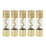
I know there is a better fuse holder for this type of fuse, but the Hungarian customers wanted high volume, power and not the expensive equipment.

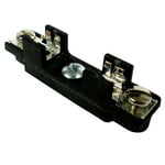
Then we started to use this type fuses (- for pennies):
     
- the M5 or M6 screws was strong enough no more contact heating. 

On the electronic load, I say goodbye to the diode-friend in the short term, and I will solder one SMD fuse 35 or 40A (125VDC / 1000A breaking capacity, and less than 2mΩ resistance) to the same place.

On the sidelines of the discussion IGBT vs MOSFET:
there was a similar topic before: https://www.eevblog.com/forum/projects/igbt-vs-mosfet-for-dummy-load/

I asked the creator of the topic (OM2220) in private message; he finally using a darlington transistor, not an IGBT
He advised me to choose the cheapest one (FET, Darlington or IGBT), with enough safe dc operating area, You do not need linear MOSFET - wrote.

Yes, If high enough the Beta of the tranzistor, the FET-driver can drive with no problem; You can use many semiconductors if you cool them down well.

- there is no speed or linearity here, there is only heat, lots of heat.
« Last Edit: October 08, 2022, 09:20:10 am by yuhar »
 

Offline stts

  • Contributor
  • Posts: 27
  • Country: us
Re: Cheezeball DC Load: DL24P: Pump, or Dump ???
« Reply #223 on: October 08, 2022, 09:10:29 am »
Dont just post all that garbage. Put a darlington in place of the mosfet. Anyone you chose. Then put a lithium battery on the terminals. Then before you press the on button, activate your cell phone video camera. That way you can record the explosion you are certain to have. Same goes for an igbt. And it don't matter which ones. Pick any IGBT that strikes your fancy. And make sure you get the video camera running right before you even connect the lithium battery. Just in case you hit the ON button before you realize you turned the load on. You don't want to be missing any of the fireworks you are sure to get. Then you will know that your path is not even on the same planet as my path.
 

Offline yuhar

  • Contributor
  • Posts: 21
  • Country: hu
Re: Cheezeball DC Load: DL24P: Pump, or Dump ???
« Reply #224 on: October 09, 2022, 09:26:47 am »
Would it be an instant short circuit? - I don't think so.
There is a big problem if there is no fuse in the circuit.  :)

Anyway, it was interesting to hear this suggestion. -Darlington.
Due to voltage or current controlled operation, it is necessary to rethink the value of the gate (base) resistor... - it can work too.
Maybe someone will try it and even use it successfully, of course; first with a laboratory power-supply.

You've had a bad experience before. You learned the rule, You know now;  - There is only one option, using a linear MOSFETs. :) Why did You using still the original FETs? (- and not with bad results.)
In addition, you only imagine the SOA. Based on your feelings, no one has documented it.
Actually, who takes more risks, who runs unnecessary laps?
« Last Edit: October 10, 2022, 07:16:50 am by yuhar »


Share me

Digg  Facebook  SlashDot  Delicious  Technorati  Twitter  Google  Yahoo
Smf