Thought I'd contribute to the new equipment forum with a teardown & review of the Digimess HY3020 bench PSU.
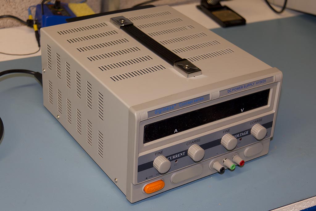
This is a pretty meaty PSU - 0-30V at up to 20A. It's a clone/re-badge of the Mastech HY3020 (but was Mastech the original or itself a clone? - there are so many of these PSUs badged by different manufacturers). The Digimess one is available from Farnell in the UK as well as Digimess themselves (and doubtless other distributors)
The design is a classic linear regulator, as can be seen in the
Mastech schematic. The output consists of 7x2N3055, 6 main pass transistors with 0.36ohm ballasts and one to provide the base drive to the other 6. To keep power dissipation manageable at high current/low output voltage settings relays are used to switch in (or out) combinations of the transformer secondaries to vary the unregulated voltage.
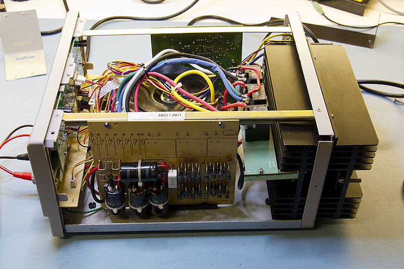
Construction is OK rather than anything else as can be seen in the following shot - the case is fairly robust and the transformer and high current wiring certainly look the part! (click on pictures for large version).
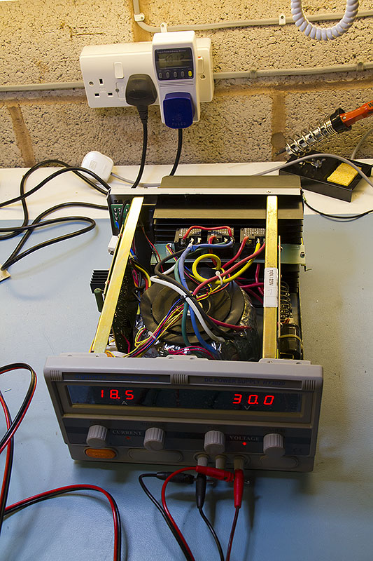
In the background you can just see the power meter reading 1012W in for 550W out so efficiency is about 54%, fairly typical for linear supplies.
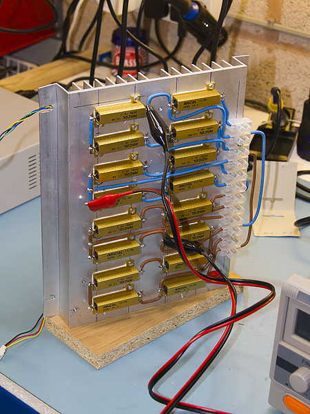
As an aside I needed to build a dummy load to test it as the full output runs to 600W - not quite as elegant as Dave's design but it gets the job done. Basically it's just 16 1 ohm 50W resistors in series with various taps to allow series/parallel combinations. At the moment it's wired as three 5ohm chains in parallel to give about 1.6ohms. With a couple of fans on the back of the heatsink it will do 600W, but it does get a bit warm!
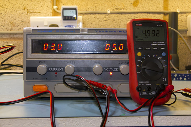
The voltmeter has been tweaked to correspond pretty closely with my UT61E, the current meter is a bit under 1% low. The eagle eyed may note that the PSU is now pulling 79W in for 15W out - now only 18% efficient

This shot shows the main bridge - 32 1N5408's and smoothing caps 4x4700uF @ 63V. Both, frankly a bit dubious. I know that the 1N5408 datasheet says they are resistant to thermal runaway but I'd rather have seen a single bridge rectifier with the appropriate rating and 63V rated caps are a bit too close to the transformers full output which is about 52V. You can see that the diodes run pretty warm as the PCB is starting to darken. The PCB is also somewhat obviously used for multiple variants.
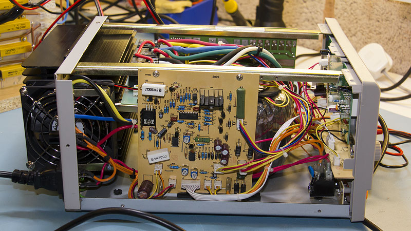
Shot from the other side showing the rest of the electronics. Both boards look fairly cheap (and it's extremely easy to lift tracks during repair). The fan placement is a bit odd as well, half in and half out of the case. The inner heatsink runs noticeably warmer than the outer as a result.
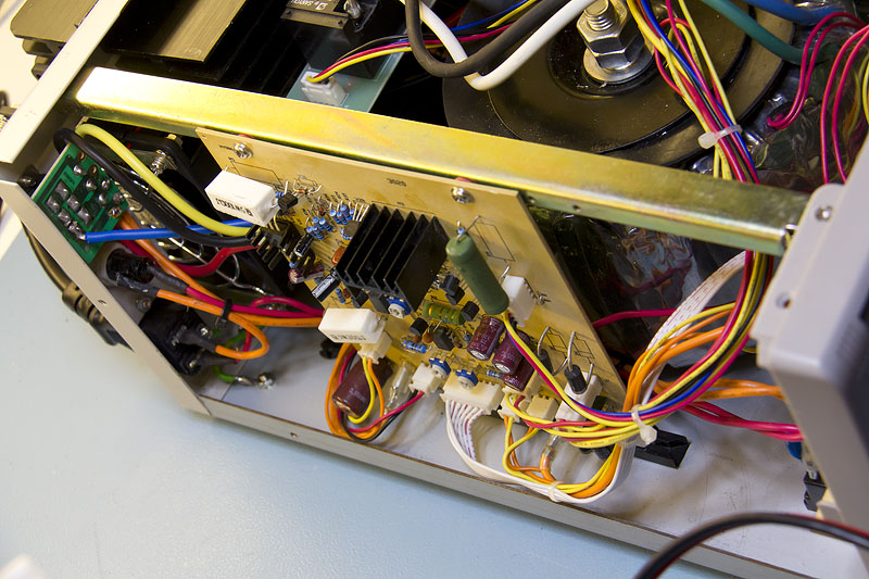
Looking down at the mains voltage selector shows that line voltage is present here so keep fingers away!
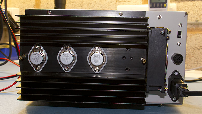
Three pass transistors are mounted on each of the heatsinks. Those with sharp vision might note that these are 2N3773's whereas I said 2N3055 above - see below.
Overall this is a competent PSU but I do have a couple of criticisms. An important missing feature is the lack of overvoltage protection. This particular one had died with 0V out - all the pass transistors were open circuit, probably because the fan had failed, however I've had a few where the failure is a shorted pass transistor and they then put out a fixed 52-56V. The fan also runs continuously, there's no temperature control and it's a bit loud.
It also suffers from the problem that all of these designs have which is the only way to set the current limit is to short the output. Also, although not too bad on this one as it has "coarse" and "fine" adjustments it can be quite hard to set the output voltage and current with any precision.
Another problem is that the thermal design is not really up to full output. The peak voltage across the pass transistors is about 26V so at 20A output each is dissipating 87W. The main heatsinks are probably managing 0.1-0.15
oC/W - certainly the outer (and cooler) one was at about 40-50
oC when pulling 20A at 15
oC ambient and sitting on 0.45
oC/W insulators the TO3 cases are going to be at 40
oC above that. Add the 2N3055 junction-to-case thermal resistance of 1.5
oC/W and the junctions are going to be at 210
oC even on a cool day.
After a bit of perusing transistor data sheets (and availability/price) I swapped the output transistors for 2N3773's. These have a better junction-to-case thermal resistance of 1.17
oC/W so the junctions should be 30
oC cooler which at least brings them under their maximum rating and allows a bit of leeway for summer. The last time I posted about these someone suggested the MJ15015 which would have been even better but I found the 3773's at just over a quid each and the MJ's were about £3, I decided the extra margin wasn't worth the cost.
I'll try to get some voltage curves and ripple measurements from it in the next day or two and add them to the review.


