Author Topic: Dynaload DLF 100-100-1500 (100V / 100A /1500W DC load) teardown & repair  (Read 7430 times)

0 Members and 1 Guest are viewing this topic.

Offline nctnicoTopic starter

  • Super Contributor
  • ***
  • Posts: 26868
  • Country: nl
    • NCT Developments
Look what the DHL courier dragged in:


A beefy DC load has been on my wish list for a long time. I got this for $100 + $390 for shipping from an Ebay seller in the Phillipines.
The DLF 100-100-1500 DC load uses 32 MOSFETs to dissipate up to 1500W. It can do constant current, constant resistance, pulses and short circuit. The description was 'working but no display'. More about that later. To be honest the DC load doesn't look as huge in real life compared to the pictures. It is a relatively deep 3U unit. The top cover is bend pretty bad. I think the seller turned it inside out to make the device look better. Also some of the buttons don't stay in the depressed position.

The guts:


The primary regulator board which has the control circuitry and 16 MOSFET drivers. Each MOSFET has it's own current regulator so the DC load is basically sharing the current between the MOSFETS.

I love a good bodge in the morning:


The secondary regulator board:


Front panel PCB. I was hoping to replace the current setting pot with a 10 turns one instead of fine/coarse but I guess that is going to take some creativity.


Big ass load disconnect relay:


Current shunt and current amplifier board:


Isolation between the - input and the chassis.  :wtf:


One of the two fans and PSU:


Mains wiring:


The assembly required a hack saw:


I think I have found the reason the displays don't show anything. I'm missing a mains transformer here. I guess the DC load has been dropped which caused the mains transformer to hit the eject button.


Besides cleaning there are a few jobs to do:
1) Source a new mains transformer

2) Test whether the DC load still works. I took some initial measurements and the MOSFETs seem to be OK.

3) Redo the mains wiring properly and switch the two fans in series if they don't need replacement. Also add temperature control to the fans.

4) Take the switches out and see if they can be fixed.

5) Check the accuracy and adjust if necessary

6) Straighten the top cover and reinforce it with some aluminium L or square tube. There is enough space in the casing to add some height to the top cover.
There are small lies, big lies and then there is what is on the screen of your oscilloscope.
 
The following users thanked this post: thm_w, lem_ix, Inverted18650

Online edpalmer42

  • Super Contributor
  • ***
  • Posts: 2268
  • Country: ca
Re: Dynaload DLF 100-100-1500 (100V / 100A /1500W DC load) teardown & repair
« Reply #1 on: December 22, 2017, 11:05:50 pm »
It looks like the missing transformer was very low power.  For test purposes, you should be able to bypass it and provide DC from one or more external supplies directly to the capacitors after the rectifiers.  That would allow you to check the rest of the unit without having to source a new, multi-winding transformer.

Ed
 

Offline nctnicoTopic starter

  • Super Contributor
  • ***
  • Posts: 26868
  • Country: nl
    • NCT Developments
Re: Dynaload DLF 100-100-1500 (100V / 100A /1500W DC load) teardown & repair
« Reply #2 on: December 23, 2017, 01:38:40 am »
It appears the transformer can be bought from Mouser:
https://nl.mouser.com/ProductDetail/Bel-Signal-Transformer/DMPC-Y-15/

I forgot to mention it in the post above but all the manuals (with calibration procedures and schematics) can be found online. I just entered the transformer part value into Google and it came up with Mouser's website.
There are small lies, big lies and then there is what is on the screen of your oscilloscope.
 

Online edpalmer42

  • Super Contributor
  • ***
  • Posts: 2268
  • Country: ca
Re: Dynaload DLF 100-100-1500 (100V / 100A /1500W DC load) teardown & repair
« Reply #3 on: December 23, 2017, 03:31:55 am »
Hey, that's cheating!  :--  Transformers must be custom or discontinued.  Everyone knows that!

Seriously, I don't think I've ever sourced a replacement transformer that easily.  They've even got them in stock!  Hopefully the rest of your rejuvenation goes as smoothly!   :-+

Ed
 

Offline nctnicoTopic starter

  • Super Contributor
  • ***
  • Posts: 26868
  • Country: nl
    • NCT Developments
Re: Dynaload DLF 100-100-1500 (100V / 100A /1500W DC load) teardown & repair
« Reply #4 on: December 23, 2017, 10:49:17 am »
I'd raise you even more: the LCD panel meters are still available from Newark/Farnell. That is amazing given the DC load is 19 years old and the design itself is probably even older.
OTOH there is also a Burr-Brown multiplier chip on the board (the golden one) which is obsolete. The multiplier is used to calculate the total power dissipated by the load and shut down in case too much power is dissipated.
There are small lies, big lies and then there is what is on the screen of your oscilloscope.
 

Offline Chris56000

  • Frequent Contributor
  • **
  • Posts: 903
  • Country: gb
Re: Dynaload DLF 100-100-1500 (100V / 100A /1500W DC load) teardown & repair
« Reply #5 on: December 23, 2017, 11:13:26 am »
Hi!

It's lovely to get documentation like that - there's everything you need to sort everything from scratch!

Even the exact replacement tranny and meter modules are available new - the only thing you might need to source are switches and a replacement pair of concentric knobs!

Let us know how it goes - I've got a copy of the paperwork & I'll follow it up with hints if you get stuck with anything!

Chris WIlliams

It's an enigma that's what it is!! This thing's not fixed because it doesn't want to be fixed!!
 

Offline alm

  • Super Contributor
  • ***
  • Posts: 2858
  • Country: 00
Re: Dynaload DLF 100-100-1500 (100V / 100A /1500W DC load) teardown & repair
« Reply #6 on: December 24, 2017, 03:00:49 pm »
That is one beefy load. Thanks for posting these pictures!

Interesting airflow arrangement. Do the fans suck air from the rear, under the heat sinks and then push it out the top? Or is it supposed to go out the front?

Is it as loud as you'd expect for something that can dissipate over 1500W?

Offline nctnicoTopic starter

  • Super Contributor
  • ***
  • Posts: 26868
  • Country: nl
    • NCT Developments
Re: Dynaload DLF 100-100-1500 (100V / 100A /1500W DC load) teardown & repair
« Reply #7 on: December 24, 2017, 03:33:54 pm »
Yesterday I tested the fans to see if they need replacing (still good to go). The air gets in at the top, front and rear and goes out at the bottom side of the rear. The noise isn't that bad but then again with a few kg of aluminium attached the fans have no way to resonate through the casing. Later today I hope to have some time to test the rest of the load with seperate DC power supplies. See what else needs replacing so I can order all necessary parts in one go.
There are small lies, big lies and then there is what is on the screen of your oscilloscope.
 

Offline timgiles

  • Regular Contributor
  • *
  • Posts: 236
  • Country: se
  • Programmer, DB architect
Re: Dynaload DLF 100-100-1500 (100V / 100A /1500W DC load) teardown & repair
« Reply #8 on: December 24, 2017, 03:37:43 pm »
Gosh what a fun project  :-+

Please update over the coming weeks/months.
 

Offline nctnicoTopic starter

  • Super Contributor
  • ***
  • Posts: 26868
  • Country: nl
    • NCT Developments
Re: Dynaload DLF 100-100-1500 (100V / 100A /1500W DC load) teardown & repair
« Reply #9 on: December 26, 2017, 10:28:53 pm »
Meanwhile I got a bit further.

I hooked up 3 power supplies to the power supply board to get the 5V, 12V, 15 and -15V rails going and another (big) one to pump some current through the DC Load. Ofcourse all power supplies are set to a very low current limit setting.


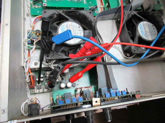
The displays worked but the +15V and -15V rails pulled a lot of current. Not good. After disconnecting the boards one by one it turned out the secondary regulator board had a short between +15V, -15V and ground. Interesting...


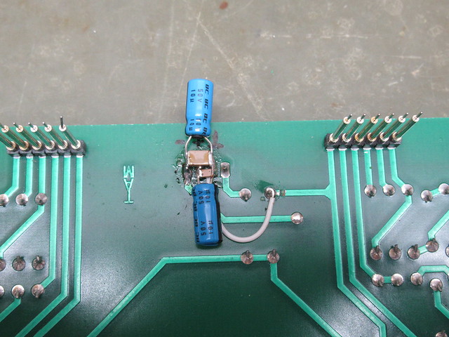
I checked all the chips but none of them where the cullprit. After pulling the secondary regulator board out it showed a bodge with two tantalum capacitors.


Both tantalum capacitors where a short (not a real surprise). I rebodged it with some electrolytics and 1nf ceramic capacitors.


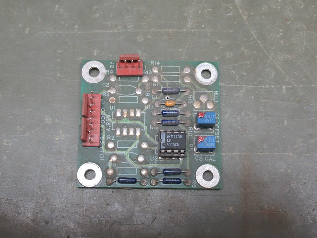
After that the DC load began to show signs of life. The voltage display showed about the right value however the current display didn't show the current through the shunt. I took the current sense board out, cleaned it and reseated the chip.
Before:

After:


Cleaning and reseating seemed to do the trick because now the current display also works.


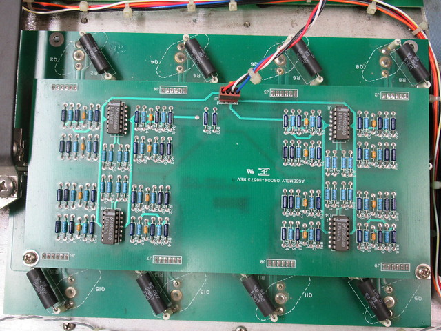
However still no go on controlling the current so I took the front panel out, cleaned it and reseated the chips.


Since I was in the neighbourhood I also took the selector switch assembly out to check what was wrong with it. It turned out the latching plate which keeps the knobs in the selected position was bend upwards which allowed the notches on the buttons to slip under it. The construction is a bit flimsy. It would have been better if they made the latching plate into an L shape so it would stay straight.


After taking the switch apart, bending the latching plate back into shape and lubricating it with a bit of vaseline (acid free grease) it works like new but it won't surprise me if the problem comes back.


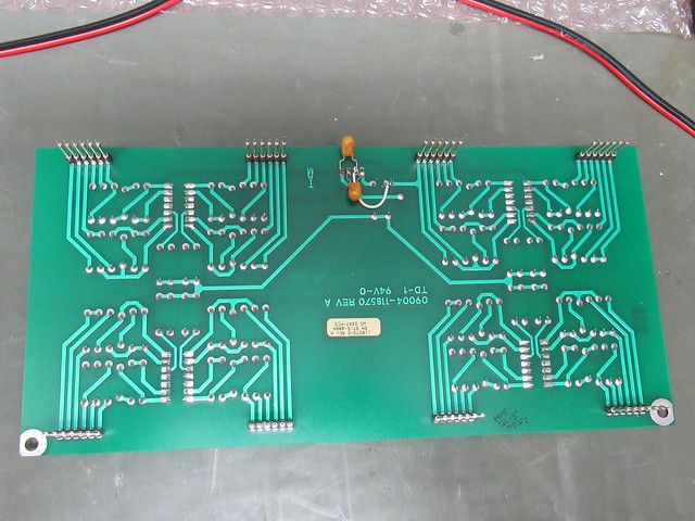
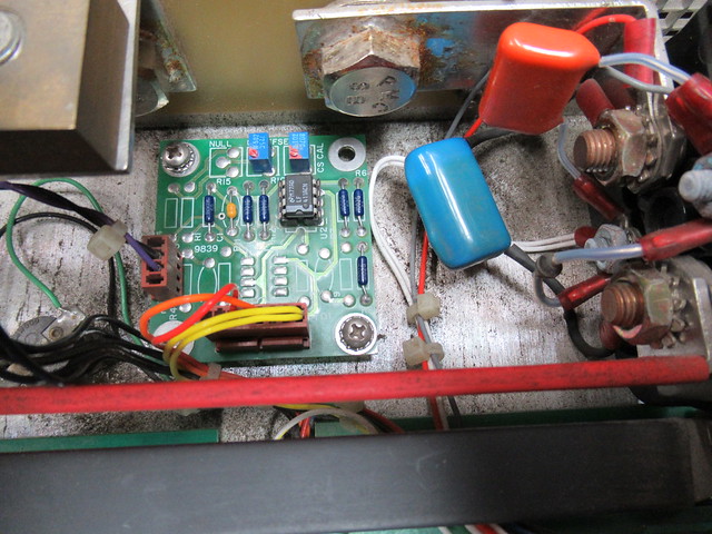
Time for a test so I put the selector switch and front panel back into the DC load. It works!!! I can set a current or constant resistance. However after a quick check I noticed I forgot to connect this little board:


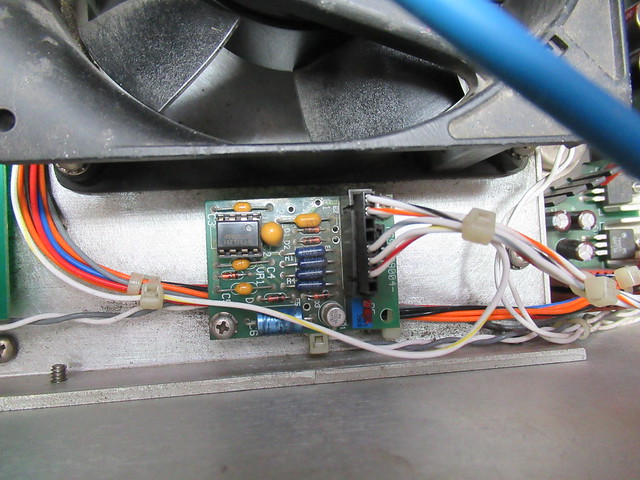
The service manual doesn't mention it so it's function is unclear. However after I connected it the DC load stopped working. I traced the wires back to where they are connected to. The wire going to the left goes to the main regulator board. All of the other wires are connected to the power supply. One of the wires goes to an PSU output with a rectified mains (100Hz pulse). This is a dead giveaway of what this board does: it is a power supply monitoring board! Since I'm powering the DC load using DC power supplies the 'mains present' signal is obviously missing and the DC load stays disabled.

Sit wrap: the DC load is working so I can go ahead with ordering replacement parts.

One of the decissions I had to make is about the power supply. I need to run the DC load from an 230V mains and I want to keep the 115V fans. I dug a little deeper into the power supply circuit.


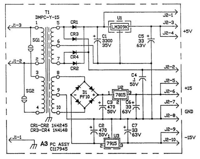
What bothers me is that the clearance on the board is marginal at best. Maybe OK for 115VAC but not for 230VAC. The designer put in solder bridges (left top part of the PCB) to select between 115VAC or 230VAC but the bridge required for 230V is covered in solder mask. And then there is also the small gap between the pads of the primary and secondary windings. I don't want 230VAC on this board! Hell no!

This left me with the following choices:
1) Design a new PSU board (which is quite a bit of work).
2) Buy one or two chassis mount transformers and solder the outputs into the existing PSU board.
3) Modify the existing PSU board to have isolation slots.
4) Put the original transformer in and add an (internal) step-down transformer to convert 230VAC to 115VAC

After thinking about it for a while I choose to go for option 4. Option 1 is too much work, option 2 looks shoddy and option 3 requires some very carefull milling and I'm still not happy with the clearance on the mains connector. Also the use of a step-down transformer allows to rewire the unit for 115VAC if needed.

With that decission made I could order a whole load of stuff from Mouser: a mains transformer, step down transformer, mains switch, 10 turn pot + knob, 6AWG (13mm^2) lugs to connect wires to the bolts at the back and parts for the fan control board. I'm not going to change the flatcables. Although they are dirty they seem to work fine and the wires are actually used in pairs for each signal. The designer probably wanted to add extra reliability.

The thing I'm still contemplating is whether or not to add fuses to the secondary side of the mains transformer. I can imagine the original transformer overheated and failed due to the short.

To be continued...
« Last Edit: December 26, 2017, 10:43:07 pm by nctnico »
There are small lies, big lies and then there is what is on the screen of your oscilloscope.
 

Offline Inverted18650

  • Frequent Contributor
  • **
  • Posts: 875
  • Country: us
    • Test Gear Addicts
Re: Dynaload DLF 100-100-1500 (100V / 100A /1500W DC load) teardown & repair
« Reply #10 on: January 02, 2018, 07:53:11 pm »
BEAUTIFUL! Following.

Offline nctnicoTopic starter

  • Super Contributor
  • ***
  • Posts: 26868
  • Country: nl
    • NCT Developments
Re: Dynaload DLF 100-100-1500 (100V / 100A /1500W DC load) teardown & repair
« Reply #11 on: January 03, 2018, 10:46:35 pm »
Time for another update. The parts have arrived so time to put things back together.

First let's fit a transformer onto the PSU board. I still can't believe they sell these transformers after 20 years:


In order to allow for 230V operation I bought a 100VA transformer with 115/230V primary and 115V secondary. I also bought a barrier terminal and made a bracket to mount the barrier terminal on top of the transformer:


Then onto mounting the 10 turn current adjust potmeter. I had to enlarge the existing hole slightly to get as much as the axis sticking out the front.


In order to mount the transformer onto the bottom plate I had to take it out which revealed the heatsinks:


One of the things I wanted to change was the exposed mains in several areas. For this purpose I also ordered a new mains switch. From experience I know soldering on mains switches is tricky because the contacts melt away quickly. I took the original wiring loom out completely and started rewiring. I got some new contacts to crimp onto the wiring of the PSU but I re-used the old connector housing (Molex KK 396)


Rewiring done! No more exposed mains and all mains wires in a braided sleeving neatly tied down away from the low voltage wiring. Another addition is a mains filter and finger guards on the fans. I also washed the ribbon cables because they looked moldy so I didn't want to take the risk.


A leftover carrying strap fitted nicely into the existing holes (after running an M5 tap through them):


100A means thick 16mm^2 / 6AWG wires and lugs.


Time for testing and adjusting! The amount of adjustment required was minimal but this isn't a high precision test instrument. It is not very visible on this picture but I made all the knobs a bit shorter. The axle on the 10 turn pot is quite short and the original knobs barely held on as well. I tried to find a knob for the current adjust pot which fitted best with the existing knobs.


This empty space is for mounting a board to make the fans temperature controlled. The wires are for power and to synchronise the TRIAC with the mains frequency.


The next and final step will be mounting and testing the fan control board.
There are small lies, big lies and then there is what is on the screen of your oscilloscope.
 

Offline nidlaX

  • Frequent Contributor
  • **
  • Posts: 663
  • Country: us
Re: Dynaload DLF 100-100-1500 (100V / 100A /1500W DC load) teardown & repair
« Reply #12 on: January 03, 2018, 10:50:08 pm »
VERY nice refurb! :-+
 

Offline Inverted18650

  • Frequent Contributor
  • **
  • Posts: 875
  • Country: us
    • Test Gear Addicts
Re: Dynaload DLF 100-100-1500 (100V / 100A /1500W DC load) teardown & repair
« Reply #13 on: January 06, 2018, 01:15:54 am »
Looks great. The edit: “fact that you took the time to put a label on the” tranny mounting bracket to id the taps was a very nice touch as well.
« Last Edit: January 06, 2018, 05:16:14 pm by Inverted18650 »
 

Offline nctnicoTopic starter

  • Super Contributor
  • ***
  • Posts: 26868
  • Country: nl
    • NCT Developments
Re: Dynaload DLF 100-100-1500 (100V / 100A /1500W DC load) teardown & repair
« Reply #14 on: January 06, 2018, 10:31:31 am »
Looks great. The photo-transfer paper on the tranny mounting bracket to id the taps was a very nice touch as well.
Uuuhhh... that is a black-on-clear label from a label printer  ;)
There are small lies, big lies and then there is what is on the screen of your oscilloscope.
 

Offline Inverted18650

  • Frequent Contributor
  • **
  • Posts: 875
  • Country: us
    • Test Gear Addicts
Re: Dynaload DLF 100-100-1500 (100V / 100A /1500W DC load) teardown & repair
« Reply #15 on: January 06, 2018, 05:14:49 pm »
Oh no! Uhhhb...You busted me...I’m not a label expert.  :palm: I fixed my compliment, hopefully it’s acceptable this time.
« Last Edit: January 06, 2018, 05:27:58 pm by Inverted18650 »
 

Offline nctnicoTopic starter

  • Super Contributor
  • ***
  • Posts: 26868
  • Country: nl
    • NCT Developments
Re: Dynaload DLF 100-100-1500 (100V / 100A /1500W DC load) teardown & repair
« Reply #16 on: January 13, 2018, 12:12:39 am »
Time for the final chapter.

I have the board fitted which controls the fans based on temperature.


The sensor is an NTC resistor on a piece of thin FR4. This is glued to the aluminium with a Cyanoacrylate glue which bonds very well to FR4 and aluminium. Some hotmelt serves as a strain relief for the wires.

The bit of masking tape with the black dot is there for use with the thermal camera. The fans turn on at 40deg C and get to full throttle at 50deg C. Pumping 1.2kW into it helped to get the temperature up!

Another job is the top cover. When center punching the holes for the step down transformer I noticed that the aluminium isn't the usual soft stuff and it has a lot of tension in it. The center punches already deformed the bottom plate a little bit. Now the top cover has been banged up pretty bad and it is warped in every wich way it can. To make it somewhat straight I decided to fit a support bar. To keep it flush I used rivets.


This should be the end of the project but during testing I found it cumbersome to mount the wires at the back. For that reason I decided to do one more mod: front binding posts!


This ofcourse needed some additional internal wiring which I wanted to keep away from the rest as much as possible.


There are small lies, big lies and then there is what is on the screen of your oscilloscope.
 

Offline alm

  • Super Contributor
  • ***
  • Posts: 2858
  • Country: 00
Re: Dynaload DLF 100-100-1500 (100V / 100A /1500W DC load) teardown & repair
« Reply #17 on: January 13, 2018, 07:55:26 am »
Nice job! I imagine those binding posts are not rated for the full 100A, though.

Offline jmkasunich

  • Newbie
  • Posts: 6
Old post, but I hope the OP can help.

nctnico wrote:  "I forgot to mention it in the post above but all the manuals (with calibration procedures and schematics) can be found online."

I just acquired a couple DLF series loads.  Been searching for manuals/schematics/etc but my google-fu is apparently weak.  Any suggestions?

I have DLF 100-50-250 (little guy) and DLF 400-600-4000 (the beast).

Thanks!

John
 

Offline nctnicoTopic starter

  • Super Contributor
  • ***
  • Posts: 26868
  • Country: nl
    • NCT Developments
You can download a zip file with the service manuals here:
http://www.ko4bb.com/getsimple/index.php?id=manuals&dir=06_Misc_Test_Equipment/Transistor_Devices

Note that not all exact models are covered but it seems they put most of the loads together from standard boards so a load with similar specs and look will probably be similar enough.
There are small lies, big lies and then there is what is on the screen of your oscilloscope.
 

Offline jmkasunich

  • Newbie
  • Posts: 6
Thanks, that is a great site.  Got the docs I needed, and dropped a few $ in the jar for Didier.
 

Offline jmkasunich

  • Newbie
  • Posts: 6
Not sure if this should be here or in the "test equipment scores" thread, but I think I scored on these units.

DLF 100-50-250     (100V, 50A, 250W) was $28
DLF 400-600-4000 (400V, 600A, 4000W) was $122

I am local to the seller so no shipping costs.

The seller is a surplus dealer in Cleveland Ohio, and they recently got a boatload of the Transistor Device dummy loads.  As of today, they still have 66 units in a variety of models and ratings.  Prices range from $54 to $470.  (They had a 50% off one-day sale on Saturday when I scored.)  Listing below.

https://hgrinc.com/?all=1&view&aisle&from&to&markdowns&newarrivals&sort=p-lth&kw=transistor&per_page=120&min_price&max_price&pn=1&slug

Their business model is to initially price things moderately high, then drop prices every month or so until either someone buys it or the price reaches the scrap metal value.  Everything is AS-IS, so it's nice to be able to visit in person and at least plug the unit in.  The displays on mine light up, and the LEDs do what would be expected in response to front panel controls.  More detailed assessment will happen later, keeping my fingers crossed.


The following users thanked this post: nctnico

Online edpalmer42

  • Super Contributor
  • ***
  • Posts: 2268
  • Country: ca
Has anyone from outside the U.S. dealt with them?  Their shipping/handling fees look quite high for smaller purchases.

Ed
 

Offline jmkasunich

  • Newbie
  • Posts: 6
They primarily sell larger equipment (hundreds to thousands of lbs/kg).  While they don't discourage people from buying the small stuff, they don't go out of their way to encourage it either.
 

Offline BVH

  • Contributor
  • Posts: 26
  • Country: us
  • Searchlights to read a newpaper by at 2 miles
Re: Dynaload DLF 100-100-1500 (100V / 100A /1500W DC load) teardown & repair
« Reply #24 on: August 15, 2022, 11:47:54 pm »
I know I'm really late to the party.  I have one of these that works great. I also have the DLF 100-600-4000 big brother that has also worked great up until I went to test it for selling.  It has 10 Module Status LED's for each of the 10, 400 Watt modules.  The LED for Module #2 is on full-time now.  The load seems to work fine although I have not tried it near it's max power.  Anyone had any experience with this load and my issue?  I can't find any troubleshooting charts nor much info at all on the unit.  I have the operation manual but there's nothing in there.


Share me

Digg  Facebook  SlashDot  Delicious  Technorati  Twitter  Google  Yahoo
Smf