Author Topic: Fun With Low Leakage/Bias Current: Femtompere, Electrometer, Keithley 617  (Read 81725 times)

0 Members and 1 Guest are viewing this topic.

Offline rastroTopic starter

  • Frequent Contributor
  • **
  • Posts: 388
  • Country: 00
Several months ago I purchased a Keithley 617 electrometer (think I'm becoming a Keithley fanboy/collector).  It seemed like a fully functional unit with the exception of readings at the lowest 2 pico-amps setting.  The service procedure gives instructions for setting zero and offset on the electrometer board at the lowest pico-amps setting with no input.  The zero could be set with good stability but the there was too much variability in the 2 pico-amp range several hundred counts.  I did some research/probing but didn't find anything conclusive.  Prior posting: https://www.eevblog.com/forum/testgear/keithley-617-current-input-adjustment/msg450438/#msg450438

I held off cleaning the electrometer PCB for fear of adding or spreading contamination - thus adding new or exacerbating existing problem(s).  I finally decided to go for it.  I cleaned the critical half of the electrometer PCB with the best isopopal I could find.  I carefully scrubbed it and flushed it with IPA followed by drying with a heat gun.  I reinstalled the board and let it run for 3 days - It was better but still not there. 

A little frustrated I let it set in the closet for a few months while pursuing other projects.  I recently revisited the zero/offset procedure and surprisingly the unit was much quieter on the 2 pico-amps range.  After ~3-days of power-on, the unit was correctly zero/offset adjusted and is very stable.  This instrument is very sensitive - just moving across the floor makes it jump a couple hundred counts for a few seconds an then settle.

The FIX = TIME.  My best guess is the unit may have absorbed moisture at its previous owners location or while shipping.  It was not shipped in a sealed bag with descendant.  So altitude changes (e.g. air shipping) may have created condensation. 

While searching the web, I found some interesting information on design and cleaning/contamination for this type of instrumentation.
 
Reference Links:

http://www.edn.com/design/analog/4368681/Design-femtoampere-circuits-with-low-leakage-part-one
http://www.edn.com/design/analog/4375459/1/Design-femtoampere-circuits-with-low-leakage---Part-2--Component-selection

Cleaning PCB That Are Sensitive To Low Leakage Currents (Great before/after cleaning demonstration):
TI(National) Makes the LMP7721 (3 Femtoampere Input Bias Current Precision Amplifier) and a development board based on this chip. 
Op Amp EVM Cleaning for Femptoamp Bias Currents:
 

Offline jitter

  • Frequent Contributor
  • **
  • Posts: 793
  • Country: nl
Re: Fun With Low Leakage/Bias Current: Femtompere, Electrometer, Keithley 617
« Reply #1 on: September 05, 2015, 09:12:56 am »
While searching for something else, I stumbled on this thread and found it worth bumping up.

Yeah, very familiar. In my job for an OEM, testing and calibrating measuring instruments that we manufacture, leakage always is an issue. We're talking about an instrument with a specified input impedance of > 1 TOhm.
Cleanliness of the boards is very important. All sensitive boards are washed in an industrial pcb washer using special detergents. This is to remove the spray on flux used in the wave soldering process. This washer also dries the boards, and surprisingly, not much time between washing and testing is needed at all.

We found the biggest contributing factors to leakage were actually what types of plastics were used in connectors in combination with the weather.
Certain types of plastic (like the green Phoenix connectors) can hold quite an amount of moisture and cause leakage in warm, muggy weather that we usually have here in  the summers. The seemingly trivial act of changing to a different type of connector solved a lot of issues we were having during these months.

So, with regard to your meter, just the weather conditions may have an effect on it that's not negligible.

Comment on the video: it looks like a crude way to clean the board, but it's tried and tested, been there done that. That curve on the monitor after cleaning looks very familiar...
Also note that there are no connectors on that board with plastic insulation, just individual pins with air around it. In these low current conditions, plastics turn out not to be that good an insulator at all since it can hold moisture (depending on the type of plastic, as written above).

Also, one of Dave's earlier vids:
sounds pretty familiar. But "my" instruments aren't that sensitive that "someone farting across the other side of the factory" :-DD has a measurable influence...
« Last Edit: September 05, 2015, 09:16:02 am by jitter »
 

Offline Smith

  • Frequent Contributor
  • **
  • Posts: 376
  • Country: 00
Re: Fun With Low Leakage/Bias Current: Femtompere, Electrometer, Keithley 617
« Reply #2 on: September 05, 2015, 05:42:06 pm »
For most aplications a good cleansing with isopropanol will do. Do let it dry for a while, most people forget/neglect this and doing do can easely generate nanoamps of creepage currents. On your electrometer clean the connectors on both the cables and the device itself too.

Once you play with a (good) electrometer you will soon find out why people use expensive (triaxial) cables, and propper grounding is a must. I have made measurements where it was necisary to keep at least 2 meters distance, not to completely mess up the measurement. Just breathing, walking by or even turning your head or waving your hand can mess it up.
Trying is the first step towards failure
 

Offline free_electron

  • Super Contributor
  • ***
  • Posts: 8517
  • Country: us
    • SiliconValleyGarage
Re: Fun With Low Leakage/Bias Current: Femtompere, Electrometer, Keithley 617
« Reply #3 on: September 05, 2015, 05:58:14 pm »
one of the things people do not realise is that, when the cleaner evaporates, it cools down ( evaporation creates a cooling effect ).
this allows moisture form the surrounding air to condense .... moisture that is pretty conductive.
Professional Electron Wrangler.
Any comments, or points of view expressed, are my own and not endorsed , induced or compensated by my employer(s).
 

Offline sarepairman2

  • Frequent Contributor
  • **
  • Posts: 480
  • Country: 00
Re: Fun With Low Leakage/Bias Current: Femtompere, Electrometer, Keithley 617
« Reply #4 on: September 05, 2015, 07:42:17 pm »
you want to use a mixture of alcohol and diethyl ether for a final rinse (preferably dried under molecular sieves).

and probobly dry it with dry air or nitrogen

what free electron says holds too, waiting for a low humidity condition or using a dry hood/etc helps, you can also heat up the PCB prior to the final clean and then give it the ether rinse
« Last Edit: September 05, 2015, 07:43:48 pm by sarepairman2 »
 

Online Alex Nikitin

  • Super Contributor
  • ***
  • Posts: 1164
  • Country: gb
  • Femtoampnut and Tapehead.
    • A.N.T. Audio
Re: Fun With Low Leakage/Bias Current: Femtompere, Electrometer, Keithley 617
« Reply #5 on: September 19, 2015, 01:51:34 pm »
I've joined this forum because of the Keithley 617. I've acquired one recently just for fun (I work with electrometers daily and with low current stuff in general for many years) and found several threads here about this device. My one came in a very good working state, with the input current meeting the specs (<4fA after a warm-up). However I've worked with the 617 before and it has one particular side which annoys me - the offset temperature drift. The input dual JFET used meet the leakage current specs but not very good in the offset voltage temperature stability. I thought about a cheap way to improve the stability and (possible) the input current level too, by replacing the dual JFET with a dual opamp - the venerable (and cheap) LMC662. The result was excellent in the DC offset stability, however I couldn't compensate the input current fully. After an investigation I've found that my 617 is an early unit, from about 1984, with a different pcb, a different input JFET and without the input protection transistors (compared to the service manual available on the web)! It also features a different input current compensation circuit, working in one polarity only (negative). For the LMC662 I had to put compensation to minimum (essentially none) and was left with about -2... -3fA cold and -7... -10fA after a warm-up. I will try to update the compensation circuit later today (making it a dual polarity as in later units) and see how stable the input current with the opamps in place of JFETs will be when properly compensated. I may also add some diode protection to the input however the opamp should survive in most overload conditions without it.

Cheers

Alex
« Last Edit: September 19, 2015, 01:57:36 pm by Alex Nikitin »
 
The following users thanked this post: BravoV, baltersice, _Wim_

Offline Smith

  • Frequent Contributor
  • **
  • Posts: 376
  • Country: 00
Re: Fun With Low Leakage/Bias Current: Femtompere, Electrometer, Keithley 617
« Reply #6 on: September 19, 2015, 04:37:24 pm »
I've just cleaned a 617 yesterday, after it failed calibration. 2pA was unusable, it had more than 450fA offset and more than 80fA noise (this should not exceed 15fA). Totally cleaned the input PCB, and replaced 2 bad caps and a bad potentiometer. It now works like new.

I've posted some pictures on TiNs FTP.
« Last Edit: September 19, 2015, 04:39:07 pm by Smith »
Trying is the first step towards failure
 

Offline rastroTopic starter

  • Frequent Contributor
  • **
  • Posts: 388
  • Country: 00
Re: Fun With Low Leakage/Bias Current: Femtompere, Electrometer, Keithley 617
« Reply #7 on: September 19, 2015, 08:15:38 pm »
Hello Smith;

Thanks - that's good stuff for future reference. Could you tell us which 2 capacitors and potentiometer?  What was was wrong with them (leak, ESR, capacitance)?  What led you to suspect these 3 parts?
 Also I have no idea how to access TINs FTP - wouldn't it be better to post a couple of pictures here?

 -rastro
 

Offline yodhe

  • Contributor
  • Posts: 13
  • Country: au
Re: Fun With Low Leakage/Bias Current: Femtompere, Electrometer, Keithley 617
« Reply #8 on: September 19, 2015, 09:28:54 pm »
FTP details are on the xdevs site, but I don't know if you can access the uploads.

https://doc.xdevs.com/article/keithley-instruments/
 

Online Alex Nikitin

  • Super Contributor
  • ***
  • Posts: 1164
  • Country: gb
  • Femtoampnut and Tapehead.
    • A.N.T. Audio
Re: Fun With Low Leakage/Bias Current: Femtompere, Electrometer, Keithley 617
« Reply #9 on: September 19, 2015, 11:10:00 pm »
Here is the input bias current of the Keithley 617 with LMC662A in place of the input JFET pair for over an hour after I've adjusted it. I'll leave the logger to work overnight to see how the bias behaves.

Cheers

Alex

« Last Edit: September 19, 2015, 11:12:23 pm by Alex Nikitin »
 

Offline TiN

  • Super Contributor
  • ***
  • Posts: 4543
  • Country: ua
    • xDevs.com
Re: Fun With Low Leakage/Bias Current: Femtompere, Electrometer, Keithley 617
« Reply #10 on: September 20, 2015, 12:36:47 am »
There is no http mirror for uploads, but I usually check FTP often.  ;)

Here are Smith's photos, thanks!


YouTube | Metrology IRC Chat room | Let's share T&M documentation? Upload! No upload limits for firmwares, photos, files.
 

Offline rastroTopic starter

  • Frequent Contributor
  • **
  • Posts: 388
  • Country: 00
Re: Fun With Low Leakage/Bias Current: Femtompere, Electrometer, Keithley 617
« Reply #11 on: September 20, 2015, 02:20:32 am »
Here is the input bias current of the Keithley 617 with LMC662A in place of the input JFET pair for over an hour after I've adjusted it. I'll leave the logger to work overnight to see how the bias behaves.

Cheers

Alex


Alex,
If I understand correctly, you've replaced the (unobtainable) Q308 low leakage dual JFET with an ultra low bias current op-amp??!!  The spec's on the LMC662 look very impressive but I did not think an op-amp would be an easy fit for the dual JFET.  I'd be interested in hearing more details on your modifications...
-rastro
 

Offline Smith

  • Frequent Contributor
  • **
  • Posts: 376
  • Country: 00
Re: Fun With Low Leakage/Bias Current: Femtompere, Electrometer, Keithley 617
« Reply #12 on: September 20, 2015, 05:38:44 am »
Could you tell us which 2 capacitors and potentiometer?  What was was wrong with them (leak, ESR, capacitance)?  What led you to suspect these 3 parts?
 
 -rastro

I've replaced R348 which is used for setting the input current. It was 5K 3/4 turn pot instead of 10K used in the manual. I replaced it with a small Bourns 10K multi turn (don't know the type) and by offsetting the pins I could still set it via the original hole in the shielding (sorry, didn't make a picture afterwards). Its much easier to set a 10 or 13 turn pot than a 3/4 turn pot. Turning the old pot did nothing.

When I was at it I checked all old electrolytics because let's face it, its build around 1984. Most where fine, but two of them had quite a high ESR (capacity was fine). It were the two identical blue Ritchey (1000uF 16V if I remember correctly) caps next to the transformer on the (smaller) input PCB. I don't know the number as there was no silk and I could not find a silkscreen layout of the input board.

Unfortunately I had no time reading the EEPROM, it was version 4.2 as I remember correctly.

I am interested about the opamp conversion too. Maybe it's something for my Keithley 602 which I still have to repair. The opamp looks quite promising. Just looked at the temperature specs, and input bias should only be 2pA 2fA at 25C, and 4pA 4fA at 50C. I don't think this electrometer will hit 50C internally (although there are no ventilation holes).
« Last Edit: September 20, 2015, 09:50:44 am by Smith »
Trying is the first step towards failure
 

Online Alex Nikitin

  • Super Contributor
  • ***
  • Posts: 1164
  • Country: gb
  • Femtoampnut and Tapehead.
    • A.N.T. Audio
Re: Fun With Low Leakage/Bias Current: Femtompere, Electrometer, Keithley 617
« Reply #13 on: September 20, 2015, 09:14:10 am »
Alex,
If I understand correctly, you've replaced the (unobtainable) Q308 low leakage dual JFET with an ultra low bias current op-amp??!!  The spec's on the LMC662 look very impressive but I did not think an op-amp would be an easy fit for the dual JFET.  I'd be interested in hearing more details on your modifications...
-rastro

Fortunately, in the 617 the input FETs are just followers, so I've used opamp as two follower buffers. Works fine. 18K resistors are needed to imitate the FET's output impedance, these should be selected to match within 0.1% .The orientation of the opamp is important - pin 5 is better to use as the input pin as it is far away from the supply pins! Below is a part from the 617's circuit and a sketch of my replacement. as well as the overnight measurement of the input current (the temperature in the lab went down by about 6-7C during the night). The input current stayed almost in spec even in these conditions. I've also added 220nF film cap between the supply pins of the opamp (visible on the photo I've posted earlier), this cap could be 47nF-220nF in value, preferably film.

Cheers

Alex


« Last Edit: September 20, 2015, 09:38:37 am by Alex Nikitin »
 

Online Alex Nikitin

  • Super Contributor
  • ***
  • Posts: 1164
  • Country: gb
  • Femtoampnut and Tapehead.
    • A.N.T. Audio
Re: Fun With Low Leakage/Bias Current: Femtompere, Electrometer, Keithley 617
« Reply #14 on: September 20, 2015, 09:19:50 am »
I am interested about the opamp conversion too. Maybe it's something for my Keithley 602 which I still have to repair. The opamp looks quite promising. Just looked at the temperature specs, and input bias should only be 2pA at 25C, and 4pA at 50C. I don't think this electrometer will hit 50C internally (although there are no ventilation holes).

Femtoamps! Real input currents of the LMC662 are in a low fA region (if you keep it clean, obviously).

Cheers

Alex
« Last Edit: September 20, 2015, 09:34:29 am by Alex Nikitin »
 

Offline Smith

  • Frequent Contributor
  • **
  • Posts: 376
  • Country: 00
Re: Fun With Low Leakage/Bias Current: Femtompere, Electrometer, Keithley 617
« Reply #15 on: September 20, 2015, 09:47:19 am »
Femtoamps! Real input currents of the LMC662 are in low fA region (if you keep it clean, obviously).

You are right, I was talking about femto amps. I might give this a try. I have some other older Keithley gear with blown inputs featuring unobtainium components.

I was wondering what other people here are using electrometers for. I use them for very low current measurement on light cells, high ohms resistor and leakage measurements (10M to >10Gohms and for measurements in circuit (high impedance voltage). I must admit I occasionally use their voltage source as a voltage supply or calibration voltage.  :-+

BTW Alex, I wondered how you determined the FET output impedance resistor as 18K. I would imagine this value to be quite a lot lower.
« Last Edit: September 20, 2015, 09:58:19 am by Smith »
Trying is the first step towards failure
 

Online Alex Nikitin

  • Super Contributor
  • ***
  • Posts: 1164
  • Country: gb
  • Femtoampnut and Tapehead.
    • A.N.T. Audio
Re: Fun With Low Leakage/Bias Current: Femtompere, Electrometer, Keithley 617
« Reply #16 on: September 20, 2015, 10:11:13 am »
BTW Alex, I wondered how you determined the FET output impedance resistor as 18K. I would imagine this value to be quite a lot lower.

These FETs have (roughly) the transconductance of about 2mA/V at 1mA (~0.5K output impedance in a follower). In the 617 circuit these FETS are run at a rather low current (~25uA). The transconductance in a JFET is (again, roughly) proportional to the drain current, so for 40 times lower current the output impedance would be about 40 times higher or ~20K. These resistors are needed as the second stage on the LT1012 is an integrator relying upon the previous stage output impedance.

Cheers

Alex
 

Offline Smith

  • Frequent Contributor
  • **
  • Posts: 376
  • Country: 00
Re: Fun With Low Leakage/Bias Current: Femtompere, Electrometer, Keithley 617
« Reply #17 on: September 20, 2015, 10:28:14 am »
Thanks for the explanation  :-+
Trying is the first step towards failure
 

Offline rastroTopic starter

  • Frequent Contributor
  • **
  • Posts: 388
  • Country: 00
Re: Fun With Low Leakage/Bias Current: Femtompere, Electrometer, Keithley 617
« Reply #18 on: September 20, 2015, 10:30:18 am »
I see the LMC662A is available in a through-hole MDIP-8 package.  This might be a better choice over the SMD version.  I don't think the board is too cramped to accommodate the larger package.  It would also be easier to solder and clean up.  Also it seems like there would be more distance or physical isolation between the pins.

-rastro
 

Online Alex Nikitin

  • Super Contributor
  • ***
  • Posts: 1164
  • Country: gb
  • Femtoampnut and Tapehead.
    • A.N.T. Audio
Re: Fun With Low Leakage/Bias Current: Femtompere, Electrometer, Keithley 617
« Reply #19 on: September 20, 2015, 10:46:10 am »
I see the LMC662A is available in a through-hole MDIP-8 package.  This might be a better choice over the SMD version.  I don't think the board is too cramped to accommodate the larger package.  It would also be easier to solder and clean up.  Also it seems like there would be more distance or physical isolation between the pins.

-rastro

Yes, a DIP-8 package will be fine too, I've just had the SOIC-8 version handy, that is all.

Cheers

Alex
 

Offline rastroTopic starter

  • Frequent Contributor
  • **
  • Posts: 388
  • Country: 00
Re: Fun With Low Leakage/Bias Current: Femtompere, Electrometer, Keithley 617
« Reply #20 on: September 20, 2015, 12:36:50 pm »
Hello Alex,

The 617 I'm interested in LMC662A-retrofitting has the newer electrometer PCB because it has the input protection (dual) transistor(s).  I have 3 areas of concern with how well this modification would cross over from the older style electrometer PCB.

1. Different input current compensation circuitry:
-- This is likely a non-issue since the newer board probably just adds additional range.

2. Different input JFET (Q308):
-- How was it determined the Q308 is different between versions? (part number marking?)
-- Is there a meaningful difference between the new and old version of Q308?
-- Will the 18K resistors still provide the correct impedance matching for the newer Q308?

3. Addition of input protection circuits:
-- This should not be an issue since input off-set is adjusted out with R348.

Regards
-rastro
 

Online Alex Nikitin

  • Super Contributor
  • ***
  • Posts: 1164
  • Country: gb
  • Femtoampnut and Tapehead.
    • A.N.T. Audio
Re: Fun With Low Leakage/Bias Current: Femtompere, Electrometer, Keithley 617
« Reply #21 on: September 20, 2015, 01:03:45 pm »
Hello Alex,

The 617 I'm interested in LMC662A-retrofitting has the newer electrometer PCB because it has the input protection (dual) transistor(s).  I have 3 areas of concern with how well this modification would cross over from the older style electrometer PCB.

1. Different input current compensation circuitry:
-- This is likely a non-issue since the newer board probably just adds additional range.

2. Different input JFET (Q308):
-- How was it determined the Q308 is different between versions? (part number marking?)
-- Is there a meaningful difference between the new and old version of Q308?
-- Will the 18K resistors still provide the correct impedance matching for the newer Q308?

3. Addition of input protection circuits:
-- This should not be an issue since input off-set is adjusted out with R348.

Regards
-rastro

Non-issues on all three items, actually. I had to update the current compensation circuit anyway, newer FETs are most likely similar in parameters , just from the photos it looks like the later ones have a smaller case, and the protection transistors should not be a problem. 

Cheers

Alex

P.S. - the last measurement graph I've done today, on a fully closed and warmed-up 617:

« Last Edit: September 20, 2015, 02:53:39 pm by Alex Nikitin »
 

Offline Vgkid

  • Super Contributor
  • ***
  • Posts: 2710
  • Country: us
Re: Fun With Low Leakage/Bias Current: Femtompere, Electrometer, Keithley 617
« Reply #22 on: September 20, 2015, 03:18:47 pm »
That is pretty stable, good job.
If you own any North Hills Electronics gear, message me. L&N Fan
 

Offline jitter

  • Frequent Contributor
  • **
  • Posts: 793
  • Country: nl
Re: Fun With Low Leakage/Bias Current: Femtompere, Electrometer, Keithley 617
« Reply #23 on: September 20, 2015, 09:03:57 pm »
Those spikes in the measurements, could they be the result of popcorn noise?
 

Online Alex Nikitin

  • Super Contributor
  • ***
  • Posts: 1164
  • Country: gb
  • Femtoampnut and Tapehead.
    • A.N.T. Audio
Re: Fun With Low Leakage/Bias Current: Femtompere, Electrometer, Keithley 617
« Reply #24 on: September 20, 2015, 09:55:29 pm »
Those spikes in the measurements, could they be the result of popcorn noise?

You may call it popcorn noise if you wish  ;) . At these current level it is almost unavoidable to have some of these. Before I've closed the top cover on the 617 even some air movement may cause a spike. And even with a closed cover a small tap on the bench could cause a spike like one of those on the graph.

Cheers

Alex
 

Offline Smith

  • Frequent Contributor
  • **
  • Posts: 376
  • Country: 00
Re: Fun With Low Leakage/Bias Current: Femtompere, Electrometer, Keithley 617
« Reply #25 on: September 21, 2015, 04:59:03 pm »
I tried to read the main EEPROM today, but unfortunately this type (Hitachi HM4827128G-25) was not supported by my programmer. 

Today I found a problem regarding calibration: The device won't calibrate the current ranges. When I save the fresh calibration  via program select => stor the calibration values disappear, and the previous calibration settings reappear. The manual states this action should copy the settings to the NVRAM  (Xicor X2443P NOVRAM) memory. Voltage calibration does work. Anyone has experience wit this kind of issue?
Trying is the first step towards failure
 

Offline rastroTopic starter

  • Frequent Contributor
  • **
  • Posts: 388
  • Country: 00
Re: Fun With Low Leakage/Bias Current: Femtompere, Electrometer, Keithley 617
« Reply #26 on: September 22, 2015, 12:08:20 am »
I tried to read the main EEPROM today, but unfortunately this type (Hitachi HM4827128G-25) was not supported by my programmer. 

Today I found a problem regarding calibration: The device won't calibrate the current ranges. When I save the fresh calibration  via program select => stor the calibration values disappear, and the previous calibration settings reappear. The manual states this action should copy the settings to the NVRAM  (Xicor X2443P NOVRAM) memory. Voltage calibration does work. Anyone has experience wit this kind of issue?

Smith,
See page 7-6 of the 617 user manual "Keep in mind that the calibration jumper must be in the correct position, as described in paragraph 7.4.4."
It's possible that the voltage calibration may already have the same value in NVRAM as the new value you are trying to save - so it just appears you have saved a new value.

-rastro
« Last Edit: September 22, 2015, 12:22:46 am by rastro »
 

Offline Smith

  • Frequent Contributor
  • **
  • Posts: 376
  • Country: 00
Re: Fun With Low Leakage/Bias Current: Femtompere, Electrometer, Keithley 617
« Reply #27 on: September 22, 2015, 06:27:48 am »
I have set the jumper in the right setting. When saving calibration with the jumper on the wrong position the display says 'out' instead of 'stor'.

I am absolutely shure the voltage calibration worked as the device was far out of calibration (>1% on some settings). After adjusting the unit the voltage reading was within 1 or 2 digits of my Keithley 2000 & 6517a.

Unfortunately my programmer also doesn't support the NVRAM to make sure it writes anything. Also, the NVRAM has 256 bit for storing calibration. The device has 27 calibrated 'ranges'. So it has no more than 9,5bits for each setting, which will probably be 8 bits. Maybe I am trying to calibrate the device outside it's 'calibration working area'.

The device came in because it was out of cal on all voltage settings, some current and some resistor settings. As we don't use the coulomb measurement anywhere, none of our electrometer have calibrated coulomb settings. Maybe we should replace the damn thing, but it's only 31 years old  :D
Trying is the first step towards failure
 

Offline Smith

  • Frequent Contributor
  • **
  • Posts: 376
  • Country: 00
Re: Fun With Low Leakage/Bias Current: Femtompere, Electrometer, Keithley 617
« Reply #28 on: September 23, 2015, 06:46:54 pm »
Complete fail! You can only calibrate 4 of the current ranges.  :palm:

Thankfully my colleague noticed. After some final adjustments the 617 now works like it should. Only thing left is the jumps every now and then. Sometimes the current jumps 30fA up and then settles down in 2pA 20pA and 2nA ranges. It took some other irradicate jumps as well, but 95% of the time there is no problem.  Calibrating the pA ranges took some time, it was difficult to find 100Gohm and 1Tohm resistors, but we did.
Trying is the first step towards failure
 

Offline rastroTopic starter

  • Frequent Contributor
  • **
  • Posts: 388
  • Country: 00
Re: Fun With Low Leakage/Bias Current: Femtompere, Electrometer, Keithley 617
« Reply #29 on: September 23, 2015, 07:25:44 pm »
Smith,

Glad to hear your cal problem is solved.  How did you instrument your 100G and 1T resistors?  Box and triax connectors for shielding?

I've only checked mine against 1G ohm.  Resistors  start getting real expensive in the higher ranges and low tempcos.  If someone was going to scrap and old electrometer it would be a good time to cannibalize a few high ohm resistors for future testing or baseline.

-rastro
 

Offline jitter

  • Frequent Contributor
  • **
  • Posts: 793
  • Country: nl
Re: Fun With Low Leakage/Bias Current: Femtompere, Electrometer, Keithley 617
« Reply #30 on: September 23, 2015, 07:40:04 pm »
Those spikes in the measurements, could they be the result of popcorn noise?

You may call it popcorn noise if you wish  ;) . At these current level it is almost unavoidable to have some of these. Before I've closed the top cover on the 617 even some air movement may cause a spike. And even with a closed cover a small tap on the bench could cause a spike like one of those on the graph.

Cheers

Alex

The reason I asked is because with the instruments I work on, spikes like that may take it outside the specs set down by our customer. This happens with about 10% of the instruments. In almost all cases popcon noise in an AD797 is to blame.

It is a similar measurement taken on a 1k load with no voltage applied. The result shows offset and noise of which the latter must lie in a band of 4 nApp. Typical noise is around 2.5 nApp but peaks obviously take it outside the limits.
Tapping on the Faraday cage in which the electrodes, dummy load and differential amplifier are placed may indeed cause spikes.

I was wondering if the spikes in the graph of the Keithley could have a similar cause.
 

Offline Smith

  • Frequent Contributor
  • **
  • Posts: 376
  • Country: 00
Re: Fun With Low Leakage/Bias Current: Femtompere, Electrometer, Keithley 617
« Reply #31 on: September 23, 2015, 08:40:38 pm »
Glad to hear your cal problem is solved.  How did you instrument your 100G and 1T resistors?  Box and triax connectors for shielding?
The are mounted in metal boxes with BNC connectors on the in and output. We use these boxes for current calibration. I have a separate shielded case (diy) for connecting loose high resistance resistors (and other components). The box itself has an impedance of >2Petaohm.

The resistors become quite expensive indeed, the ones we use are about 50 - 100 euro a piece. It comes down to absolute value, stability and voltage dependency.
« Last Edit: September 23, 2015, 08:42:25 pm by Smith »
Trying is the first step towards failure
 

Online Alex Nikitin

  • Super Contributor
  • ***
  • Posts: 1164
  • Country: gb
  • Femtoampnut and Tapehead.
    • A.N.T. Audio
At last I've managed to build a proper triaxial cable for my 617. I may yet buy a proper low-noise one from Keithley, when I'll have £200 to spare though, as the Belden 9222 I've used is not a low-noise version and unless it is fixed in one position can produce quite a lot of charge. If it is not moving, I get the same 3-4fA input current readings (after the current settles down which takes a while) as without the cable, which is good. I've also measured the voltage source performance of the 617 - very good, with less than 1LSB (50mV) error over the complete range of +/-102.3V and the tempco about 30-40ppm/C .

Cheers

Alex
 

Online Alex Nikitin

  • Super Contributor
  • ***
  • Posts: 1164
  • Country: gb
  • Femtoampnut and Tapehead.
    • A.N.T. Audio
A little update on the Keithley 617. A year ago I've considered <1LSB from the voltage source a pretty good performance. It is however, one area where the K617 can be improved - and there is a good reason to do it, as the voltage source error directly affects resistance measurements in the V/I mode. 25mV (1/2 LSB) error at 100V is only 0.025% but at 10V it is 0.25% and at 1V - 2.5% ! Unless you are prepared to tweak the pot at the back of the unit to set the voltage accurately at a particular point, this error makes this kind of measurement somewhat less precise. Fortunately, the performance of the voltage source can be upgraded by changing the DAC chip - the old and venerable AD7541AJN to an improved LT version - LTC7541AKN, plus changing LM308A in the x10 voltage amplifier stage to OP97. The result is a much improved accuracy (now the maximum deviation over the whole +/-102V range is less than 5mV and most of the time it is under 3mV) and also a considerably reduced LF noise at low output voltages.

Cheers

Alex
« Last Edit: January 16, 2017, 05:22:14 pm by Alex Nikitin »
 
The following users thanked this post: cozdas, _Wim_

Offline Kleinstein

  • Super Contributor
  • ***
  • Posts: 14165
  • Country: de
For the OP conversion I am wondering why you need the super high impedance LMC662 to replace both FETs. The feedback side is not very high impedance and could use a lower noise/drift type with no problem.

For the spike like noise, this could be cosmic or radioactive background radiation, hitting something like protecting diodes. Smaller diodes (less sensitive volume) and maybe radiation shielding could help.
 

Offline MadTux

  • Frequent Contributor
  • **
  • Posts: 785
Anyone know where to find those black or red low leakage reed relays used on the electrometer input of the Keithley 617?

Just finished fixing a couple of broken K617s from ebay (collected over the years and never really had time fixing them ;-).
I now have 4 working ones and 1 with leaky relay, maybe someone knows where to find replacement.

It was the only one that refused to zero input offset current (R348 trimmer, always displayed something around -.1500pA). Initially started by cleaning electrometer board with IPA and deionized water (which actually fixed some of the other "broken" ones), which didn't help in this case. I then replaced the "magic" input JFET (Q308) with 2N5909 (~$5 on ebay), which actually works really great (one K617 had toasted input and got fixed that way), but unfortunately didn't solve the issue here. I then had the idea of disconnecting all unused relays (K307, K309, K310) from the input stage to isolate the leakage path. With all these relays disconnected, the K617 input offset current would zero without problems. I then simply reconnected relays until I the input offset current problem started again. Found 2 suspect relays this way, which were then removed from the board and measured for leakage using my trusty Radiometer IM6 Megaohm-Meter/leakage tester.

Good relay has a resistance >1000TOhm @ 900V, while the leaky one (K309) has around 5TOhms @ 900V, which apparently causes enough leakage so that the input offset current can't be zeroed any more.

BTW, the most important thing when zeroing the  input offset current is time, especially after the board was cleaned. I found that it sometimes takes a day or so until all moisture has disappeared. A hair dryer is also helpful. The +/- .0015pA  offset current mentioned in the manual are IMO also a bit optimistic. After a good warmup I easily could adjust them to +/- .0050pA, but adjusting them to within +/- .0015pA required constant fiddling on R348.
« Last Edit: August 04, 2017, 08:57:04 pm by MadTux »
 

Offline math_indy

  • Newbie
  • Posts: 3
  • Country: us
I could not find COTO 1240-0197 anywhere (aka Keithley RL-70) however I found COTO 7301-05-1000 relays (>1TOhm) in stock at Digi-key which may do if you cannot find anything else.  I "dead bugged" the new zeroing relay into the spot where the leaky relay was.

Here is a video showing the leaky relay that was replaced:


It would be nice to have some of the original relays AND a specification sheet for the original relays.  I can't find a specification sheet for 1240-0197 anywhere?

After replacing the relay it worked much better but getting full performance required cleaning BOTH circuit boards.  I got some laboratory grade methanol from eBay and used a small airbrush gun to blast the methanol onto those boards.  For safety reasons do that outside because of the flammable methanol and associated fumes that you don't want to inhale.

Does anyone know exactly how the zero-correct works?  Is it any different from suppress?  It appears that both zero-correct and suppress are executed by software.  I think this especially true because I cannot find any analog sample-and-hold so it seems just a software correction-no?
 
The following users thanked this post: rastro

Offline rastroTopic starter

  • Frequent Contributor
  • **
  • Posts: 388
  • Country: 00
Tom,
Great video and follow-up.  Great troubleshooting techniques - I'll have to remember this work around.  Hope the subtitue relay works out.  Let us know.  Also if you are going to scrap the old relay it would be interesting to open it up to see how it's built.

-rastro
 

Offline MadTux

  • Frequent Contributor
  • **
  • Posts: 785
I'm quite busy lately, so I somehow forgot to write on how I fixed it.

Anyway, these red relays are quite easy to fix. Just pull out the old reed switch tube with some pliers and put a new reed  inside the relay coil.

The real magic lies in selecting a good reed switch. Forget the cheap crap from china, only a few GOhm of isolation resistance (because they have no sulfur hexaflouride filling). They will also start to arc at relatively low voltages (300-500V, usually). The original reed switches inside the red relays aren't that great either. (in terms of arcover and isolation resistance). For replacement, I finally found some afordable Harmlin MARR5 reed switches that are rated to an isolation voltage of 1000V and an isolation resistance of at least 1TOhm and fit inside the old relay coils.

 Real isolation resistance is more like 50-100TOhm @ 1000V, just at the limit where I can measure reliably. Also couldn't measure breakdown voltage, because my isolation tester/megaohmmeter only goes up to 1000V.
http://www.ebay.com/itm/Hamlin-MARR-5-Reed-Switch-SPST-NO-1-3-A-1000-VDC-10-W-10pcs-1-Lot/122199268347?ssPageName=STRK%3AMEBIDX%3AIT&_trksid=p2060353.m2749.l2649
http://m.littelfuse.com/~/media/electronics/datasheets/reed_switches/littelfuse_reed_switches_marr_5_datasheet.pdf.pdf

The only problem with these is that they won't reliably switch at 5V supplied by the 74HC04. So you need to overvolt the 74HC04 by applying something around 8V from the output of the first preregulator stage. (from emitter of Q309, placed some ceramic caps in there for good measure, too). I initially hacked an addon board so I can use 15V from C305 directly, but I got an noisy instrument afterwards, probably because of capacitivly coupled rectified AC noise. The it occurred to me that I might just overvolt the 74HC04 with some 8V from the 1th preregulator output, which worked.

Leaky black relays are a bit more difficult to fix, because the reed switch is epoxied inside. An option might be to drill it out. But I destroyed mine in the process, so I ended up replacing them all with Harmlin MARR5 reed switches and some reed relay coils I found on ebay. Doesn't look nice, but works just as good (maybe not as good as the red relay hack, because these coils have shielding inside) The coils are held in place by some copper wire and an eyelet soldered to the PCB, btw.
« Last Edit: October 03, 2017, 10:38:23 pm by MadTux »
 

Offline rastroTopic starter

  • Frequent Contributor
  • **
  • Posts: 388
  • Country: 00
Hello MadTux;

Interesting information.  The 3 pictures you just posted look like different PCB's.  I looks like one has 3 of of the series transistors for the HV supply replaced with transistors that have different pin-out due to the crossed legs.

-rastro
 

Offline MadTux

  • Frequent Contributor
  • **
  • Posts: 785
Yes, 2 different K617, both bought broken for little money on ebay over the course of a couple of years. The one with funny electrometer drive stage transistors was especially broken, because the previous owner (dubious dealer of all sorts of test gear on ebay  ;-) had no clue on how to fix it and replaced parts at random, apparently without success. Finally sold 2 rather broken K617 as a package for a good price, which I bought. Because I couln't find the original MMPS U60 for a good price, I replaced them by MJD350, which has different pin configuration, IIRC.
« Last Edit: October 03, 2017, 11:41:03 pm by MadTux »
 

Offline razberik

  • Frequent Contributor
  • **
  • Posts: 265
  • Country: cz
math_indy: I see some problems in your approach. It is not very clear in your video, but it seems that you are touching these very sensitive areas with your fingers. Perhaps you know what are you doing and you also say that in video.
But anyway for everybody: Never touch picoamp parts with bare fingers. Of course I break this rule sometimes. ;D But I touch only leads, since there is no change in resistivity. Sensitive are insulation areas, like hi-ohm resistor bodies. When I manipulate with these parts, I use tweezers. When risk of touching, gloves are must.

I don't think methanol cleaning is the best idea when I am not absolutely sure what exactly the problem is.
Please read this topic, there are valuable information:
https://www.eevblog.com/forum/testgear/keithley-64856487-teardown/
There is also a schematic of input of this instruments. Since it is descent of K617, the principle is the same, ZeroCheck included.

Also that 1240-0197 COTO relay is a special shielded relay ! You definitely cannot replace it with 7301-05-1000. It can perhaps work in DC area since it has good insulation, but transient response would suffer. That guard shield helps condition material between contacts and outer world to zero voltage difference, so it wouldnt suffer stabilizing time.
Explained here: https://www.embedded.com/print/4375459

Modern replacement should be 1203-0147. Unfortunately no datasheet nor information on COTO website. I emailed czech and german representative yesterday about this relay since I am also interested in it! No answer yet.
1203-0147 is used in Keithley 6514 and 6517A.

I would use MadTux approach. Pull out old reed and replace it with new one. Dont screw guard foil. Perhaps Standex-Meder 1A66 reed should work too:
http://cz.mouser.com/ProductDetail/MEDER-electronic-Standex/KSK-1A66-1015/?qs=KFo7JewZbUHhbHIVxk%2FaJw%3D%3D
It seems that reed is covered with polyetylene (third best insulator after sapphire and teflon) and wrapped in shield foil. Therefore I would wrap new reed with foil and then try to insert it into coil package.

AD) Also, It is a luck this bad relay was discovered since it is really bad. But if relay has some small leakage problem, it wouldnt be discovered in nanoAmp range and unshielded arrangement.
« Last Edit: October 06, 2017, 01:17:59 pm by razberik »
 
The following users thanked this post: Alex Nikitin, glarsson

Offline rastroTopic starter

  • Frequent Contributor
  • **
  • Posts: 388
  • Country: 00
This is a really interesting discussion on the reed relays.  It seems like faulty range-relays could be a hidden/frustrating problem on many of these electrometers as they age.

It would be great to find an comparable substitute for these reed switches.  One that could be inserted in the original solenoid.  Ideally a part that has the same AMPERE-TURNs (AT) turn-on level as the original parts.  This would eliminate the need for modification to the solenoid supply.  However it seems like reed switches with higher breakdown voltages also require higher activation current through the solenoid.  I've outline some of the considerations but these parameters still need to be evaluated.  I think determining the AT value of the original reed/solenoid would be good start.

* Reed Switch Requirements

** AMPERE-TURNs (AT):
   The product of the number of turns in an electromagnetic coil
   winding and the current in amperes passing through the
   winding. Used to quantify reed switch operate and release
   sensitivities.

** Breakdown Voltage:
   Higer voltage tolereance requires higher AT due to larger gaps
   required between reeds.  What is the design requirement of the
   current reed switches?

** Hermetically Sealed:
   Is this required for high impedence?

** Form:
   SPST n.o. (Normally Open)

** Carry Current:
   This sould be fairly low???

** Insulation Resistance:
   What leakage can we measure on known working switches?


Offline Kleinstein

  • Super Contributor
  • ***
  • Posts: 14165
  • Country: de
If needed one could improve the sensitivity a little by adding a magnetic return path on top of the relay. It does not need to go all the way to the contacts and thus would not cause much extra leakage. Since the magnetic circuit is not closed, the gap at the contacts will not be that important for the sensitivity. 

Sensitive reed relay usually com in a ferromagnetic case. The case is not only a a shield for the outside, but also to improve sensitivity by a magnetic return path.

The separate reed contacts are usually just glass - these special relays use a plastics (e.g. polystyrene) cover directly around the glass. The direct contact might be important to prevent surface leakage. Usually the glass itself is a good enough isolator, but unless very dry, there can be a surface layer of water that can cause leakage.  Putting a new glass in the old plastic tube might not be enough and could be difficult. I have not seen the details, but my guess would be using a kind of heat shrinking (e.g stretching it first) on the polystyrene.
 

Offline razberik

  • Frequent Contributor
  • **
  • Posts: 265
  • Country: cz
Does it happen to you too ? You want to buy your shielded relay, you open your favourit supplier, start browsing relay section and then ... you can't find shielded relays section !  :rant:

I have few old obsolete Meder HI12-1A79 which were replaced by 1A85.
I sacrificed one and tried to install shield foil. I wasn't able to install copper foil, it simply wasn't possible. I used aluminium foil and that wasn't easy to install though.
It was really difficult to arrange the foil not to touch reed switch. Gloves wearing is absolutely must.
See photos. I didn't have time to test it yet, but I am going to work on it.

The separate reed contacts are usually just glass - these special relays use a plastics (e.g. polystyrene) cover directly around the glass. The direct contact might be important to prevent surface leakage. Usually the glass itself is a good enough isolator, but unless very dry, there can be a surface layer of water that can cause leakage.  Putting a new glass in the old plastic tube might not be enough and could be difficult. I have not seen the details, but my guess would be using a kind of heat shrinking (e.g stretching it first) on the polystyrene.
This seems to be plausible. I firstly thought that the only reason copper foil is wrapped around plastic encapsulation is only manufacturing process. But I didn't think of you mentioned.
 

Offline rastroTopic starter

  • Frequent Contributor
  • **
  • Posts: 388
  • Country: 00
razberik/Kleinstein;

I'm not sure what you mean by "sensitivity".  Does this mean lowering the amount of current required to activate/close the reed switch?
So are you saying that adding foil around the reed switch will make it activate easier?

Is the ferromagnetic casing focusing magnetic flux toward the reed switch?  Would this be similar to a torroid focusing the flux on a coil.??
 

Offline razberik

  • Frequent Contributor
  • **
  • Posts: 265
  • Country: cz
Kleistein was perhaps talking about this (see picture).
 

Offline rastroTopic starter

  • Frequent Contributor
  • **
  • Posts: 388
  • Country: 00
Kleistein was perhaps talking about this (see picture).
I'm not sure what the picture is supposed to convey.  At this point I'll just assume that 'sensitivity' is the current (VA?) required to activate the reed switch.
-rastro
 

Online Alex Nikitin

  • Super Contributor
  • ***
  • Posts: 1164
  • Country: gb
  • Femtoampnut and Tapehead.
    • A.N.T. Audio
Reading this discussion about relays I've remembered that I have a quantity of encapsulated miniature reed relays - REMtech MRFL80005, 5V operation, internal screen for 50 Ohm line impedance connection, sub-ms operating time. Just out of curiosity I've measured the resistance between open contact pins (everything else disconnected, relay suspended in the air inside a metal box I use to measure high resistance with my Keithley 617). Using V/I resistance mode I've measured about 2.2 PetaOhm = 2200 Tohm at 100V, both polarities applied (about 45fA leakage), after ~30min settling time for each polarity. I did not even clean it, just soldered straight out of the bag. Not bad for a chance eBay purchase several years ago. I use these relay for audio with good results, but it looks like they are useful for high impedance stuff too (up to 125V as that is the contact rating) !

Cheers

Alex

P.S. - tried with the relay internal screen connected to ground - the leakage at 100V is around 10fA (measured resistance ~10 Peta Ohm, with the idle current of the setup, including the K617 around 0fA (+/-2fA fluctuations, with the voltage source at 0V).


« Last Edit: October 11, 2017, 09:43:27 pm by Alex Nikitin »
 

Offline rastroTopic starter

  • Frequent Contributor
  • **
  • Posts: 388
  • Country: 00
I think you also want to check leakage from the reed contact pins to the solenoid connections also.
 

Online Alex Nikitin

  • Super Contributor
  • ***
  • Posts: 1164
  • Country: gb
  • Femtoampnut and Tapehead.
    • A.N.T. Audio
I think you also want to check leakage from the reed contact pins to the solenoid connections also.

Obviously, it is in progress right now. These measurements take time... .

Update: With both contacts connected together , shield to ground and 100V to one of the coil connections, measured resistance is about 1000T (after an hour). Tomorrow I'll try to clean it and re-measure, as I did make four solder connections now to this small package.

Cheers

Alex

P.S. - in the morning the leakage dropped to ~20fA at 100V, about 5000T measured.
« Last Edit: October 12, 2017, 01:58:31 pm by Alex Nikitin »
 

Online Alex Nikitin

  • Super Contributor
  • ***
  • Posts: 1164
  • Country: gb
  • Femtoampnut and Tapehead.
    • A.N.T. Audio
Did some more measurements on this REMtech relay, below are the results. Time scale is 10 sec per point, vertical scale 20fA per division. The leakage measured between the coil and both contacts together, the screen is connected to the screening box ground, voltages applied are 0V, +100V, 0V, -100V, 0V and +50V. The measured resistance after ~30 min is over 1000 Tohm for either 100V or 50V.

Cheers

Alex
« Last Edit: October 12, 2017, 02:30:50 pm by Alex Nikitin »
 
The following users thanked this post: 3roomlab, rastro

Offline Kleinstein

  • Super Contributor
  • ***
  • Posts: 14165
  • Country: de
Much of the shown "leakage" current seems to be due to dielectric absorption and not true leakage: Especially the curve at 0 V is pointing toward DA, as the transients look similar for the -100V to 0 step and the 0 to 100V step. While this is not true leakage, dielectric loss can be still a problem in an instrument.

It might be interesting to also have a step like 100 V to 50 V in the sequence, as here the initial DA current and leakage would be opposite sign.
 

Online Alex Nikitin

  • Super Contributor
  • ***
  • Posts: 1164
  • Country: gb
  • Femtoampnut and Tapehead.
    • A.N.T. Audio
Much of the shown "leakage" current seems to be due to dielectric absorption and not true leakage: Especially the curve at 0 V is pointing toward DA, as the transients look similar for the -100V to 0 step and the 0 to 100V step. While this is not true leakage, dielectric loss can be still a problem in an instrument.

It might be interesting to also have a step like 100 V to 50 V in the sequence, as here the initial DA current and leakage would be opposite sign.

Yes, it is mostly DA, as my overnight data also confirm. Unfortunately, DA is always present at these current levels, especially if voltages are reasonably high. I may try to do some more measurements tomorrow. I've tried 0 to 5V step and the leakage settled to <3fA step in less than 5min. 

Cheers

Alex
« Last Edit: October 12, 2017, 03:38:53 pm by Alex Nikitin »
 

Offline math_indy

  • Newbie
  • Posts: 3
  • Country: us
I got my unit working very nicely.  Here is a part 2 video that shows what I had to do to complete the repair and calibration.  Somebody mentioned that methanol maybe not a good idea but it seemed to work well and methanol is what the Keithley service manual calls for.  I sprayed it from a air-brush gun then gently dried the board with warm air.

https://youtu.be/-68-65swAag
« Last Edit: October 17, 2017, 05:12:37 pm by math_indy »
 
The following users thanked this post: rastro

Offline Kleinstein

  • Super Contributor
  • ***
  • Posts: 14165
  • Country: de
I won't expect to much trouble from the vacuum leaking out  :-DD , even with air inside this would necessarily high leakage.
I am not even sure they have vacuum. Low pressure gas could be a problem at high voltages though. Fancy HV switches might use SF6 gas under pressure. I remember using an electron microscope that had some of the HV stuff under pressure with SF6.

The problem is more likely with the surface. This could be inside the reed contacts if they were exposed to too much voltage and did deposit some metal. It could also be on the outer surface from some kind of contamination or just the plastic cover getting old. Also some glass might take up humidity, not much but it can happen and make an effect. There is a slight chance that a simple bake out of the relays could make them isolate better again.
 

Offline rastroTopic starter

  • Frequent Contributor
  • **
  • Posts: 388
  • Country: 00
I got my unit working very nicely.  Here is a part 2 video that shows what I had to do to complete the repair and calibration.  Somebody mentioned that methanol maybe not a good idea but it seemed to work well and methanol is what the Keithley service manual calls for.  I sprayed it from a air-brush gun then gently dried the board with warm air.

Thanks for taking the time to video/document this.  What do you think is the before/after performance on the LM662A modification?  Also could you post a few pictures of the electrometer PCB to see how the new parts fit mechanically.

-rastro
 

Offline cat87

  • Regular Contributor
  • *
  • Posts: 230
  • Country: nl
Funny thing... just the other day I was scouring the net for some info on what would be some figures for leakage of these kinds of Reed relays. From independent users, not from manufacturers. Of course, I didn't find anything.

And lo and behold, today I just stumble upon this thread and voila. Some useful data. Thank you  :-+

Offline math_indy

  • Newbie
  • Posts: 3
  • Country: us
PART 3 video showing the stability of the lowest current range:

https://youtu.be/NxTJ4Y7jZsY
 

Offline razberik

  • Frequent Contributor
  • **
  • Posts: 265
  • Country: cz
I'm not sure what the picture is supposed to convey.  At this point I'll just assume that 'sensitivity' is the current (VA?) required to activate the reed switch.
-rastro
Sorry for not being explanatory. I attached picture of relay which has mu-metal shielding and it should avoid "cross-talk" of excitation current when there are more relays crowded closely together. And yes, it decreases excitation current. http://pickeringrelay.com/pdfs/reed_relaymate_web-1.pdf page 6.
But this shield doesn't help in transient characteristic.

Since I have built new version of Gyro's picoammeter with some test jigs I made similar measurement to Alex.

I have a small test chamber with feedthrough BNCs. It is basically inserted between picoammeter and test current source (1.5V battery + 1TOhm resistor). Thats the orange background in graphs.

1) I attached non-modified Meder HI12-1A79 with shorted contact to feedthrough line and turned the coil ON and OFF.
Experiment was repated with my modified relay with shielding foil connected to box enclosure potential.

2) Similar experiment like Alex did. Shorted coil and put on voltage. I tried only 30V, but results can be seen.
Non shielded and shielded.

Shielding helps a LOT. It doesn't really matter in DC region since modern relay has excellent insulation materials. But I don't believe that repaired K617 would meet it's nominal transient characteristics and settling times.
 
The following users thanked this post: 3roomlab

Offline branadic

  • Super Contributor
  • ***
  • Posts: 2390
  • Country: de
  • Sounds like noise
Re: Fun With Low Leakage/Bias Current: Femtompere, Electrometer, Keithley 617
« Reply #60 on: November 09, 2018, 07:31:05 pm »
Just curios, has someone tried Standex Electronics reed relay as a direct replacement: https://standexelectronics.com/products/hi-series-reed-relay/
They claim Insulation Resistance (IR) >10^14 Ω which looks quite good.
Two version are available HI05-1A66 and HI12-1A85 with a coil voltage of 5V or 12V.

-branadic-
Computers exist to solve problems that we wouldn't have without them. AI exists to answer questions, we wouldn't ask without it.
 
The following users thanked this post: rastro

Offline branadic

  • Super Contributor
  • ***
  • Posts: 2390
  • Country: de
  • Sounds like noise
Re: Fun With Low Leakage/Bias Current: Femtompere, Electrometer, Keithley 617
« Reply #61 on: November 09, 2018, 09:56:41 pm »
Those spikes in the measurements, could they be the result of popcorn noise?

You may call it popcorn noise if you wish  ;) . At these current level it is almost unavoidable to have some of these. Before I've closed the top cover on the 617 even some air movement may cause a spike. And even with a closed cover a small tap on the bench could cause a spike like one of those on the graph.

Cheers

Alex

Looks more like what they call "Ionizing Radiation" in:
https://www.edn.com/design/analog/4375459/5/Design-femtoampere-circuits-with-low-leakage---Part-2--Component-selection

"...
Home> Analog Design Center > How To Article   
Design femtoampere circuits with low leakage - Part 2: Component selection
Paul Grohe, Texas Instruments Precision Systems Group -June 15, 2012

6 Comments
Power line noise
Powerline noise can manifest itself through many different ways. The obvious ways are the aforementioned ground loops, electrostatic and electromagnetic coupling, but there are some other avenues where line noise can infiltrate a high-impedance circuit.

For op-amps, instrumentation amps, CMOS switches and muxes, A/D's and other active devices with high impedance inputs, the input pins most likely have ESD protection or clamping structures on their input pins (as previously discussed). These structures have a direct connection to the power line, and also have inherent device capacitance across them. This small capacitance can couple noise directly into the high impedance input signal, bypassing any of the native Power Supply Rejection Ratio (PSRR) of the device. A few millivolts of "hum" or digital "hash" on the supply line can make its way through the protection diode capacitance and embed itself in the input signal.

Figure 12. Supply Noise coupled through ESD diode capacitance

Another entry point is power supply derived bias voltages, which are usually obtained through a resistive divider. The typical Vs/2 divider has only 6dB of power supply rejection without any filtering. Adding a bypass capacitor to the tap may boost this up to 20-30dB or more at high frequencies, but at low frequencies, the capacitance may not be enough to completely eliminate power line frequencies (and their harmonics). If this bias line is used to provide a bias voltages for the sensor (before the gain stage), then the noise can "modulate" the sensor signal and be amplified along with the sensor signal.

Obviously, the rule here is to keep the supplies and bias voltages as clean as possible. Very sensitive stages should be supplied from a separate supply. In most cases, a simple R-C-L filter on the supply lines will suffice.

A word of warning: When bench testing, digitally controlled power supplies can have a combination of hum, switching noise and digital "hash" on them. Also, many DMMs have a lot of digital sampling transients on their inputs. The DMMs, when connected to an analog supply to monitor the voltage, can inject digital noise into the supply lines. If you see noise on your signal that correlates with the DMM's display update rate, then turn the DMM off and see if the noise goes away.

Ionizing Radiation
One interesting phenomenon that occurs down at the femtoamp levels is the detection of naturally occurring ionizing radiation3. The most common effect is a sudden "pop" or step change in a measurement. As the particles fly by at the speed of light, they ionize the air in their wake. If the input conductors happen to be near by, they will accumulate some of this charge.

The radiation sources are both terrestrial, and extraterrestrial, and are all around us. The largest contributor is extraterrestrial. Energetic particles are generated from the sun, solar flares, exploding supernovae and other galactic sources. Those particles have come a long way to disturb your measurement! Terrestrial sources of radiation can include common materials such as ceramic, stone and granite. Radon can accumulate in enclosed underground areas.

Alpha and beta particles can be stopped with a few millimeters of aluminum, but the more energetic gamma and "X" rays (which can create the alpha and beta particles) are stopped by much more dense materials (centimeters of lead).

This phenomenon may occur once a week, or several times in one day, maybe once a year. The strikes are random in both time and amplitude, and frequency depends on circuit layout, sensitivity, altitude and construction materials.

With an integrator, this sudden accumulation of charge will look like a sharp step, but the slope of the line generally does not change. A transimpedance amplifier will show a sharp rising edge followed by an exponential decay.

The only way to minimize these events is to minimize the amount of air between the measurement nodes and the guard, as well as keeping the surface area of the input conductors to a minimum. Do not inadvertently create your own small-scale ion chamber!..."

-branadic-
Computers exist to solve problems that we wouldn't have without them. AI exists to answer questions, we wouldn't ask without it.
 
The following users thanked this post: egonotto, rastro, bsw_m

Offline MiDi

  • Frequent Contributor
  • **
  • Posts: 600
  • Country: ua
Keithley 617 incl. Fireworks
« Reply #62 on: June 13, 2019, 10:43:26 pm »
Got this interesting unit four weeks ago - including fireworks :popcorn:

Video from previous owner:


The eagle eye will catch instantly two obvious damages:


The first are two 35 year old spacers near primary tranformer that did not withstand careful handling by parcel service and dissolved to nearly dust, second one is a puff daddy.
Any suggestions for replacement of spacers?

Selection of pictures from attachement from unit as received


Strange black pcb cancer on electrometer board...

The fireworks section is located at the Diodes of HV supply for bootstrap amp with sharp edges meeting creepage distance of <1mm @>500V  :wtf:


Problem solved with piece of kapton tape and diodes as High Rider:


Next obvious site is the incontinent cap C316 (1000µF 105°C Nichicon, already replaced in ~91)


After that the unit was first fired up and first check revealed another problem.
When disabling zero check it went fast to overload.
Check of HV supply revealed unstable voltages, maybe only bad caps?

After a timeout all caps were replaced, another two of them decided to give high resistance - one was from the HV supply.
HV supply was now stable, but error still persisted - this seems to become a serious repair.

Check of supply rails showed ~0V for -5V bootstrap rail.
After desoldering LM337L (U307) it showed a bit of melted case on pins - this poor little sucker was toasted.
Guess what - the error still persisted after replacement.

Finally only Q308 remained to be the cause - this unobtainium matched dual input JFET.
Thanks to Alex the journey to femtoamps could continue by replacing it with LMC662.


Quick check: It's alive!  :-DMM

After several local cleanigs, the electrometer board was fully cleaned twice from both sides with special pcb cleaner "Kontakt LR" followed by blowing it with pressurized air from a can and repeat this with pure IPA.
After drying it at 50°C for about 2h it went back into its case, but drift and noise were horrible - even after several hours.

The next days noise did improve, now after 5 days it finally went down to ~1.2fA noise - this looks promising.
The offset could be adjusted to 0 only after shorting a resistor for balancing - in this unit this is done by changing the resistor values between Q308-1 and R335 (2 parallel resistors, one was cut from factory) and Q308-5 and R336 (pot + 2 parallel resistors - one was cut from factory)

The input bias current could not be cancelled out fully - Alex reported this.
Documentation of modification to dual rails for this early units appreciated.

Interesting that this unit seems to have some changes to that from Alex, maybe this has first revision of electrometer board.
Some parts have datecode of '91, so there was apparantly a repair/upgrade.

Big thanks to all contributors for repair documentation on 617, especially Alex for the JFET replacement!


--- to be continued ---
« Last Edit: June 14, 2019, 12:19:30 am by MiDi »
 
The following users thanked this post: TiN, rastro, alm

Offline rastroTopic starter

  • Frequent Contributor
  • **
  • Posts: 388
  • Country: 00
Midi thanks for posting your work/findings - keep adding to the collective 617 knowledge.

That was a bizarre and entertaining video.  At first I couldn't understand why it went dark  :-DD

rastro
 

Offline MiDi

  • Frequent Contributor
  • **
  • Posts: 600
  • Country: ua
Midi thanks for posting your work/findings - keep adding to the collective 617 knowledge.

That was a bizarre and entertaining video.  At first I couldn't understand why it went dark  :-DD

rastro
I will try my best to keep adding to the knowledge, stay tuned  :popcorn:

I couldn't understand it either, after watching it several times I recognized it was a cut and not "bsssst - Strasse dunkel" (ziiip - street dark)   :-DD
Sorry, only for german speakers:


PS:
My unit has rev E printed on both boards, anyone can undercut this for Electrometer Board?

MiDi: E
r6502: F
Alex: G
Smith: G
MadTux: L, G
Dave: J
math_indy: L
baltersice (Marco Reps): L
« Last Edit: August 13, 2021, 05:22:30 pm by MiDi »
 
The following users thanked this post: guenthert

Offline MiDi

  • Frequent Contributor
  • **
  • Posts: 600
  • Country: ua
One sleepless night with the statement of Kleinstein in mind an idea came up...
There was an unused ADA4530-1 sitting on the shelf for some time - would it be possible to replace the whole input amplifier with it?
In a nutshell the input amplifier formed by Q308 and U309 is just a difference amplifier.

As Q308 was already replaced and the performance was not what could be expected (I will come back to this later), there was almost nothing to lose.
First attempt looked promising in the amps ranges, but suffered from crazy offset and random jumps in volt ranges - smells like instability.
Nice thing is the direct access to preamplifier on rear panel, so no deal to quickly hook up the oscilloscope - it's ringing like a bell, journey just ends here?

The ADA4530-1 is a remarkable device considering nearly all of its properties, for example the GBW and open loop gain are higher than that of LT1012 (U309).
The 617 manual mentions that the 10nF C319 in the FB of U309 is needed for stability - maybe just a bit of isolation at the output needed to calm it down?
I throwed a 220k trimpot in and the issues disappeared, no instability in any ranges anymore.
To get the edge value for stability the trimpot was adjusted and the value measured was ~700 Ohms.
For a bit of margin a 2k2 resistor was chosen and replaced the trimpot.

This ended in the following configuration:


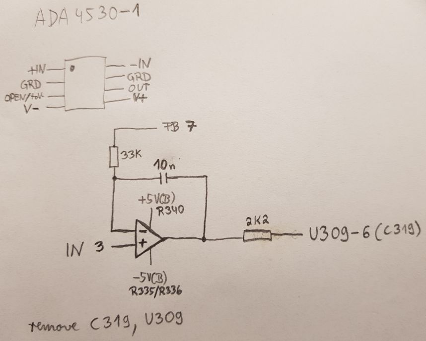
The 33k should protect the negative input up to 300V (spec: 10mA max at the inputs), for the positive input there is already more than enough protection given through 100k R333 and 10Meg R334 - even for surges (R355 not present in this unit).
As there was no 10nF in 2.5mm grid at hand, for now I put a 47nF MKS in - needs further investigation what is best value.
Seems with this replacement input protection Q311 is no longer needed as the OP AMP has input protection already - my early unit does not have it anyway.


To get an impression what this ADA4530-1 delivers, the bias current compensation and the input jack was disconnected (offset compensation already leaved with the mod in this unit).
As I would not trust old 4.5 digit ADC in this unit, my 3458A was hooked up at the preamp output.
After settling, the offset was ~300µV and bias current ~48fA (calculated) - no good sign.

I continued with performance verification of voltage ranges with help of internal voltage source.
Everything in spec according to 3458A, but the voltage source seems to have like a weared out 0V, sitting at ~200mV with horrible DNL between +-50mV.
It took me a while to realize that the output of the voltage source - even if disabled - is set to 0V and enabled all the time.
As the AD7541A DAC is in feedback, I would suggest this is the source, so put a better replacement LTC7541A on the next oversea order.

The last days the big reed relays were disconnected one after each other and bias current and offset were measured, so finally only 2pA range (K312) remained.
Disconnecting K307 improved much on bias current and now it is according to expectation ~3fA.
Every disconnected relay improved on the bias current, seems all have to be replaced - this turns into a costly repair.
Offset did not significantly change - as expected.
I guess the offset is mainly due to other sources and not from ADA4530-1 - will try to measure it in circuit later.
There is some work to do and diving into details will remain to later post...

In the meantime the search for appropriate cables was done.
For now the plan is to replace the input jack with a 3 lug triax as the options for 2 lug cables/connectors/lugs are very small and an adapter from 2 to 3 lug seems not to be economic.
Has anyone done a replacement with Keithley 7078-TRX-TBC?
For the cable I came across the Keysight N1415A, this seems to have a much better price point in comparison to the Keithley cables, any experience with this?
« Last Edit: June 22, 2019, 01:04:15 am by MiDi »
 
The following users thanked this post: egonotto, r6502

Offline TiN

  • Super Contributor
  • ***
  • Posts: 4543
  • Country: ua
    • xDevs.com
That's a rabbit hole, but you doing great. Enjoying the ride alone, thanks for all efforts.  :)
YouTube | Metrology IRC Chat room | Let's share T&M documentation? Upload! No upload limits for firmwares, photos, files.
 
The following users thanked this post: r6502

Offline rastroTopic starter

  • Frequent Contributor
  • **
  • Posts: 388
  • Country: 00
...
For now the plan is to replace the input jack with a 3 lug triax as the options for 2 lug cables/connectors/lugs are very small and an adapter from 2 to 3 lug seems not to be economic.
Has anyone done a replacement with Keithley 7078-TRX-TBC?
...

zucca did this to a K220 which is the same generation of Keithley equipment.
https://www.eevblog.com/forum/testgear/keithley-220-output-triax-connector-mod/msg393616/#msg393616

I would probably try to save any heat-shrink/insulation from the cable between the bulkhead and PCB.  I'm not sure if it is special low leakage or not.  I'd try to stick it back on maybe using heat shrink to keep it in place if you had to split it along the center.

And yes, you need to add a K220 to your shopping list!   8)

rastro
 
The following users thanked this post: MiDi


Offline MiDi

  • Frequent Contributor
  • **
  • Posts: 600
  • Country: ua
Some updates on the unit:

EDIT: Relay replacement investigation & overview moved

To give unit offset correction back, a modern approach with DAC was tested (MCP4725 - 12bit EEPROM).
For units with offset correction as stated in Datasheet (> Rev E?), this mod would be different (Rev E has different circuit for that).


Messed up the polarity, so finally the DAC is connected to GND(B) (R341) and -5V(B) (R335/R336) and set to DAC-Code 2207.
As there was no 3R3 at hand, 2R2 and 22k was chosen.


Before any questions arise:
This is another ADA4530-1 salvaged from a DIY HIZ Buffer (not needed anymore - when 617 is ready).
The DAC-Mod was done twice, first time with previous 4530 and goofed up sanity check on open unit w/o top guard cover.
Forgot to install the screw with guard connection (near empty dip-8 socket) and it showed a lot of 50Hz hum, finally I thought the op died and replaced it - with same result, but then recognized where the error came from - damn, this circuit is so sensitive :-DD

Final test today revealed no problems and with removed reed relays K307-K312, disconnected bias current adjustment & TRIAX-Input the results are impressive:


Offset (w/o zero correct): -30E-18A / 3µV (Noise: 6E-18App / 0.6µVpp -> +-3 hidden digits from GPIB)
Bias Current (15-18h): 425E-18A (STD-DEV/AC-RMS: 284E-18A)

Output pre-amp on scope (bias current measurement):


Obligatory  :box:


« Last Edit: August 21, 2019, 10:31:10 am by MiDi »
 
The following users thanked this post: TiN, bsw_m, Kosmic

Offline rastroTopic starter

  • Frequent Contributor
  • **
  • Posts: 388
  • Country: 00
I wonder if it would be possible to refurbish the old relays to bring back their original high impedance? 

Is most of the leakage failure between the reed's or also significant leakage between the reed and coil/housing?

Would methanol cleaning and then putting them in a rough vacuum a few days and maybe back flushing with nitrogen?  The setup would not be trivial but probably reasonably put together.  This would be an attempt to remove moisture and maybe some oil contamination.

Could it just be chemical reaction on the reeds and not possible to flush out?

Just some thoughts I thought I'd share.
 

Offline MiDi

  • Frequent Contributor
  • **
  • Posts: 600
  • Country: ua
When my cables arrive and input jack is exchanged, I will measure all the relays and we will see.
If leakage is from inside glas there is no chance to do anything.
On the old potted brown/black there is not much you could do besides soaking/cleaning and dry at elevated temperatures...
 

Offline MadTux

  • Frequent Contributor
  • **
  • Posts: 785
I wonder if it would be possible to refurbish the old relays to bring back their original high impedance? 

I once tried to drill out the leaky reed switch on one of these black relays, but failed horrible as the drill drifted away and mangled the poor relay coil. This were the days before I had good machining capabilities in my shed.

I would guess that on a good milling machine with rigid carbide tooling, it should be quite possible to remove the reed switch without destroying the relay coils. And then replace the reed with something good like MARR-5.

Cheap chinese reed won't do it, no SF6 filling and thereby horrible leakage and breakdown characteristics.
 

Offline MiDi

  • Frequent Contributor
  • **
  • Posts: 600
  • Country: ua
Yesterday the Triax accessories arrived (and nearly quadrupled value of unit):


I do not want to bother you with Triax exchange pron, but pics are attached  8).


The Keithley 7078-TRX-TBC is direct replacement without any problems, only the heatshrink from original shell did not survive soldering and had to be replaced - maybe it will get teflon heatshrink later.


The Keysight N1415A fits perfectly, but needs quite some force to push in / pull out.

Finally the relays were measured quickly with crude setup and not warmed up unit (all values in T\$\Omega\$):

relay # |betw. contacts |C-ES long |C-ES short |
K30730515
K308>10040300
K309702070
K310<31010
K311>100100>100
K312>500>100>100
« Last Edit: July 04, 2019, 09:01:56 pm by MiDi »
 

Offline chickenHeadKnob

  • Super Contributor
  • ***
  • Posts: 1055
  • Country: ca
To MiDi:

yes please bother us with triax pron, unlike a beautiful woman a triax connector is something I may actually hold in my hands in the near future!

I noticed you used black heat-shrink. Oh-OH, some of that stuff is no good for high impedance, carbon black or some other additive makes more conductive than is desirable for this type of application. You should measure a clean piece, maybe you got lucky. 
 

Offline MiDi

  • Frequent Contributor
  • **
  • Posts: 600
  • Country: ua
unlike a beautiful woman a triax connector is something I may actually hold in my hands in the near future!

This depends how much it is worth to you  8)

I noticed you used black heat-shrink. Oh-OH, some of that stuff is no good for high impedance, carbon black or some other additive makes more conductive than is desirable for this type of application. You should measure a clean piece, maybe you got lucky.

This is a point where I am pretty unsure if it matters there.
Have to confess that my experience in fA/P \$\Omega\$ region is non existent  :-//

My thoughts:
There are three possible leakage paths for heat-shrink on input connector:
-contact with input conductor: (teflon) insulated & creepage >1cm to both ends to bare conductor
-contact with earthed backplate: clearance of some mm
-contact with guarded enclosure: clearance of <1 mm or contact (e.g. due to wiggling / bending enclosure)

Last seems critical in normal mode, in guarded mode both should have same potential.
The other seem not to be that critical, if cleaned properly.

Edit:
All seem not to be that critical, if leakage paths are cleaned and held properly clean .
For last one I thought the inner enclosure is always at input voltage level, but it is always at guard Level - corrected that.

The construction seems a bit odd to me, why did they not use coaxial e.g. RG178 where shield takes the place of the sleeve?
« Last Edit: July 31, 2019, 11:04:15 am by MiDi »
 

Offline rastroTopic starter

  • Frequent Contributor
  • **
  • Posts: 388
  • Country: 00
To MiDi:
...
I noticed you used black heat-shrink. Oh-OH, some of that stuff is no good for high impedance, carbon black or some other additive makes more conductive than is desirable for this type of application. You should measure a clean piece, maybe you got lucky.

Perhaps you could first wrap the cable with plumbers tape which is Teflon/PTFE (probably clean it first to remove possible contaminates).  This would act as an insulation barrier to a heat shrink sleeve.

rasto
 

Offline chickenHeadKnob

  • Super Contributor
  • ***
  • Posts: 1055
  • Country: ca
It would be simpler just to use clear heat-shrink which is cheap and available and should be  polyolefin without additives. I am always suspicious of any plastic from china as they could throw in all kinds of unhelpful additives. Some pvc is just loaded with lead, apparently it helps with the flow in molding.
 
The following users thanked this post: rastro

Offline 3roomlab

  • Frequent Contributor
  • **
  • Posts: 825
  • Country: 00

relay # |betw. contacts |C-ES long |C-ES short |


Hi MiDi, what does CES long and short mean?
 

Offline MiDi

  • Frequent Contributor
  • **
  • Posts: 600
  • Country: ua
C-ES: contact to electrostatic shield
long/short: distance of the pins, there is only one ES pin between coil pin and contact pin.

coto 1240-06-2104 datasheet
 
The following users thanked this post: 3roomlab

Offline rastroTopic starter

  • Frequent Contributor
  • **
  • Posts: 388
  • Country: 00
It would be simpler just to use clear heat-shrink which is cheap and available and should be  polyolefin without additives. I am always suspicious of any plastic from china as they could throw in all kinds of unhelpful additives. Some pvc is just loaded with lead, apparently it helps with the flow in molding.
Sounds good...
 

Offline JxR

  • Supporter
  • ****
  • Posts: 352
  • Country: us
Fortunately, the performance of the voltage source can be upgraded by changing the DAC chip - the old and venerable AD7541AJN to an improved LT version - LTC7541AKN, plus changing LM308A in the x10 voltage amplifier stage to OP97.

I purchased a 617 a couple weeks ago, and so far this is the only modification I have done to it.  It was definitely an improvement on the voltage output accuracy.  It varies a bit, but it is always 8mV or less from whatever is set now.

I also discovered that apparently I purchased a 617-HIQ, although it wasn't advertised as such. It has a big ass 1uF film capacitor in the analog section that I haven't seen in anyone else's pics. It is an L-revision board, and has a B5 revision firmware (I copied and uploaded the firmware to xdevs, although probably not useful to anyone).

All of my accessories are just about here (including the 100G 1% resistor), so I hope to go through the calibration procedures with it this weekend (although it isn't too far off from my initial tests). I guess I will be skipping the Columbs cal, since I don't have the procedure for the HIQ version.  Overall, it is pretty clean on the inside and seems fairly stable in the 2pA range already.
« Last Edit: July 15, 2019, 07:08:47 pm by JxR »
 
The following users thanked this post: MiDi

Offline rastroTopic starter

  • Frequent Contributor
  • **
  • Posts: 388
  • Country: 00
I haven't seen any documentation on the 617-HIQ although I have seen a few references to it on some documents on the internet. 
 

Offline JxR

  • Supporter
  • ****
  • Posts: 352
  • Country: us
I haven't seen any documentation on the 617-HIQ although I have seen a few references to it on some documents on the internet.
Same. I have a copy of the Rev G manual everyone else does I expect, which stops at revision K on the analog board. I'm keeping an eye on eBay just in-case I see a manual pop up that is later than revision G. I don't expect to find anything, but I will certainly scan and upload it if I do.

I even bought a 1000pF +/- 0.25pF capacitor to do the coulumb cal (although I honestly would probably never use that feature).  Just figured I would do it with the rest of the cal.  It is just a ceramic though, so maybe not the right cap for the job.
« Last Edit: July 12, 2019, 04:29:30 pm by JxR »
 

Offline rastroTopic starter

  • Frequent Contributor
  • **
  • Posts: 388
  • Country: 00
There appears to be 3 versions of the 617-HIQ.

From an old K617 data sheet:
https://www.axitest.com/images/store/files/188931_K617.pdf

"For measurements of charge as high as 20µC, the 617-HIQ version offers three higher charge ranges. These higher ranges have proven useful on Faraday cup measurements and other static charge applications including photocopy research and development."

I wonder if the Capacitor affects the other measurement functions or just coulombs?
Is the difference among the three versions just the capacitor selection?

Another document:
https://www.nist.gov/sites/default/files/documents/2017/06/19/procedure03v430.pdf

"The charge measurements are acquired through the use of Keithley 617, 617-HiQ and 6512 electrometers. The internal capacitors of the electrometers are calibrated upon introduction into the system and any time the charge collection is suspect. Any necessary correction is applied as part of the air-kerma calculation. Five electrometers, three 6512 and two 617-HiQ, are maintained for use in the low- and high-energy ranges.  Four electrometers are maintained in the mammography range, two standard-capacitance-range electrometers (20 nC), a 617 HIQ (20 μC), and a midrange 617 (200 nC).  The HiQ is dedicated for use if a monitor chamber is required, and the midrange 617 is used for collecting charge on the Attix chamber.  The two 20 nC capacitance range electrometers are used for the customer chambers.  The procedure of calibrating a NIST reference-class chamber with each customer chamber is a quality-assurance check that rules out electrometer malfunctions."
 
The following users thanked this post: JxR

Offline rastroTopic starter

  • Frequent Contributor
  • **
  • Posts: 388
  • Country: 00
It looks like the prior document also contains some calibration procedure; haven't read it closely.

"Test of high-quality electrometersNIST provides a test service (46030S) for high-quality feedback electrometers that are used in conjunction with current-type ionization chambers also being calibrated at NIST. The procedure involves electrically testing the electrometer using a feedback capacitor and computing a calibration factor, KQ.  A typical report form is found in Appendix 2.  As a check on this electrical test, the customer's current-type chamber is calibrated for one beam quality with both the NIST system and with the customer's system.  Agreement is usually within 0.2 %; if not, the calibration is reviewed and possibly repeated.Procedure for test of high-quality feedback electrometers1.  This procedure describes the calibration of a Keithley 617 electrometer, but may be applied to other electrometers if proper adjustments are made to setup and operational parameters."
 
The following users thanked this post: JxR

Offline JxR

  • Supporter
  • ****
  • Posts: 352
  • Country: us
I wonder if the Capacitor affects the other measurement functions or just coulombs?
Is the difference among the three versions just the capacitor selection?

Thanks for the research into this and documents. I will look over them soon. Currently working on finishing up my test fixture, so I can complete the calibration procedures.  Also waiting for my third triax cable to come in, which should be tomorrow.  I will be calibrating it with the aid of a 2450.

For the first question, according to the datasheet it is only the charge measurement range that is different.  I've tested it down to about 100pA so far using the SMU.  It was off by about 10pA, but that was just using the alligator clips and some banana plug cables in open air (so not ideal).  The couple of resistance tests I did looked fine, and reading voltage was fine.  The normal ranges were all available that are listed in the datasheet.

I've never seen a schematic for the 6512, but it seems that until the 6514 was released, the 617-HIQ had the highest coulumbs measurement range.  Hard to say if there is any other difference except the firmware and the film capacitor atm. Other pictures I have seen of the Revision-L board looked about the same, but we don't even have a full schematic/part list for the L boards that I know of. 

I would guess that it is probably possible to turn a 617 into the HIQ version, my firmware should be available on the ftp site on xdevs in \root\firmware\617-HIQ\...
« Last Edit: July 12, 2019, 10:30:51 pm by JxR »
 

Offline JxR

  • Supporter
  • ****
  • Posts: 352
  • Country: us
The HiQ is dedicated for use if a monitor chamber is required, and the midrange 617 is used for collecting charge on the Attix chamber....

I went to through the second document and it was interesting.  They only really highlight doing calibration on the 617 using a 1nF capacitor.  But they do list the values of their NIST calibrated capacitors, their highest being 100nF.  I'm assuming this is the capacitor they use to verify the 617-HIQ.

Based on other calibration procedures for the 617, Keithley usually don't use the lowest range for the calibration procedure, but one of the mid-ranges.  For the 617, you would calibrate on the 2nC range so the use of a 1nF capacitor makes sense.  For the 617-HIQ the mid-range is 2uC.  I would venture a guess that you would normally calibrate using a 1uF capacitor.  Although, in that document they don't mention having one, so unsure which value is correct.

Digikey has, 100nF 1% Mica capacitor for ~$20 (honestly more than I care to spend)
Mouser has some 1uF 1% Film capacitors around ~$3
Both have 1% tolerance Film/Ceramic 100nF that aren't too expensive.

I'm pretty much finished with my shielded test fixture, although I still need to work on the inner box for using guarded measurements.  Also need to make some more leads to connect everything.

So far the 2450 is telling me my 100G resistor is: 100.0937G
So with the calibration current of 190pA, I'm looking at a test voltage of: ~19.0178V

Hopefully I will get to go through all the steps on Sunday.  Sounding like the wife has some plans for me tomorrow...and still need to do some additional work on my test fixture.

The 617 didn't seem to appreciate me waving around a heat gun for hours melting PTFE heat shrink.  It still hasn't calmed back down to the normal ~1-5fA yet.  Hopefully it will stabilize in a few more hours.
 

Offline Kleinstein

  • Super Contributor
  • ***
  • Posts: 14165
  • Country: de
I don't think a mica cap is a good idea. Mica caps have quite some dielectric absorption (slow type). They are nice at high frequency and rather stable, but not that good for slow things. So the capacitors of choice would be NP0 (ceramic), PS or PP.

With the 2450 available would could consider charge calibration from a programmed current pulse. Something like 100 nA for some 20 seconds should be more accurate than a 1% capacitor value.
 
The following users thanked this post: JxR

Offline JxR

  • Supporter
  • ****
  • Posts: 352
  • Country: us
I don't think a mica cap is a good idea. Mica caps have quite some dielectric absorption (slow type). They are nice at high frequency and rather stable, but not that good for slow things. So the capacitors of choice would be NP0 (ceramic), PS or PP.

With the 2450 available would could consider charge calibration from a programmed current pulse. Something like 100 nA for some 20 seconds should be more accurate than a 1% capacitor value.

This is great information.  Thank you for taking the time to help me out.
 

Offline JxR

  • Supporter
  • ****
  • Posts: 352
  • Country: us
Unfortunately, calibration may have to be put off for the weekend.  My last cable that was suppose to arrive today, but is now listed as "arriving late".

I did try the calibration voltage through the 100G resistor using a BNC w/banana adapter from the SMU to my test fixture, and jumpered it to the triax input of the 617.  The 617 read 190.10pA.  Technically, this is already in spec of the +/-1.6%(rdg) + 1 count for the 200pA range.

For now, will continue to work on my test fixture and hopefully the cable will arrive by Monday.
 

Offline JxR

  • Supporter
  • ****
  • Posts: 352
  • Country: us
Finished up most of the test fixture to help with the calibration.  The stability of the readings for the 100G resistor have increased by nearly 400% when in the guarded box.  Hopefully I can revisit the 617 calibration early next week once the cable gets in.


Offline MadTux

  • Frequent Contributor
  • **
  • Posts: 785
My Keithley Firmware dumps, as requested by MiDi, including the probably latest B5 version
(Is a 7z, but can't upload that here, so rename zip to 7z to unpack)
 
The following users thanked this post: MiDi, zrq

Offline MiDi

  • Frequent Contributor
  • **
  • Posts: 600
  • Country: ua
The comparison of JxRs HIQ and MadTux B5 FW revealed no differences, so the 617-HIQ uses same stock FW.
The only place left - if there is different scaling for Q-Ranges? - seems to be in NVRAM (256Bit EEPROM) U104.
I updated my unit now to B5 revision, old A3 revision and NVRAM attached and released into public domain.
« Last Edit: July 20, 2019, 04:02:29 pm by MiDi »
 

Offline JxR

  • Supporter
  • ****
  • Posts: 352
  • Country: us
MadTux B5 FW[/url] revealed no differences, so the 617-HIQ uses same stock FW.

That's interesting that the FW is the same.  I figured there would have been a difference for the Q setting.

I finally finished up my calibration last night (well everything except the Q cal):

V/I Resistance measurement using internal voltage source:
Measured as 100.0356G (avg of 1000+ readings from 2450)
790293-0

20/200pA ranges:
790299-1
790305-2

200V range:
790311-3

It seems to be meeting the accuracy specs in all ranges now, and doesn't seem to differ by more than 5 counts off of what the 2450 says.  I did try and source 1pA directly from 2450 to 617, but gave up on getting a stable reading.  Although it was bouncing around values that matched the 1.5%rdg + 66 counts for that range.

Overall, I'm happy with the unit.

and...
The final form of my resitance box I used for calibration. Misread the cal values from the manual and bought a 10Gohm resistor by mistake unfortunately...
790323-4

For laughs, here is my monstrosity for calibrating: 10M, 1.9M, 190k, 19k (2x Caddock 1776-C621 plus a 100k/10k resistor).  One day I would like to get a nice 7 dial decade box with dials from 1 to 1Mohm, and ~10M total.
790329-5
« Last Edit: July 20, 2019, 05:33:57 pm by JxR »
 

Offline MiDi

  • Frequent Contributor
  • **
  • Posts: 600
  • Country: ua
That's interesting that the FW is the same.  I figured there would have been a difference for the Q setting.
It is just a scaling factor of 1k, so instead of displaying nC/uC it could simply display uC/mC instead (or corresponding scientific notation).
 

Offline JxR

  • Supporter
  • ****
  • Posts: 352
  • Country: us
With the 2450 available would could consider charge calibration from a programmed current pulse. Something like 100 nA for some 20 seconds should be more accurate than a 1% capacitor value.

I gave this a try, but it just resulted in the 617 overflowing the calibration range.

I also tried using a 100nF film cap I measured at 100.4nF (closest I had to the supposed cal capacitor).  I placed it in the 2uC range and supplied the 19V cal voltage in my shielded box.  I calculated that Q should have been: 1.9076uC and it read about 1.9248uC.  When I tried to correct to the calculated value, it displayed "Stor" like it took the value, but original value it measured didn't changed.  I also tried just forcing the cal value to 1.9uC, and it also wrote the value, but the displayed value still was ~1.9248uC.

So, I dunno.  A GR 1409T: 0.1uC 0.05% standard capacitors seem to go for about $125 on eBay.  Maybe I will pick one up one day, but it is far from a priority.  I would certainly put the money towards a nice resistor decade box before I bought a standard capacitor.

I went ahead a re-did the voltage calibration since I think my original setup of doing it with jumpers in the test fixture was flawed.  After just using the triax-to-alligator clips on some banana-to-binding-post adapter plugged directly into the 2450, it is spot on for every single range.

So, I think I am done with calibration for now.
 

Offline MiDi

  • Frequent Contributor
  • **
  • Posts: 600
  • Country: ua
DIY Triaxial cable
« Reply #97 on: July 27, 2019, 11:26:28 am »
My DIY low (tribuelectric) noise Triaxial cable made of PL75-23 and Lemo 001 101.
The Lemo cable has nearly same dimensions as Keithley SC-22, but has all teflon insulation and is much cheaper if I got it right (~20$/m vs. ~50$/m).

795936-0

795942-1

795948-2
 

Offline JxR

  • Supporter
  • ****
  • Posts: 352
  • Country: us
My DIY low (tribuelectric) noise Triaxial cable made...

How is your new cable working out?  Originally I planned to try and make my own cables too, but being in the US I was able to buy used 7087-TRX-10 cables for about the same price or cheaper than it would have costed me to make them.

I'm pretty much good on triax cables now, but if I ever have need for more I plan to cut some of my existing cables and use the excess I don't need to make one new cable and one shorter.

I'm seriously considering buying 7087-TRX-TBC to swap out the 2-lug bulkhead termination.  While I have a 6172 (2-lug to 3-lug) adapter, I find it a bit annoying and expect I could sale it easily for the price of the 3-lug bulkhead triax adapter.
 

Offline MiDi

  • Frequent Contributor
  • **
  • Posts: 600
  • Country: ua
Thought it would be more complicated to build, the PL75 are very good to handle.
Tried to measure the resistance, but my crude setup was not able to give reasonable results above 100T \$\Omega\$.
Need to build proper Testbox and 2nd cable to get confidence.
This is ~100$ for 1.5m, lucky who lives in the us - low shipping costs and no import taxes...
 

Offline JxR

  • Supporter
  • ****
  • Posts: 352
  • Country: us
....lucky who lives in the us - low shipping costs and no import taxes...

Yeah, one of the only perks living here as far as I'm concerned.  When I finish up my schooling, me and the family are looking to move back overseas.  We both miss living in Japan, but I might try and find work in Germany since we both like it there.  My wife is a dual French/US citizen and misses Europe. Both her parents live in Germany so I've been there a few times, and we have her family to make the transition easier.
 
The following users thanked this post: MiDi

Offline balage

  • Regular Contributor
  • *
  • Posts: 163
  • Country: hu
Re: DIY Triaxial cable
« Reply #101 on: July 30, 2019, 12:43:17 pm »
My DIY low (tribuelectric) noise Triaxial cable made of PL75-23 and Lemo 001 101.
The Lemo cable has nearly same dimensions as Keithley SC-22, but has all teflon insulation and is much cheaper if I got it right (~20$/m vs. ~50$/m).

Hi MiDi,

Please share your experience on it, especially the resistance. I am interested if this cable as good as the Keithley SC-22.

Where have you bought that Lemo cable? Koax24.de?
« Last Edit: July 30, 2019, 12:47:16 pm by balage »
 
The following users thanked this post: Kosmic

Offline MiDi

  • Frequent Contributor
  • **
  • Posts: 600
  • Country: ua
Re: DIY Triaxial cable
« Reply #102 on: July 30, 2019, 05:49:38 pm »
Please share your experience on it, especially the resistance. I am interested if this cable as good as the Keithley SC-22.

Where have you bought that Lemo cable? Koax24.de?

Yes, from koax24, min order qty. is 10m.

The Lemo should be better regarding resistance as it is PTFE against PE for SC-22.
But cable alone is useless, connectors and especially skills of builder add to it  ;)
 

Offline balage

  • Regular Contributor
  • *
  • Posts: 163
  • Country: hu
Re: DIY Triaxial cable
« Reply #103 on: July 31, 2019, 10:59:13 am »
But cable alone is useless, connectors and especially skills of builder add to it  ;)

I have made several of them, and the least ones tended to be better, as I had more practice. :) But it is sure that rubber gloves must be worn.

Have you found the resistance specs of 001 101?

I was wondering if you would like to swap 1 meter of that Lemo cable to a few meters of G_02330_HT. For the first row I would love to try that, before ordering for more than 120EUR.
 

Offline MiDi

  • Frequent Contributor
  • **
  • Posts: 600
  • Country: ua
No resistance specs for 001 101 found either.

Regarding swap: PM sent.
 

Offline balage

  • Regular Contributor
  • *
  • Posts: 163
  • Country: hu
I have asked Lemo about the resistence, and they have forwarded me to the local distributor. Will see.

However this spec "operating voltage = 0,75kV" does not say much, either. Especially because while resistance can be measured, but the voltage specification cannot be measured.
 

Offline MiDi

  • Frequent Contributor
  • **
  • Posts: 600
  • Country: ua
As earlier stated there was an offset of ~280µV at preamp out with zero check on - in either amps or volt mode.
When adjusting the offset DAC to give ~0µV in amps, it showed a doubled offset in volts mode.

Deaper investigation revealed yet another layout flaw (Rev E):


The trace of preamp out near C311 was drilled open and a bodge from R304 to ribbon cable connector was made, not shure what could have been the issue to do that.
The preamp out is the common for the +-24V rails on T301 as well.
The current source (for Ohms range) is fed from this 24V and so are the op amp U304 (LM741) and the voltage reference VR301 (1N4577).
This gives ~4-5mA ~14mA return current through the bodge and the traces from ribbon cable to K301 and this weird looking star point nearby.

Could this be the source?
The measurement between R305/R308 (real preamp out) and ribbon cable (goes down to the ADC) gave ~280µV - what a bummer!
Why did Keithley "improved" it that way? This problem should have been recognized at least when doing the cal - unbelievable!

So how to fix it? Best point seemed to be the star point where trace from transformer common joins.
A look at the later revisions: they did exactly that  :-DD
This was a quick'n'easy fix, the bodge wire could be reused and the offset is now in single digit region (+-10µV) in either amps or volt mode.
« Last Edit: November 15, 2019, 07:40:17 pm by MiDi »
 

Offline HighVoltage

  • Super Contributor
  • ***
  • Posts: 5468
  • Country: de
What a great thread of information ..

I am in the market of buying a 617 and would like to get a latest model.
- But how long did Keithley build these instruments and
- How can one detect from the outside, what is a latest model?
There are 3 kinds of people in this world, those who can count and those who can not.
 

Offline JxR

  • Supporter
  • ****
  • Posts: 352
  • Country: us
What a great thread of information ..

I am in the market of buying a 617 and would like to get a latest model.
- But how long did Keithley build these instruments and
- How can one detect from the outside, what is a latest model?

My 617-HIQ appears to have chips in it from 1996.  It wasn't until the 6517B I believe, until Keithley made another electrometer to have the same upper range for Coulomb measurements.  If going by the datasheet is any indication, the 6517A was already available when the 617-HIQ was still on the market.

The latest Rev-L boards have a date of 1984, and the latest manual I have seen (Rev-G), has a date of 1988.  Although I honestly have no idea when the instruments were actually discontinued.

There is the 6512 which has the same specs as the 617, but comes standard with a 3-Lug Triax.  Then the 6517A, and the 6517B that I believe is the latest model.

The serial number could probably be used as a rough estimate on getting a Rev-L model I would guess.

My serial number is: 0633900
 

Offline HighVoltage

  • Super Contributor
  • ***
  • Posts: 5468
  • Country: de
Thank you, very good info.

Your serial number (0633900) is the highest I have seen.

It seems very difficult to judge the functionality and quality of a 617 before buying.
And since most sellers are not capable to testing or do not even have a cable, its not easy.

There are 3 kinds of people in this world, those who can count and those who can not.
 

Offline JxR

  • Supporter
  • ****
  • Posts: 352
  • Country: us
Thank you, very good info.

Your serial number (0633900) is the highest I have seen.

It seems very difficult to judge the functionality and quality of a 617 before buying.
And since most sellers are not capable to testing or do not even have a cable, its not easy.

There are some Canadian sellers on ebay that ship worldwide and have a couple 6512s that are NIST Calibrated and come with a 90-day warranty.  Only downside is an increase in price, and I haven't seen a schematic for a 6512, although they provide a part list in the manual.  Color is a little weird for old Keithley gear...

They have a website as well: https://www.stratatek.com/

I've personally never bought from them, but they seem legit from first glance. 
 

Offline HighVoltage

  • Super Contributor
  • ***
  • Posts: 5468
  • Country: de
Interesting with the 6512, I was not really aware of that model.
I have a 614 and a 6517B, both in like new condition.

The 617 I want use for a client project were up to 100V for 10 GOhm measurements is just perfect and not too expensive.

Yesterday I bought a 617 in "unknown" condition.
Allegedly the seller does not have cables and/or capability to test.
It should arrive shortly.
There are 3 kinds of people in this world, those who can count and those who can not.
 

Offline JxR

  • Supporter
  • ****
  • Posts: 352
  • Country: us
Interesting with the 6512, I was not really aware of that model.
I have a 614 and a 6517B, both in like new condition.

The 617 I want use for a client project were up to 100V for 10 GOhm measurements is just perfect and not too expensive.

Yesterday I bought a 617 in "unknown" condition.
Allegedly the seller does not have cables and/or capability to test.
It should arrive shortly.

Gotcha.  I have to admit, I was a tad curious why you were first interested in a 617 since I knew you already had some really nice equipment.

The 617 can easily handle your intended needs once you perform the calibration procedures (which are fairly straight forward).  I think it can measure up to 10POhm in "V/I" mode.  I've gone as high as about 3.5POhm doing insulation testing while making the leads for my test fixture.
 

Offline MiDi

  • Frequent Contributor
  • **
  • Posts: 600
  • Country: ua
After finishing my quick'n'dirty shielded triax box, it was time to do some measurements.
It is made of RF-case from shelf, BJ72-Triax (isolated outer shield), some SKS/Hirschmann AGF 1 clips, angled pinheader, safety banana jack, enameled copper wire (1.2/0.8mm) and some used solder wick.
Not a beauty and unsafe until properly enclosed, but seems to do the job for now:


As Reed relay K310 was worst of all, it became victim to do some tests if cleaning improves or even heals bad isolation resistance.
After soaking, cleaning and drying several hours at 50-60°C it was measured over several days - without significant changes in values - at ~10T\$\Omega\$ C-C and each C-ES at ~40T\$\Omega\$ - so no real improvement from cleaning  :horse:.

As this relay is dead, it was lead into its final designation - take it apart.
To remove case a heat-gun was used to make the resin gummy.
That worked good and it came apart in chunks quite quick:


Surprisingly it has a bit of magnetic shielding:


Trying to carefully separate glass-tube from coil, but finally the glass broke.
The contact from broken side does not seem to have any visible wearout:


There was no chance to slide it out as it is all glued together - so not the slightest chance to separate it without breaking something:


My conclusion is: if C-C resistance is lower than each C-ES, the problem has to be inside glass-tube of relay, because ES-Shield covers whole glass from outside with very thin glue in between.
Only other remaining leakage path could be direct on surface of outer glass, but that seems unlikely.
As the glue is really thin and seems not to provide high isolation resistance, this would affect the C-ES resistance as well.

To get a feeling what we are talking about, a MEDER HI05 Model 66 was ordered (spec'd with min isolation resistance of 1T\$\Omega\$) and measured at ~10P\$\Omega\$@~60%rH - impressive.
This was also a good verification, that the Box is suitable for this job.


Now waiting for the ordered RL-181 to arrive (spec'd min 100T\$\Omega\$) and we will see what they deliver ;)
They are still awailable from Tektronix/Keithley as spare parts (web-form) and seemed to be the best option.
« Last Edit: August 21, 2019, 10:31:56 am by MiDi »
 
The following users thanked this post: pmcouto, Echo88, 3roomlab, HighVoltage, JxR

Offline Kleinstein

  • Super Contributor
  • ***
  • Posts: 14165
  • Country: de
The magnetic shield is not only a shield, but also provides a shorter return path for the driving field.  The shield thus also reduces the required current. This can make quite some difference when it comes to thermal EMF.
 
 
The following users thanked this post: MiDi

Offline HighVoltage

  • Super Contributor
  • ***
  • Posts: 5468
  • Country: de
Even the K200 reed relays in the Agilent DMMs have this kind of heavy metal shielding and then they are potted with some polyurethane.
Luckily these relays can be bought from Keysight.
May be all high end DMM have shielded relays?

But the Keithley 617 relays seem to be unobtainium.


There are 3 kinds of people in this world, those who can count and those who can not.
 

Offline MiDi

  • Frequent Contributor
  • **
  • Posts: 600
  • Country: ua
[Moved & Updated]
Investigation revealed that there are a couple of possible drop-in replacements for high insulation reed relays K307-K312 .
Even if there would be cheap salvaged parts awailable, better to be suspicious if they are untested and sold without any warranty.

-Original brown/black E-T R7526-1 (Keithley-Part# RL-70 - same as Coto 1240-0197, e.g. Keithley 617 < Rev L, 614): no source, no datasheet
Rcoil=600\$\Omega\$

-Coto 1240-0197 (Keithley-Part# RL-70, e.g. Keithley 617 >= Rev L, 199): Ebay (NOS) - 60$ (ask for stock & delivery outside us): Very high insulation resistance, 1FA, 350V, 0.35A/2.0A,10W Instrumentation Reed relay with an electrostatic shield and a 5V, Rcoil=625\$\Omega\$

No direct drop in:

-Coto 1203-0147 (Keithley-Part# RL-181 - same as ARI 300RCA - no datasheet found, Keithley 6514 & 6517 EM,  6521 & 6522 scanner cards): awailable from Keithley/Tektronix (spare-parts: web-form) - ~50$
spacing ES-Coil tighter

-ARI (American Relays?) SO051A 300RCA (Keithley-Part# RL-181 - no datasheet found, 6514 EM(at least from week 37 2008), Keithley 3761 scanner card): awailable from Keithley/Tektronix (spare-parts: web-form) - ~50$
Rcoil=300\$\Omega\$, spacing ES-Coil tighter

-Coto 1240-06-2104 (active part - confirmed by Coto, 1E14\$\Omega\$, 6V/5V compatible, RoHS): several sources, but ~100$
Rcoil=150\$\Omega\$


Other high insulation resistance reed relays:

-Okita TRY-105SV-15 (1E15/1E14\$\Omega\$, E/S-shield, 350V, 1/2.5A, 50W, 0.1pF, 50µV t-EMF) - source?, price?
Similar relays are used in Advantest R8340A Picoammeter (TRY-104S)

-Sanyu 95D-1A14N4 (1E14/1E13\$\Omega\$, E/S+M-shield, 350V, 0,5/2,8A, 50W) distributor, ~25$

-Standex-Meder HI-Series (mentioned by branadic, cheap: ~15$): no ES-shield (to be handcrafted - razberik), only 1E12\$\Omega\$ (Model 66) / 1E13\$\Omega\$ (Model 85) [Coto 1240-06-2104: 1E14\$\Omega\$], t-EMF? - preferred HI 05-1A85, but seems not to be awailable


« Last Edit: January 05, 2020, 04:39:07 pm by MiDi »
 
The following users thanked this post: Atomillo

Offline balage

  • Regular Contributor
  • *
  • Posts: 163
  • Country: hu
It is made of RF-case from shelf, BJ72-Triax (isolated outer shield), some SKS/Hirschmann AGF 1 clips, angled pinheader, safety banana jack, enameled copper wire (1.2/0.8mm) and some used solder wick.

Hi MiDi,

Why are you using isolated triax jack? I can see that a ground crocodile clip is tied to the case. But this clip is the same point as the outer shield of the triax, right?
 

Offline MiDi

  • Frequent Contributor
  • **
  • Posts: 600
  • Country: ua
The case acts either as shield (~earth-potential) or guard (~input-potential).
With normal Triax-jack the outer shield of Triax-cable would always connect to case and so to earth-potential.
This would not work in guarded mode and not shure if it could cause problem in normal mode due to earth-loop formed by outer shield and inner shield.
So I decided to try it with an isolated triax which seems to be much simpler to get an universal box - have to figure out how it performs in guarded mode - so call it experimental ;)
 

Offline JxR

  • Supporter
  • ****
  • Posts: 352
  • Country: us
So I decided to try it with an isolated triax which seems to be much simpler to get an universal box - have to figure out how it performs in guarded mode - so call it experimental ;)

Wow, I totally missed this.  Great find on the BJ72-Triax MiDi!  I made a single isolated Triax input on my test fixture using a PTFE washer covering the threads in PTFE heatshrink but this is much better!  I will have to get one of these in the future.
 

Offline balage

  • Regular Contributor
  • *
  • Posts: 163
  • Country: hu
Ah, that makes sense. And the isolated ones cost only a bit more than the BJ770.
 

Offline Vgkid

  • Super Contributor
  • ***
  • Posts: 2710
  • Country: us
Re: Fun With Low Leakage/Bias Current: Femtompere, Electrometer, Keithley 617
« Reply #121 on: September 05, 2019, 08:38:38 pm »
Looks like I won the broken 617 on ebay.  Gosh the connectors/cables alone cost more than my most expensive meter.
If you own any North Hills Electronics gear, message me. L&N Fan
 

Offline JxR

  • Supporter
  • ****
  • Posts: 352
  • Country: us
Re: Fun With Low Leakage/Bias Current: Femtompere, Electrometer, Keithley 617
« Reply #122 on: September 05, 2019, 08:58:04 pm »
Looks like I won the broken 617 on ebay.  Gosh the connectors/cables alone cost more than my most expensive meter.

Making your own is always an option, but that isn't exactly cheap either. 

I somehow got extremely lucky and eBay was saturated with used Keithley triax cables and accessories around the time I was looking to purchase.  All of my cables are used and cost 1/5 to 1/4 of what they cost new. Buying used was even cheaper than I would have spent making my own at that time.  I just glanced at eBay and don't really see many good deals now unfortunately.

It is cheaper to replace the 2-lug triax connector on the back with a new Keithley 3-lug than buying an adapter unless you get lucky.  So that is one place you can start.
 

Offline Vgkid

  • Super Contributor
  • ***
  • Posts: 2710
  • Country: us
Re: Fun With Low Leakage/Bias Current: Femtompere, Electrometer, Keithley 617
« Reply #123 on: September 05, 2019, 09:11:34 pm »
Making your own is always an option, but that isn't exactly cheap either. 
/////////////////////
It is cheaper to replace the 2-lug triax connector on the back with a new Keithley 3-lug than buying an adapter unless you get lucky.  So that is one place you can start.
Thats the plan.
Huh, i always assumed that it was a 3 lug connector. Thanks for letting me know.
If you own any North Hills Electronics gear, message me. L&N Fan
 

Offline MiDi

  • Frequent Contributor
  • **
  • Posts: 600
  • Country: ua
Re: Fun With Low Leakage/Bias Current: Femtompere, Electrometer, Keithley 617
« Reply #124 on: September 05, 2019, 09:21:02 pm »
Congrats, welcome to the club  ;)
I really hope you have more luck with it than I have.

Last week there was a scary moment whilst preparing a measurement.
Wondered why the unit showed huge offset after couple of minutes after turning it on.
Then I smelled a bit of magic smoke.
Quick look under the hood and could not believe my eyes: glowing pcb near fixed fireworks-section  :wtf:
 

Offline vindoline

  • Supporter
  • ****
  • Posts: 324
  • Country: us
Re: Fun With Low Leakage/Bias Current: Femtompere, Electrometer, Keithley 617
« Reply #125 on: September 05, 2019, 09:28:48 pm »
Making your own is always an option, but that isn't exactly cheap either. 
/////////////////////
It is cheaper to replace the 2-lug triax connector on the back with a new Keithley 3-lug than buying an adapter unless you get lucky.  So that is one place you can start.
Thats the plan.
Huh, i always assumed that it was a 3 lug connector. Thanks for letting me know.

The cheapest is to take a sharp file and with a few strokes convert yours to a 1-lug connector. Now both 2 and 3-lug connectors fit  :box:
 

Offline rastroTopic starter

  • Frequent Contributor
  • **
  • Posts: 388
  • Country: 00
Re: Fun With Low Leakage/Bias Current: Femtompere, Electrometer, Keithley 617
« Reply #126 on: September 05, 2019, 11:57:04 pm »
Making your own is always an option, but that isn't exactly cheap either. 
/////////////////////
It is cheaper to replace the 2-lug triax connector on the back with a new Keithley 3-lug than buying an adapter unless you get lucky.  So that is one place you can start.
Thats the plan.
Huh, i always assumed that it was a 3 lug connector. Thanks for letting me know.

The cheapest is to take a sharp file and with a few strokes convert yours to a 1-lug connector. Now both 2 and 3-lug connectors fit  :box:

I've done that universal modification also... :-+
 

Offline Vgkid

  • Super Contributor
  • ***
  • Posts: 2710
  • Country: us
Re: Fun With Low Leakage/Bias Current: Femtompere, Electrometer, Keithley 617
« Reply #127 on: September 14, 2019, 03:54:43 pm »
The brown box came(it was packed really well). All is not well, overrange on every range. The preamp out reads 23-24v, and using the shorting function does not change this. The a analog out reads 5.xx volts.
At least the V-source works correctly.
Power rails seem good, the digi 5v is good, and the analog rails seem good.
If you own any North Hills Electronics gear, message me. L&N Fan
 

Offline MiDi

  • Frequent Contributor
  • **
  • Posts: 600
  • Country: ua
RL-181 & swiss cheese
« Reply #128 on: November 15, 2019, 09:41:54 pm »
Couple of weeks ago the RL-181 for replacement of RL-70 were received.
After opening the package I scratched my head - obviously these were not the expected shining red Coto 1203-0147:  :o

872664-0

Received relays are marked with ARI (American relays?) 300RCA, did Keithley send me wrong parts?
After a quick search the picture of Keithley 3761 scanner card popped up and showed the same type - so they seem to be the newer versions of RL-181 (overview updated).

Next disappointment is that they are not direct drop in replacements - the spacing between Shield and Coil is narrower and Rcoil is 300\$\Omega\$ vs. 600\$\Omega\$ for RL-70.

872636-1

Investigation revealed that the Hex-Inverters U302/3 used for driving these relays are already operated near their current-limits - no resources left for the new relays.
My idea is to simply get 4 new 74HC04, throw out the current ones and stack two new ones on each other - any better suggestions?
The supply for 5V rail gets already damn hot - even without the old relays.
Seems to be a good idea to give U306 & Q309 some kind of heatsink - in particular with the more current-hungry new relays.


In the meantime the K617 demanded the next serious repair - never ending story  :scared:
Dremel-time: now EM-Board looks much more like a Keithley or - as we say - a swiss cheese.

872660-2

Yeah, this might be a bit of an overkill, but better to be on the safe side to have relaxed sleep when this unit is running unattended.
Hopefully this was the last surprise - steady I have less desire to work inside this K617 and more to work with it - but it was a good lesson whilst diving deeper into the world of attoamps & petaohms and how the circuits work to achieve that.

After repair the new relays were measured over several days, but this will remain for a follow up.
It is planned to measure the t-emf for self-heating - let's see if this will work out.
If there are more things that should be measured on these relays before they are soldered in, let me know.
« Last Edit: November 15, 2019, 10:27:48 pm by MiDi »
 
The following users thanked this post: TiN, 3roomlab

Offline mark03

  • Frequent Contributor
  • **
  • Posts: 711
  • Country: us
Re: Fun With Low Leakage/Bias Current: Femtompere, Electrometer, Keithley 617
« Reply #129 on: December 12, 2019, 12:36:16 am »
It is cheaper to replace the 2-lug triax connector on the back with a new Keithley 3-lug than buying an adapter unless you get lucky.  So that is one place you can start.
Thats the plan.
Huh, i always assumed that it was a 3 lug connector. Thanks for letting me know.

The cheapest is to take a sharp file and with a few strokes convert yours to a 1-lug connector. Now both 2 and 3-lug connectors fit  :box:

Hmmm... so I just picked up one of these "Keithly CA-240-3B" cables:
https://www.ebay.com/itm/Keithly-CA-240-3B-3-Slot-TRIAX-Cable-10-Foot/264492629709
I couldn't find any reference to it on the interwebs, but I'm assuming the "Keithly" name and the fact that it's triaxial implies it must be OK for electrometer use, even if it doesn't have the semi-conductive layer, etc.?

I'm planning to find a chassis-mount triax connector for a shield box.  If I can get two for cheap[-ish], I assume changing out the connector on the K617 is easy and straightforward?  If not, I'll file off a lug.
 

Offline HighVoltage

  • Super Contributor
  • ***
  • Posts: 5468
  • Country: de
Re: Fun With Low Leakage/Bias Current: Femtompere, Electrometer, Keithley 617
« Reply #130 on: December 12, 2019, 08:28:13 am »
You can also find 2-Lug to 3-Lug converter.
And once in a while there are cables on ebay that have one end 2-Lug and the other end 3-Lug connectors.

I have kept 2-Lug connectors on my older Keithley electrometer gear to keep them original.
There are 3 kinds of people in this world, those who can count and those who can not.
 

Offline mark03

  • Frequent Contributor
  • **
  • Posts: 711
  • Country: us
Re: Fun With Low Leakage/Bias Current: Femtompere, Electrometer, Keithley 617
« Reply #131 on: December 12, 2019, 09:36:50 pm »
There are quite a few Trompeter BJ72 bulkhead connectors on ebay at the moment.  According to the catalog these are "insulated bulkhead jacks."  Anyone know if they can be magically converted from insulated into non-insulated by leaving out a washer or something?  (The diameter is also a bit larger than the regular bulkhead jacks, but for a shield box I wouldn't care.)

EDIT:  Hmm, looking more closely, I can't figure this out.  The main body of the connector (the outer shield) appears to be insulated from the mounting surfaces, but there are only two solder connections on the back---presumably the center conductor and the inner shield.  Does this mean there is no way to connect with the outer shield?
« Last Edit: December 12, 2019, 09:49:49 pm by mark03 »
 

Offline ch_scr

  • Frequent Contributor
  • **
  • Posts: 812
  • Country: de
Re: Fun With Low Leakage/Bias Current: Femtompere, Electrometer, Keithley 617
« Reply #132 on: December 12, 2019, 09:56:06 pm »
Look closely, there are two gold coated solder connections in the center - a solder pot and a lug, as well as the gray looking outer shield solder lug to the side.
 

Offline JxR

  • Supporter
  • ****
  • Posts: 352
  • Country: us
Re: Fun With Low Leakage/Bias Current: Femtompere, Electrometer, Keithley 617
« Reply #133 on: December 12, 2019, 10:08:54 pm »
If your determined to switch out the triax connector, I personally would save yourself some hassle and just get the 7078-trx-tbc.  I think the Keithley version already matches the hole pattern in the back panel.  If you search back in the thread I know someone did a swap. 

There is also a thread on here you can search for about changing the bulk connector on a Keithley 220 current source.  I believe that person used a different brand and points out troubles they had and modifications they made.

I guess it all just depends on what you value your time at vs the cost of the connector.  It is around $50 for the Keithley one.  Others were certainly tell you to just file off one of the lugs and be done with it.  I have a 2-to-3 lug interconnect myself, but I got it used for an acceptable price.  If I had to do it over again, I probably would buy the 7078-trx-tbc.

You should consider picking up some ptfe heat shrink to finish it off.
« Last Edit: December 12, 2019, 10:16:19 pm by JxR »
 

Offline mark03

  • Frequent Contributor
  • **
  • Posts: 711
  • Country: us
Re: Fun With Low Leakage/Bias Current: Femtompere, Electrometer, Keithley 617
« Reply #134 on: December 12, 2019, 11:12:10 pm »
Look closely, there are two gold coated solder connections in the center - a solder pot and a lug, as well as the gray looking outer shield solder lug to the side.

Ah!  I missed that.  So these might not be a bad choice for a shield box if I can get some cheap... we'll see.

Yes, for potentially replacing the two-lug connector on the back of a K617, it makes sense to buy the official replacement.
 

Offline JxR

  • Supporter
  • ****
  • Posts: 352
  • Country: us
Re: Fun With Low Leakage/Bias Current: Femtompere, Electrometer, Keithley 617
« Reply #135 on: December 12, 2019, 11:46:49 pm »
Look closely, there are two gold coated solder connections in the center - a solder pot and a lug, as well as the gray looking outer shield solder lug to the side.

Ah!  I missed that.  So these might not be a bad choice for a shield box if I can get some cheap... we'll see.

Yes, for potentially replacing the two-lug connector on the back of a K617, it makes sense to buy the official replacement.

It is probably a good idea to have at least one of those insulated triax connectors on a box.  If you are using more than one instrument connected to the box, they can keep you from creating a ground loop between the instruments. 

It all just really depends on what you are trying to do.  I wouldn't personally use only that type of connector though.  Often you do want the box to be grounded.
 

Offline mark03

  • Frequent Contributor
  • **
  • Posts: 711
  • Country: us
Re: Fun With Low Leakage/Bias Current: Femtompere, Electrometer, Keithley 617
« Reply #136 on: December 12, 2019, 11:50:14 pm »
It all just really depends on what you are trying to do.  I wouldn't personally use only that type of connector though.  Often you do want the box to be grounded.
I would use a tin box so it is possible to "un-insulate" the insulated bulkhead connectors by soldering the lug to the box on the inside.
 

Offline HighVoltage

  • Super Contributor
  • ***
  • Posts: 5468
  • Country: de
Re: Fun With Low Leakage/Bias Current: Femtompere, Electrometer, Keithley 617
« Reply #137 on: January 05, 2020, 12:37:22 pm »
Last summer I bought a Keithley 617 and it arrived not working.
The instrument turned ON alright but showed no correct value and the display fluctuated a lot.

I dreaded the repair, expecting it to be complicated and difficult to find the problem.
So, I finally opened up the instrument and found, that when I bypassed the triax input connector and applied a signal directly to the input circuitry, I got perfect readings.

After inspecting the triax connector, I found that:
1. the ground was broken off
2. the inner conductor was broken in to two pieces
Hmmm, never seen anything like this.

So, where to get a new 2-lug triax connector?
Almost to good to be true, I found a brand new one on ebay Germany for Euro 10 and installed it today.
The instrument is now working perfectly.

One of the easiest repairs ever.

There are 3 kinds of people in this world, those who can count and those who can not.
 

Offline balage

  • Regular Contributor
  • *
  • Posts: 163
  • Country: hu
 

Offline MiDi

  • Frequent Contributor
  • **
  • Posts: 600
  • Country: ua
Re: Fun With Low Leakage/Bias Current: Femtompere, Electrometer, Keithley 617
« Reply #139 on: January 05, 2020, 05:25:20 pm »
Welcome to the Club HighVoltage ;)
You are lucky with your unit!


Difference between REV J and L is at least added fuse on COM, there is a screw on backplate between COM post and BNC connectors for fuse-holder - so watch out for this if you want at least REV L  8)
Edit: See attached pics.


Interesting: between my REV E and Dave's REV J (oldest known) there is maximum only 1 year in between according to highest datecodes on components (23/84 vs. 28/85)

Overview of known Revisions of EM-Board:
MiDi: E
r6502: F
Alex: G
Smith: G
MadTux: L, G
Dave: J
TurboTom: J
HighVoltage: J, L
_Wim_: K
math_indy: L
baltersice (Marco Reps): L

« Last Edit: August 13, 2021, 05:41:56 pm by MiDi »
 
The following users thanked this post: r6502

Offline HighVoltage

  • Super Contributor
  • ***
  • Posts: 5468
  • Country: de
Re: Fun With Low Leakage/Bias Current: Femtompere, Electrometer, Keithley 617
« Reply #140 on: January 05, 2020, 09:14:02 pm »

Difference between REV J and L is at least added fuse on COM, there is a screw on backplate between COM post and BNC connectors for fuse-holder - so watch out for this if you want at least REV L  8)

Very interesting... Thanks.
Are there any known improvements between J and L REV?
Is there a known date code from where to where the different revisions have been built?
There are 3 kinds of people in this world, those who can count and those who can not.
 

Offline MiDi

  • Frequent Contributor
  • **
  • Posts: 600
  • Country: ua
Re: Fun With Low Leakage/Bias Current: Femtompere, Electrometer, Keithley 617
« Reply #141 on: January 05, 2020, 10:53:09 pm »
Are there any known improvements between J and L REV?
Is there a known date code from where to where the different revisions have been built?

Feel free to pull that out of the Revision notes p.158-166
For convenience Rev Notes from EM & MB Component Layout attached - happy decipher ;)

Edit: R355 & Q311 were added after REV J, Q311 is for better protection of Q308 input JFET, not sure what R355 does - maybe isolation to C308 to protect against input transients?
« Last Edit: January 06, 2020, 12:01:14 am by MiDi »
 

Offline MiDi

  • Frequent Contributor
  • **
  • Posts: 600
  • Country: ua
Re: Fun With Low Leakage/Bias Current: Femtompere, Electrometer, Keithley 617
« Reply #142 on: January 05, 2020, 11:24:41 pm »
My MB is REV E with max Datecode of 48/84 (besides repairs with DC from 91-94), Dave's is REV E too with max DC 48/85.
Interesting that mine does lack the CM-Choke after mains input, there are only jumpers installed instead...
I do not know if there is other than REV E of MB in units.
 

Offline TurboTom

  • Super Contributor
  • ***
  • Posts: 1389
  • Country: de
Re: Fun With Low Leakage/Bias Current: Femtompere, Electrometer, Keithley 617
« Reply #143 on: January 06, 2020, 09:57:50 pm »
My 617 input board is Rev. J. Funny thing is, the date code of the components on the input board point to some time in Q4/1984 while the main board components have been manufactured in Q1/1986. I didn't find any traces of previous repair / tampering with the instrument, it was "clean as a whistle" inside. No indication of a board swap whatsoever. It may well be possible that Keithley just assembled batches of pre-produced boards that they stocked, into instruments whenever they needed them and in no particular order.

Edit: I have to correct the date codes since I found components with later stamps on the analog board -- the "youngest"  ;) part is a reed relay from 23/1986. So the whole thing has probably been delivered Q3 or Q4 of 1986. S/N is 338269 if that's the number on the silver sticker on the rear of the casing.

What I don't quite understand: Even though the electronic side of Keithley's "brownie" instruments is highly sophisticated and elaborate, from a mechanical / rigidity point of view, the instruments are more than amateurishly built. Big electrolytics installed above the PCB, "flapping around in the breeze", TO220 voltage regulators installed vertically with push-on type "wannabe" heat sinks without any further reinforcement, quite heavy mains transformers installed with just two flimsy screws mounted to the PCB, far off any casing mounting points... I could continue like that. It's not uncommon to find considerable mechanical damage inside these "brownies" after shipping. Had these instruments been built to a budget or why did Kiethley pay so little attention to mechanical detail? When looking at HP or TEK gear from that era, one can learn how things are done properly.

Anyone has some further information on this?

Thanks,
Thomas
« Last Edit: January 07, 2020, 04:14:37 pm by TurboTom »
 

Offline HighVoltage

  • Super Contributor
  • ***
  • Posts: 5468
  • Country: de
Re: Fun With Low Leakage/Bias Current: Femtompere, Electrometer, Keithley 617
« Reply #144 on: January 07, 2020, 04:33:23 pm »

What I don't quite understand: Even though the electronic side of Keithley's "brownie" instruments is highly sophisticated and elaborate, from a mechanical / rigidity point of view, the instruments are more than amateurishly built. Big electrolytics installed above the PCB, "flapping around in the breeze", TO220 voltage regulators installed vertically with push-on type "wannabe" heat sinks without any further reinforcement, quite heavy mains transformers installed with just two flimsy screws mounted to the PCB, far off any casing mounting points... I could continue like that. It's not uncommon to find considerable mechanical damage inside these "brownies" after shipping. Had these instruments been built to a budget or why did Kiethley pay so little attention to mechanical detail? When looking at HP or TEK gear from that era, one can learn how things are done properly.

Anyone has some further information on this?

Thanks,
Thomas

To me it seems that Keithley must have had some amazing engineers, when it came to the "specialty" of their brown instrument with current sensitivity. But the rest was done by a team that may have been not so amazing and they just got away with it.

I have several brown case instruments now and I am truly positively amazed by some circuitry and then surprised by the cruel mounting of the transformer or switches and so on.

And may be in those days, the market was limited in sales quantity and one could not ask for too much money for an instrument of this class.
In comparison, a new 6517B (more or less, the successor of the 617) cost now Euro 10.733,80
Isn't that some crazy money for an electrometer? But it seems, people are willing to pay so much for it.

There are 3 kinds of people in this world, those who can count and those who can not.
 
The following users thanked this post: TurboTom

Offline _Wim_

  • Super Contributor
  • ***
  • Posts: 1516
  • Country: be
Re: Fun With Low Leakage/Bias Current: Femtompere, Electrometer, Keithley 617
« Reply #145 on: February 07, 2020, 09:39:37 pm »
I recently bought a Keithley 617 on Ebay for “parts or repair”. In the description it was stated that the Keithley showed overload on all ranges and all functions, but voltage source was working correct. The pictures also showed unbroken warranty void stickers, and the unit looked well cared for. I was very glad I won the auction.

The unit arrived double boxed with additional protection for the front and rear panel. The seller really did a great effort in packaging this one, a rare thing nowadays.
When I opened the unit it was immediately some repairs were made in the past: quite a few IC’s were socketed, most caps (apart from the high voltage ones) were replaced by some unknown brands like ChongX. But overall impression was clean, an no parts became loose during transport.

There were no immediate visual defects, so I started with checking the power rails. The -9.1 volts rail was only  -0.7V, and series resistor R311 was running very hot, but Zener VR303 was cold => not the Zener that has failed, but some big power consumer. I powered the unit down and measured for a short, but got a high impedance, so this means looking for some kind of active short. Luckily this –V rail only goes to a few chips, and these were already socketed during a previous repair. Removing U145 did not make a change, but when I removed U136 I got -9.6V. U135 was a CD4015, which I had in stock. Replaced it with a new one, immediately same scenario (rail to -0.7V). Started to look more in detail at the schematic, I realise that U136 should not have been a CD4015, but a CD4053. Not a good sign, as it appears the unit never could have worked since the last repair attempt. Warranty void stickers cannot always be trusted apparently…

Replacing U135 by a CD4053 did fix the –V rail, but did not make the unit work. Checking  the other power rails also showed a 5V rail was only 4.2V, this was caused by a faulty 7805 (U308).

To be continued...

Edit: the "as found" picture was already during debugging, the bent pins on U128 were to test if that was the reason the oscillator did not work...
« Last Edit: February 07, 2020, 09:46:06 pm by _Wim_ »
 

Offline _Wim_

  • Super Contributor
  • ***
  • Posts: 1516
  • Country: be
Re: Fun With Low Leakage/Bias Current: Femtompere, Electrometer, Keithley 617
« Reply #146 on: February 07, 2020, 09:40:50 pm »
As power rails were now ok, I first tested the preamp section by measuring the preamp & 2V output with a multimeter, and connecting a power supply to the triax input of the 617. This seemed to work fine in voltage mode, but display kept showing overload.  I did not test other modes. This meant the electrometer board at leastworks correctly in voltage mode, which was a good sign.

Tracing down the signal to the ADC showed the ranging amplifier (U130) and buffer (U138) also worked correctly, but AD conversion did not match the signals in table 7-13 of the service manual. None of the clock pulses were seen. 

I figured U128 would be broken, as this is used to make the oscillator. But instead it was a problem with the 1.2288Mhz crystal itself (U128 was also broken, but port C, not port D). I seem  to remember having read that this happened to somebody else also, but cannot find it back.  This crystal is not readily available any more, but a complete oscillator was: (https://www.mouser.be/ProductDetail/ecs/ecs-2100a-12288mhz/?qs=fIFOtpKAkpD%2FYFsyA4ulVQ==&countrycode=DE&currencycode=EUR)

To install the oscillator I removed Y102, and replaced C121 and C122 by a wire link. GND of the oscillator was connected to were Y102 was, the output of the oscillator to R131 (side where it is connected with R133), and the 5 volt was connected to C123. Pin 13 of U128 was removed.  Now we had the clock signals listed in table 7-13, but the integrator ramp was still incorrect. The display now show zero on all ranges instead of overload, unless an actual overload was present. We have some progress!
« Last Edit: February 07, 2020, 09:48:17 pm by _Wim_ »
 

Offline _Wim_

  • Super Contributor
  • ***
  • Posts: 1516
  • Country: be
Re: Fun With Low Leakage/Bias Current: Femtompere, Electrometer, Keithley 617
« Reply #147 on: February 07, 2020, 09:42:05 pm »
Switching between the test mode and the normal mode I also found that U129 was not working correctly  (port B).  Unfortunately this still did not fix the unit. As I ordered all of the digital and analog chips in the ADC section, at this point I decided to replace them all at once, as probably many of them suffered damage anyway.  This made the unit work.  :-+

Next was clean-up time. The sockets used were of the low cost type, and as this is a sensitive unit, I opted to remove all sockets and install the adc chips again directly as it was originally. I also replaced all caps by Nichicon and Panasonic caps, because I was unsure of the life expectancy of the previously installed Chinese ones. While doing that  I found that some of the 10µF 25V caps (still Keithley original ones) had seen better days. The original high voltage caps still measured ok, but were replaced anyway.  Remark: when ordering caps, check also circuit diagram, because part list contains some mistakes!  :--
I also already changed U141 (AD7541 => LTC7541AKN) and U143 (LM308A =>OP97) as suggested by Alex Nikitin earlier in this thread. I did not yet replace Q308, but have the parts ready.

After lots of cleaning with flux remover and IPA, the unit is now again assembled.  It has been running now for a couple of hours, and is slowly getting more stable: upon powering up it had an input bias of 800fA 800count (80fA), and has now dropped to 80fA (fluctuating +-30fA) 80counts  (fluctuating +-30counts) (. I will leave it running for a couple of days, before I do any adjustments. 


Edit: corrected fA to counts
« Last Edit: February 08, 2020, 08:27:48 am by _Wim_ »
 
The following users thanked this post: MiDi

Offline HighVoltage

  • Super Contributor
  • ***
  • Posts: 5468
  • Country: de
Re: Fun With Low Leakage/Bias Current: Femtompere, Electrometer, Keithley 617
« Reply #148 on: February 07, 2020, 10:33:19 pm »
Congratulations, nice repair and explanation!
There are 3 kinds of people in this world, those who can count and those who can not.
 

Offline _Wim_

  • Super Contributor
  • ***
  • Posts: 1516
  • Country: be
Re: Fun With Low Leakage/Bias Current: Femtompere, Electrometer, Keithley 617
« Reply #149 on: February 08, 2020, 08:31:24 am »
This is the result from logging the analog output (2V output) over night (+-12hour log), taking a sample every second using my picoscope.
 

Offline MiDi

  • Frequent Contributor
  • **
  • Posts: 600
  • Country: ua
Re: Fun With Low Leakage/Bias Current: Femtompere, Electrometer, Keithley 617
« Reply #150 on: February 08, 2020, 02:16:23 pm »
Looks good, was confused short moment  :o, because graph did not correspond to last post - but now recognized your edit.
You could measure effective Frontend offset voltage for V&A from Preamp output when in Zero Check.
 

Offline _Wim_

  • Super Contributor
  • ***
  • Posts: 1516
  • Country: be
Re: Fun With Low Leakage/Bias Current: Femtompere, Electrometer, Keithley 617
« Reply #151 on: February 08, 2020, 08:31:53 pm »
Yes, when making the plot I realized I made a stupid mistake before. Just finished exchanging Q308 by an LMC662AIN. Was quite a fiddly job, should have ordered a DIP part instead of SMD. Running with the case open at the moment to let traces of remaining IPA vaporize. Noise spikes at a first glance seem lower, but unit is still drifting due to the cleaning (I think).

Will test offset later on, still need to adjust the unit also. Looked into calibration, but those 100Gohms resistors cost quite a lot, even for "only" 1% accuracy and not the stated 0.08%  :o from the manual.   


Offline _Wim_

  • Super Contributor
  • ***
  • Posts: 1516
  • Country: be
Re: Fun With Low Leakage/Bias Current: Femtompere, Electrometer, Keithley 617
« Reply #152 on: February 08, 2020, 09:05:55 pm »
BTW, my unit is boardrev K, latest datecode I can find is 86 week 29.
 

Offline _Wim_

  • Super Contributor
  • ***
  • Posts: 1516
  • Country: be
Re: Fun With Low Leakage/Bias Current: Femtompere, Electrometer, Keithley 617
« Reply #153 on: February 09, 2020, 08:02:15 am »
These are the logs after changing to a LM662AIN (with case still open). Results look very similar to the Q308, peaks a little lower. I measured the offset voltage when in zero check, and was able to adjust it varying between +16µV and -18µV on the 2V output.
 

Offline Kleinstein

  • Super Contributor
  • ***
  • Posts: 14165
  • Country: de
Re: Fun With Low Leakage/Bias Current: Femtompere, Electrometer, Keithley 617
« Reply #154 on: February 09, 2020, 09:56:12 am »
Some of the spikes could be from radioactive decay (radon gas) or cosmic rays. These can produce ions in the air and that cause such spikes. Air is a good isolator, but the air gap should not be to large and DC electric fields can matter.
 

Offline HighVoltage

  • Super Contributor
  • ***
  • Posts: 5468
  • Country: de
Re: Fun With Low Leakage/Bias Current: Femtompere, Electrometer, Keithley 617
« Reply #155 on: February 27, 2020, 07:38:54 pm »
Just bought one more Keithley 617, this was the cheapest one so far.
This time I watched out for the "screw in the back" and got a revison L in like new condition and never opened.
Revision number on input board: 617-162-02L

Date code are around 9323

Oddly, one electrolytic cap looks bulged, will check that one first.

« Last Edit: February 27, 2020, 07:44:11 pm by HighVoltage »
There are 3 kinds of people in this world, those who can count and those who can not.
 
The following users thanked this post: rastro

Offline _Wim_

  • Super Contributor
  • ***
  • Posts: 1516
  • Country: be
Re: Fun With Low Leakage/Bias Current: Femtompere, Electrometer, Keithley 617
« Reply #156 on: February 28, 2020, 07:24:57 pm »
I wonder if others see similar behaviour:

when switching from resistance mode to current mode (after being in resistance mode for a longer period), it takes almost 1 hour for the current to settle to around 0fA (see attached plot, 1mV=1fA). When switching ranges in current mode (or switching to coulomb mode and back) I do not see this behaviour, it only happens after measuring resistances. Also briefly switching to resistance mode and back to current mode cause some offset, but this settles to zero within a couple of minutes.  Seems like some sort of dielectric absorption happening, as it always nicely comes back to zero. No cable connected in current mode, for resistance a cable was connected.


Offline Kleinstein

  • Super Contributor
  • ***
  • Posts: 14165
  • Country: de
Re: Fun With Low Leakage/Bias Current: Femtompere, Electrometer, Keithley 617
« Reply #157 on: February 28, 2020, 08:16:38 pm »
The description for the settling after coming from resistance measurements sound like dielectric absorption. This can also be a problem for a cable if there is no driven shield (triax) used.
 

Offline _Wim_

  • Super Contributor
  • ***
  • Posts: 1516
  • Country: be
Re: Fun With Low Leakage/Bias Current: Femtompere, Electrometer, Keithley 617
« Reply #158 on: February 28, 2020, 08:35:29 pm »
The description for the settling after coming from resistance measurements sound like dielectric absorption.

That is what I thought also, but I wonder if it is normal behaviour for this unit, or I still need to fix something. To repeat what I did:
1) measure some high value resistors using a triax cable with crocodile clips (or any other cable-test fixture)
2) disconnect the cable and put a shield cap on the input of the 617
3) switch to the lowest range of current mode and wait until it settles around zero
 

Offline MiDi

  • Frequent Contributor
  • **
  • Posts: 600
  • Country: ua
Re: Fun With Low Leakage/Bias Current: Femtompere, Electrometer, Keithley 617
« Reply #159 on: February 29, 2020, 09:36:10 am »
This may indicate bad reed relays.
I did some measurents for settling of old and new ones and the new ones settle a lot faster towards >100T \$\Omega\$.
« Last Edit: February 29, 2020, 09:50:57 am by MiDi »
 

Offline _Wim_

  • Super Contributor
  • ***
  • Posts: 1516
  • Country: be
Re: Fun With Low Leakage/Bias Current: Femtompere, Electrometer, Keithley 617
« Reply #160 on: February 29, 2020, 10:02:42 am »
This may indicate bad reed relays.
I did some measurents for settling of old and new ones and the new ones settle a lot faster towards >100T \$\Omega\$.

That is also what I am afraid of. Did you replace also the smaller COTO/Wabash-relays (like K303)?

These would be my initial suspect, as I do not see the behaviour when switching between ranges within current and coulomb, but do see it when switching to resistance/voltage.
 

Offline MiDi

  • Frequent Contributor
  • **
  • Posts: 600
  • Country: ua
Re: Fun With Low Leakage/Bias Current: Femtompere, Electrometer, Keithley 617
« Reply #161 on: February 29, 2020, 06:51:02 pm »
Does this also apply when there is short circuit in resistance/voltage mode?
Open circuit in these modes lets the input settle to one of the HV-rails (~+-250V) and if this is applied longer, the relays could suffer from DA.

Just to be sure :
Quote
but do see it when switching to resistance/voltage
means when switching from?

Currently my repair is on hold, I want to check several things before putting the expensive and fragile reed relays at last in.
Have thought of replacing the small ones for resistance range switching, but their aging should not be that relevant.

PS: Would appreciate high res pictures of bottom EM-Board Rev K/L.
 

Offline _Wim_

  • Super Contributor
  • ***
  • Posts: 1516
  • Country: be
Re: Fun With Low Leakage/Bias Current: Femtompere, Electrometer, Keithley 617
« Reply #162 on: February 29, 2020, 06:57:26 pm »
Does this also apply when there is short circuit in resistance/voltage mode?
Open circuit in these modes lets the input settle to one of the HV-rails (~+-250V) and if this is applied longer, the relays could suffer from DA.

Good point, did not test that yet. Will try tomorrow

Just to be sure :
Quote
but do see it when switching to resistance/voltage
means when switching from?

Yes, when returning from resistance/voltage to current mode.

PS: Would appreciate high res pictures of bottom EM-Board Rev K/L.

I will try to take some tomorrow (rev K board in mine).
 
The following users thanked this post: MiDi

Offline MiDi

  • Frequent Contributor
  • **
  • Posts: 600
  • Country: ua
Re: Fun With Low Leakage/Bias Current: Femtompere, Electrometer, Keithley 617
« Reply #163 on: February 29, 2020, 09:01:04 pm »
I think the only relay that could be affected by DA this way is K307 for zero check.
It seems to be the most sensitive relay as it is always connected in parallel to measurement path.
 

Offline _Wim_

  • Super Contributor
  • ***
  • Posts: 1516
  • Country: be
Re: Fun With Low Leakage/Bias Current: Femtompere, Electrometer, Keithley 617
« Reply #164 on: February 29, 2020, 09:15:10 pm »
When I enable zero check in current mode the display immediately goes to zero+-1, no slow effect is seen.
The slow settling continuous in the background while the zero function is on, and it makes no difference switching to zero and back or not, the slow settling takes about an hour in the lowest current range. 

From this I would think K307 cannot be the culprit, but I could be wrong. As is it not easy to find suitable replacements for the COTO relays, I have no easy way to test this.


Offline Kleinstein

  • Super Contributor
  • ***
  • Posts: 14165
  • Country: de
Re: Fun With Low Leakage/Bias Current: Femtompere, Electrometer, Keithley 617
« Reply #165 on: February 29, 2020, 09:57:35 pm »
The slow response / settling looks like some DA. A tell tail is that a short time in resistance mode also results in faster recovery. The DA can be in a capacitor, but also one of the relays or possibly the board itself. The parasitic capacitance is relatively small, but the material in the capacitor is usually much better.

The effect of the resistance measurement mode with a high resistance is that the input voltage goes up and thus DA is activated.
Switching to a voltage reading may be another case that applies a voltage to some of the caps / relays.

While testing the relays is tricky, as a replacement is hard to find,  one could check  the capacitors. PS caps are still available, though not a regular type anymore.
 

Offline MiDi

  • Frequent Contributor
  • **
  • Posts: 600
  • Country: ua
Re: Fun With Low Leakage/Bias Current: Femtompere, Electrometer, Keithley 617
« Reply #166 on: February 29, 2020, 09:58:55 pm »
DA cannot be reset by anything (except by time), it is modeled by parallel path with resistor and capacitor in series (or multiples).
So I do not think that this excludes K307 as source, but it may not be the only possible source.
Only simple way to check that comes to my mind is to desolder/cut lead of K307 from input side.
« Last Edit: February 29, 2020, 10:22:22 pm by MiDi »
 

Offline _Wim_

  • Super Contributor
  • ***
  • Posts: 1516
  • Country: be
While testing the relays is tricky, as a replacement is hard to find,  one could check  the capacitors. PS caps are still available, though not a regular type anymore.

PS caps (electrolytic) have already been replaced during the repair (as some low cost caps were installed by the previous owner). I did not touch any of the ceramic and foil caps so far as this seems risky to make things much worse.
 

Offline _Wim_

  • Super Contributor
  • ***
  • Posts: 1516
  • Country: be
DA cannot be reset by anything (except by time), it is modeled by parallel path with resistor and capacitor in series (or multiples).
So I do not think that this excludes K307 as source, but it may not be the only possible source.
Only simple way to check that comes to my mind is to desolder/cut lead of K307 from input side.

My thinking was that because the voltage over K307 changes between output voltage and ground when enabling/disabling the zero check, I should see a difference in slope.

But if we are indeed talking about DA charged to one of the high voltage rails, this little difference in voltage might not produce a noticeable effect in the slope.

I will do some further testing this afternoon hopefully.
 

Offline _Wim_

  • Super Contributor
  • ***
  • Posts: 1516
  • Country: be
PS: Would appreciate high res pictures of bottom EM-Board Rev K/L.

Here you go
 
The following users thanked this post: MiDi

Offline _Wim_

  • Super Contributor
  • ***
  • Posts: 1516
  • Country: be
Does this also apply when there is short circuit in resistance/voltage mode?
Open circuit in these modes lets the input settle to one of the HV-rails (~+-250V) and if this is applied longer, the relays could suffer from DA.

When measuring a short, the effect is similar but smaller. Measured current is also positive instead of negative. The settling time is directly related to the time the meter was is resistance mode (so it is for sure a DA effect):

20 sec in resistance mode with a short: 1min40 sec to settle to <+100fA (waiting to zero takes way too long...)
20 sec in resistance mode open circuit: 4min10sec to settle to >-100fA
60 sec in resistance mode open circuit: 9min15sec to settle to >-100fA

Would be great to see results from another unit to see what is "normal".
 

Offline Noopy

  • Super Contributor
  • ***
  • Posts: 1728
  • Country: de
    • Richis-Lab

Hi all!


MiDi sent me a leaky Q308 and I took some pictures of the die.
A very small thing...  :phew:


There is some dirt caused by the opening of the can but on the right gate there is a spot that´s not "normal dirt":


With different illumination that thing at the side of the metal structure looks always different than "normal dirt".
Perhaps that´s a production problem leading to a leaky JFET?


Some more pictures here: https://richis-lab.de/K617.htm

 :popcorn:
 
The following users thanked this post: MiDi, r6502

Offline HighVoltage

  • Super Contributor
  • ***
  • Posts: 5468
  • Country: de
@Noopy,
Thanks for these nice insight pictures.
Do we actually know, who the manufacturer of Q308 is and is there a datasheet around ?
There are 3 kinds of people in this world, those who can count and those who can not.
 

Offline Noopy

  • Super Contributor
  • ***
  • Posts: 1728
  • Country: de
    • Richis-Lab
@Noopy,
Thanks for these nice insight pictures.
Do we actually know, who the manufacturer of Q308 is and is there a datasheet around ?

I was happy to get such an special IC!  :-+

Unfortunately I also wasn´t able to identify the manufacturer. Couldn´t assign the "M" logo...  :-//

Offline Gyro

  • Super Contributor
  • ***
  • Posts: 9474
  • Country: gb
With different illumination that thing at the side of the metal structure looks always different than "normal dirt".
Perhaps that´s a production problem leading to a leaky JFET?

Degraded performance caused by an ESD strike? :-\   It presumably tested fine at manufacture.

It would be interesting to compile a 'rogue's gallery' of such damage.


P.S.
Quote
Couldn´t assign the "M" logo...   :-//

Motorola maybe?

« Last Edit: March 02, 2020, 01:59:52 pm by Gyro »
Best Regards, Chris
 

Offline Noopy

  • Super Contributor
  • ***
  • Posts: 1728
  • Country: de
    • Richis-Lab
With different illumination that thing at the side of the metal structure looks always different than "normal dirt".
Perhaps that´s a production problem leading to a leaky JFET?

Degraded performance caused by an ESD strike? :-\   It presumably tested fine at manufacture.

I´m no expert regarding semiconductor damages but I´m pretty sure ESD causes little holes. Here it looks like there is too much metal.
I could imagine that the part was good but some manufaturing residue has degraded the performance over the years...


P.S.
Quote
Couldn´t assign the "M" logo...   :-//

Motorola maybe?


Possible but I haven´t found a Motorola-Logo looking like the M on the Q308...

Offline Noopy

  • Super Contributor
  • ***
  • Posts: 1728
  • Country: de
    • Richis-Lab
@Noopy,
Thanks for these nice insight pictures.
Do we actually know, who the manufacturer of Q308 is and is there a datasheet around ?

I was happy to get such an special IC!  :-+

Unfortunately I also wasn´t able to identify the manufacturer. Couldn´t assign the "M" logo...  :-//


NEWS:
The "M" stands for Micro Power Systems!  :)
Unfortunatelly you don´t find very much about the company and nothing about this FET.  :(
 
The following users thanked this post: MiDi

Offline balage

  • Regular Contributor
  • *
  • Posts: 163
  • Country: hu
Re: Fun With Low Leakage/Bias Current: Femtompere, Electrometer, Keithley 617
« Reply #177 on: September 14, 2020, 11:50:18 am »
Hi fellow 617 users,

I will join the club soon! I have bought a non-working as-is 617 on Ebay that does not turn on. The device seems cosmetically good in and outside, so I am eagerly waiting to get the item and start the repair. I am sure I will need your help and experience.

I hope all the reeds are good.

Cheers!
 

Offline _Wim_

  • Super Contributor
  • ***
  • Posts: 1516
  • Country: be
Re: Fun With Low Leakage/Bias Current: Femtompere, Electrometer, Keithley 617
« Reply #178 on: September 14, 2020, 06:47:52 pm »
I will join the club soon!

Welcome! I wish you lots of fun, both with repairing the 617 and playing with it afterwards (or even doing some actual work with it)
 
The following users thanked this post: balage

Offline balage

  • Regular Contributor
  • *
  • Posts: 163
  • Country: hu
Re: Fun With Low Leakage/Bias Current: Femtompere, Electrometer, Keithley 617
« Reply #179 on: November 08, 2020, 07:05:46 pm »
Here I am! I was sure it is not a "fuse replace complexity" of problem but it seems I have to go deep into the digital circuitry (first...).

I can see that the input stage was repaired; the input protection transistor pair and the input JFETs are changed. Some LDOs on the analog board are also changed. But the main problem is that the device does not turn on.

What it does is turning on some LEDs and digits on the front for 2-3 seconds. Power rails are okay, but the motorola microcontroller does not run the crystal. Now I am waiting for a new crystal.

But anyway, has anybody seen such symptoms?

Thanks,
 

Offline Johnny10

  • Frequent Contributor
  • **
  • Posts: 899
  • Country: us
Re: Fun With Low Leakage/Bias Current: Femtompere, Electrometer, Keithley 617
« Reply #180 on: November 08, 2020, 07:36:23 pm »
Very Cool
Tektronix TDS7104, DMM4050, HP 3561A, HP 35665, Tek 2465A, HP8903B, DSA602A, Tek 7854, 7834, HP3457A, Tek 575, 576, 577 Curve Tracers, Datron 4000, Datron 4000A, DOS4EVER uTracer, HP5335A, EIP534B 20GHz Frequency Counter, TrueTime Rubidium, Sencore LC102, Tek TG506, TG501, SG503, HP 8568B
 

Offline _Wim_

  • Super Contributor
  • ***
  • Posts: 1516
  • Country: be
Re: Fun With Low Leakage/Bias Current: Femtompere, Electrometer, Keithley 617
« Reply #181 on: November 08, 2020, 08:15:04 pm »
What it does is turning on some LEDs and digits on the front for 2-3 seconds. Power rails are okay, but the motorola microcontroller does not run the crystal. Now I am waiting for a new crystal.

But anyway, has anybody seen such symptoms?

Thanks,

I also had a broken crystal, but the one used by the ADC, not the one used by the micro. I find it strange the leds & digits go again out after 2-3 seconds. That does seem like the micro is doing something, or a power rail that shuts down (overload?).
 

Offline balage

  • Regular Contributor
  • *
  • Posts: 163
  • Country: hu
Re: Fun With Low Leakage/Bias Current: Femtompere, Electrometer, Keithley 617
« Reply #182 on: November 08, 2020, 08:28:14 pm »
I also had a broken crystal, but the one used by the ADC, not the one used by the micro. I find it strange the leds & digits go again out after 2-3 seconds. That does seem like the micro is doing something, or a power rail that shuts down (overload?).

It seems the power rails (at least around the micro) are stable and noiseless.

But, I've discovered that the micro's reset pin is tied to the ground while it should go up to ~4 volts after a second. I cannot find where the reset signal is coming from. On the schematic there is a label for the reset signal so maybe it is controller from somewhere else.

Fast access to the schematic, page 163: https://www.univie.ac.at/photovoltaik/umwelt/ws2015/K617_original.pdf

UPDATE 1: The reset signal goes to the GPIB controller IC U113.

UPDATE 2: There is a typo in the manual. It says the reset pin is pin 3 but in reality it is pin 1. See the section below. And the real reset pin goes to high as it should.
« Last Edit: November 08, 2020, 09:28:17 pm by balage »
 

Offline _Wim_

  • Super Contributor
  • ***
  • Posts: 1516
  • Country: be
Re: Fun With Low Leakage/Bias Current: Femtompere, Electrometer, Keithley 617
« Reply #183 on: November 09, 2020, 06:04:56 pm »
Do you see any other pulse trains on for example pin 4 and pin 6? Does the unit has any reaction to button presses?
 

Offline balage

  • Regular Contributor
  • *
  • Posts: 163
  • Country: hu
Re: Fun With Low Leakage/Bias Current: Femtompere, Electrometer, Keithley 617
« Reply #184 on: November 10, 2020, 08:58:55 am »
I have changed the xtal but nothing has changed. Maybe the MC146805 uC is dead?! But it is only avaliabe on ebay and that's what I have when you have to wait for a component for 1 month.  |O

Anyway. There is totally no response from the microcontroller, buttons have no effect. What I also see is that the display board does not produce the button release pulses. Its strange because the display board has the power supplies and there is nothing there that could likely go wrong.
 

Offline TurboTom

  • Super Contributor
  • ***
  • Posts: 1389
  • Country: de
Re: Fun With Low Leakage/Bias Current: Femtompere, Electrometer, Keithley 617
« Reply #185 on: November 10, 2020, 09:11:46 am »
If supply voltage is present at the 6805 and the oscillator isn't running, I'ld check the 10M resistor parallel to the crystal and the two load capacitors. If all that checks okay and you still won't get oscillation, it's likely the processor is at fault. As a final test, you may try supplying an external clock signal to pin 39 of the microcontroller. If it then shows some signs of life, only the oscillator section may have shifted out of tolerance (gain / offset).
« Last Edit: November 10, 2020, 09:17:13 am by TurboTom »
 

Offline _Wim_

  • Super Contributor
  • ***
  • Posts: 1516
  • Country: be
Re: Fun With Low Leakage/Bias Current: Femtompere, Electrometer, Keithley 617
« Reply #186 on: November 10, 2020, 04:59:32 pm »
What I also see is that the display board does not produce the button release pulses. Its strange because the display board has the power supplies and there is nothing there that could likely go wrong.

The buttons are scanned by the micro controller via pins 9,10,11. If the micro is not running, no pulses will be seen.
 

Offline balage

  • Regular Contributor
  • *
  • Posts: 163
  • Country: hu
Re: Fun With Low Leakage/Bias Current: Femtompere, Electrometer, Keithley 617
« Reply #187 on: December 03, 2020, 08:34:58 pm »
Hey,

Sorry for not reacting. I was busy (and lazy) and had only time to order the microcontroller. Has just arrived! It works now! Scans the buttons and runs the oscillator. :-+

However it seems this is the only thing that is working good. The voltage source was bad but it seems only one of the optos is wrong.

The instrument is reading the followings:
Input state                    Opened                 Shorted
Volts:                increasing to overload         90mV
Ohms:                      inc. to overload          900Ohm
Current:                         0,9mA                   overload

For me it seems the input circuitry gets 90mV or something from somewhere. That is why it measures 9xx in different configs.  :palm:

Do you have any idea where should I start? The input protection BJT pair (near the end of the red minigrabber) is replaced a rude way.
[images later]
 

Offline _Wim_

  • Super Contributor
  • ***
  • Posts: 1516
  • Country: be
Re: Fun With Low Leakage/Bias Current: Femtompere, Electrometer, Keithley 617
« Reply #188 on: December 03, 2020, 09:23:37 pm »
What do you measure on the preamp output at the back? The preamp output has the signal before is goes to the ADC, so this way you can already see if the problem is on the analog board or the digital board.

When you are in manual ranging, does it behave the same on all ranges? Or are only some ranges faulty?
 

Offline balage

  • Regular Contributor
  • *
  • Posts: 163
  • Country: hu
Re: Fun With Low Leakage/Bias Current: Femtompere, Electrometer, Keithley 617
« Reply #189 on: December 03, 2020, 09:49:27 pm »
The preamp outputs 0,09 always in all ranges. At least it is stable  ;D  For current is outputs -0,09. So changes the polarity.

Both the preamp and the display show the same value in all ranges, e.g. I mean 90mV in all ranges.

NO! Sorry, I was wrong. For volts it shows 90mV in all ranges. But in resistance it shows this in the ranges, with rounded values:
0,09G -> 0,090G -> 0,0900G
9,00M -> 0,900M -> 0,0900M
9,00k -> 0,900k -> 0,9000k

0,90mA -> 0,9000mA
0,90uA -> 0,900uA -> 0,9000uA
0,90nA -> 0,900nA -> 0,9000nA
For picoamps the sequence is the same. Actually for current it is straightforward, it is always 0,9xxx.

It seems an offset voltage is injected somewhere in the measurement loop.
« Last Edit: December 03, 2020, 10:04:34 pm by balage »
 

Offline _Wim_

  • Super Contributor
  • ***
  • Posts: 1516
  • Country: be
Re: Fun With Low Leakage/Bias Current: Femtompere, Electrometer, Keithley 617
« Reply #190 on: December 04, 2020, 06:41:23 pm »
Ok, so the problem is definitely on the analog board. 

What happens is you actually measure a resistor, voltage or current? Does it go up with the correct amount, or do you see no change?
 

Offline balage

  • Regular Contributor
  • *
  • Posts: 163
  • Country: hu
Re: Fun With Low Leakage/Bias Current: Femtompere, Electrometer, Keithley 617
« Reply #191 on: December 04, 2020, 07:57:00 pm »
The voltage source is now working. U124 needed to be changed.

So the displayed value is not changing in any of the functions. The LT1012 (U309) has a moving bootstrapped power supply as far as I can understand it. It is good. The reeds are also clicking when I change function.

I have measured that 89mV is going back to the motherboard on J1014 between pin 1 and 10 and 4. At pin 10 there is signal if K301 is operated. Should I brave enough to move W303 jumper to + or -5V? What is this for?
Also should I put a voltage here to the middle of W303?

UPDATE:
I measured voltage between U309's pin 2 and 3. It was 10mVolts. When I have applied a voltage to the input, the voltage was the same. But while doing this the displayed value changed.
Also I have measured the output of this opamp and the output was constantly -77mV while I changed the input voltage.
« Last Edit: December 04, 2020, 08:17:31 pm by balage »
 

Offline Kleinstein

  • Super Contributor
  • ***
  • Posts: 14165
  • Country: de
Re: Fun With Low Leakage/Bias Current: Femtompere, Electrometer, Keithley 617
« Reply #192 on: December 04, 2020, 09:36:33 pm »
The W303 jumper is for coarse trim / compensation of offset of the FET pair.  Remember where it started and watch out for ESD as the FET can be ESD sensitive. 

10 mV across the input of U309 is normally too much - especially for an LT1012. So the U309 should be close to one side of it's supply (bootstrapped +-5 V) With a fixed output, there should not be much movement for the bootstrapped supply - more like close to +-5 V. The 90 mV shift is not much.
 

Offline _Wim_

  • Super Contributor
  • ***
  • Posts: 1516
  • Country: be
Re: Fun With Low Leakage/Bias Current: Femtompere, Electrometer, Keithley 617
« Reply #193 on: December 04, 2020, 09:46:12 pm »
I measured voltage between U309's pin 2 and 3. It was 10mVolts. When I have applied a voltage to the input, the voltage was the same. But while doing this the displayed value changed.
Also I have measured the output of this opamp and the output was constantly -77mV while I changed the input voltage.

Did I understood you correctly that, when applying a voltage between pin 2&3 of U309 the display changes, but when applying a voltage to the input terminals of the 617 no change is seen on the display. This would indicate something is probably wrong with Q308...
 

Offline _Wim_

  • Super Contributor
  • ***
  • Posts: 1516
  • Country: be
Re: Fun With Low Leakage/Bias Current: Femtompere, Electrometer, Keithley 617
« Reply #194 on: December 04, 2020, 09:57:48 pm »
What happens when you do "zero check". Does it change the reading on the display? I presume it makes also no difference?

If you measure on pin3 of Q308 with a voltage applied to the input terminals, do you see any change with the input voltage on or off?
 

Offline balage

  • Regular Contributor
  • *
  • Posts: 163
  • Country: hu
Re: Fun With Low Leakage/Bias Current: Femtompere, Electrometer, Keithley 617
« Reply #195 on: December 04, 2020, 10:23:44 pm »
I measured voltage between U309's pin 2 and 3. It was 10mVolts. When I have applied a voltage to the input, the voltage was the same. But while doing this the displayed value changed.
Also I have measured the output of this opamp and the output was constantly -77mV while I changed the input voltage.

Did I understood you correctly that, when applying a voltage between pin 2&3 of U309 the display changes, but when applying a voltage to the input terminals of the 617 no change is seen on the display. This would indicate something is probably wrong with Q308...

Yes, I was not so accurate. So I have only applied voltage to the input of the instrument. The reading on the display changed only because of the probing impedance I guess.

So any voltage on the triax input has not effect. But zeroing works fine.
 

Offline balage

  • Regular Contributor
  • *
  • Posts: 163
  • Country: hu
Re: Fun With Low Leakage/Bias Current: Femtompere, Electrometer, Keithley 617
« Reply #196 on: December 04, 2020, 10:37:46 pm »
The W303 jumper is for coarse trim / compensation of offset of the FET pair.  Remember where it started and watch out for ESD as the FET can be ESD sensitive. 

10 mV across the input of U309 is normally too much - especially for an LT1012. So the U309 should be close to one side of it's supply (bootstrapped +-5 V) With a fixed output, there should not be much movement for the bootstrapped supply - more like close to +-5 V. The 90 mV shift is not much.

Then the 90mV is coming from the center rail of the bootstrapped supply. I mean from between R306& R307. Confusing.
 

Offline _Wim_

  • Super Contributor
  • ***
  • Posts: 1516
  • Country: be
Re: Fun With Low Leakage/Bias Current: Femtompere, Electrometer, Keithley 617
« Reply #197 on: December 04, 2020, 10:38:24 pm »
Yes, I was not so accurate. So I have only applied voltage to the input of the instrument. The reading on the display changed only because of the probing impedance I guess.

So any voltage on the triax input has not effect. But zeroing works fine.

"Zero check" works fine? That would mean Q308 is at least doing something, and I would also expect you see the effect of a voltage at the input terminal (triax). "Zero check" grounds the input using K307 just before Q308.

Could it be you confused "zero check" with "zero correct" (which is only a micro-controller delta function)?
 

Offline _Wim_

  • Super Contributor
  • ***
  • Posts: 1516
  • Country: be
Re: Fun With Low Leakage/Bias Current: Femtompere, Electrometer, Keithley 617
« Reply #198 on: December 04, 2020, 10:43:15 pm »
So I have only applied voltage to the input of the instrument. The reading on the display changed only because of the probing impedance I guess.

So when you probe between pin 2&3 of U309 the display changes, but when applying a voltage to the input terminal (triax) of the 617 no change is seen on the display. This still would indicate something is probably wrong with Q308... But than the "zero check" should not have any effect.
 

Offline balage

  • Regular Contributor
  • *
  • Posts: 163
  • Country: hu
Re: Fun With Low Leakage/Bias Current: Femtompere, Electrometer, Keithley 617
« Reply #199 on: December 04, 2020, 10:55:08 pm »
 :D Sorry for this. So zero check has no effect but I hear the reed-relay clicking.

Q308 was replaced so something was around here before I get the 617. 9121TN is written on the case. Google shows nothing for that. The paired BJT is replaced a rude way...

So if at the inputs of LT1012 nothing changes when a voltage is applied to the triax then Q308 is dead, right? +/-5V from the bootstrapped supply is good.
 

Offline balage

  • Regular Contributor
  • *
  • Posts: 163
  • Country: hu
Re: Fun With Low Leakage/Bias Current: Femtompere, Electrometer, Keithley 617
« Reply #200 on: December 04, 2020, 10:59:50 pm »
So I have only applied voltage to the input of the instrument. The reading on the display changed only because of the probing impedance I guess.

So when you probe between pin 2&3 of U309 the display changes, but when applying a voltage to the input terminal (triax) of the 617 no change is seen on the display. This still would indicate something is probably wrong with Q308... But than the "zero check" should not have any effect.

Okay, then I should start looking this site: http://www.linearsystems.com/product.html  :-//
 

Offline _Wim_

  • Super Contributor
  • ***
  • Posts: 1516
  • Country: be
Re: Fun With Low Leakage/Bias Current: Femtompere, Electrometer, Keithley 617
« Reply #201 on: December 05, 2020, 07:50:08 am »
So I have only applied voltage to the input of the instrument. The reading on the display changed only because of the probing impedance I guess.

So when you probe between pin 2&3 of U309 the display changes, but when applying a voltage to the input terminal (triax) of the 617 no change is seen on the display. This still would indicate something is probably wrong with Q308... But than the "zero check" should not have any effect.

Okay, then I should start looking this site: http://www.linearsystems.com/product.html  :-//

 :o, that was indeed done in a crude way!

No,I would not look for a replacement fet, but I would do the excellent modification described by user Alex Nikitin: https://www.eevblog.com/forum/testgear/fun-with-low-leakagebias-current-femtompere-electrometer-keithley-617/msg759354/#msg759354

I had a good original Q308 and also did the modification, and the LMC662A is readily available.
« Last Edit: December 05, 2020, 08:48:11 am by _Wim_ »
 

Offline _Wim_

  • Super Contributor
  • ***
  • Posts: 1516
  • Country: be
Re: Fun With Low Leakage/Bias Current: Femtompere, Electrometer, Keithley 617
« Reply #202 on: December 05, 2020, 08:01:59 am »
Had another look at your picture, it is Q311 that is replaced, Q308 is the smaller FET that still seems original. Q311 is used as a protective diode. I would start by removing this one, maybe it is shorting to ground. The 617 works perfectly without, it is just less protected at its input.

Q311 is not needed any more when doing the mod described by Alex Nikitin.
« Last Edit: December 05, 2020, 08:49:35 am by _Wim_ »
 

Offline _Wim_

  • Super Contributor
  • ***
  • Posts: 1516
  • Country: be
Re: Fun With Low Leakage/Bias Current: Femtompere, Electrometer, Keithley 617
« Reply #203 on: December 05, 2020, 08:08:37 am »
Please also read the beginning of this thread thoroughly about the cleanliness required of this pcb. Wear gloves at all this because fingerprints can ruin already the performance of this unit. It does seem however the previous owner did not really care about this, to some extensive cleaning might be required, but would still very much avoid additional contamination!


Offline balage

  • Regular Contributor
  • *
  • Posts: 163
  • Country: hu
Re: Fun With Low Leakage/Bias Current: Femtompere, Electrometer, Keithley 617
« Reply #204 on: December 05, 2020, 09:12:39 pm »
Had another look at your picture, it is Q311 that is replaced, Q308 is the smaller FET that still seems original. Q311 is used as a protective diode. I would start by removing this one, maybe it is shorting to ground. The 617 works perfectly without, it is just less protected at its input.

Q311 is not needed any more when doing the mod described by Alex Nikitin.

At the bottom of the PCB there are soldering residuals at Q308, that is why I think it is also replaced. On the top it seems clear around.

I have removed Q311, but it has no effect, everything is the same. Actually the reading become a few milivolts more. So the source of this 90mV is one question, and the other is that why the input nis not reacting for input signals. Where should I proceed? Maybe I buy a new LT1012.
 

Offline _Wim_

  • Super Contributor
  • ***
  • Posts: 1516
  • Country: be
Re: Fun With Low Leakage/Bias Current: Femtompere, Electrometer, Keithley 617
« Reply #205 on: December 05, 2020, 10:19:15 pm »
I would start with the replacing Q308 by an LMC662A as described by Alex Nikitin. If you have to order parts, I would order an LT1012 also as it possibly also took a hit when Q308 died.
 
The following users thanked this post: MiDi, balage

Offline MiDi

  • Frequent Contributor
  • **
  • Posts: 600
  • Country: ua
Re: Fun With Low Leakage/Bias Current: Femtompere, Electrometer, Keithley 617
« Reply #206 on: December 06, 2020, 05:39:25 pm »
I would start with the replacing Q308 by an LMC662A as described by Alex Nikitin. If you have to order parts, I would order an LT1012 also as it possibly also took a hit when Q308 died.

First thing to blame is Q308 if voltage NOT slowly rising to overload (leaky Q308).
If you are brave you can replace whole frontend with ADA4530-1.
Than you can get rid of TC and bias offset compensation (cut R332), transient protection (cut Q311) and voltage offset compensation (cut R351 & R352).
« Last Edit: December 06, 2020, 07:25:25 pm by MiDi »
 
The following users thanked this post: balage

Offline balage

  • Regular Contributor
  • *
  • Posts: 163
  • Country: hu
Re: Fun With Low Leakage/Bias Current: Femtompere, Electrometer, Keithley 617
« Reply #207 on: December 08, 2020, 08:44:47 am »
I would start with the replacing Q308 by an LMC662A as described by Alex Nikitin. If you have to order parts, I would order an LT1012 also as it possibly also took a hit when Q308 died.

First thing to blame is Q308 if voltage NOT slowly rising to overload (leaky Q308).
If you are brave you can replace whole frontend with ADA4530-1.
Than you can get rid of TC and bias offset compensation (cut R332), transient protection (cut Q311) and voltage offset compensation (cut R351 & R352).

Thanks for the tip. After I have repaired the device and still have spirit than i'll try. Your 0,000pA reading looked nice. :)

But anyway, components for Alex Nikitin style modification are on their way.
 

Offline balage

  • Regular Contributor
  • *
  • Posts: 163
  • Country: hu
Re: Fun With Low Leakage/Bias Current: Femtompere, Electrometer, Keithley 617
« Reply #208 on: December 11, 2020, 09:50:41 pm »
Components arrived, old JFET removed, LMC662 is put in, LT1012 replaced. But now the 617 displays overload. :(

So I have measured the voltage going to the AD from the EM board, and now between pin 1 and 10 there is -225V. For sure, -225V!.  :-BROKE

How the f..ing hell can this can happen? Previously it was this:

...
I have measured that 89mV is going back to the motherboard on J1014 between pin 1 and 10 and 4.
...

Supply of LT1012 is still stable +/-5V. Maybe this bootstrapped bridge puts the negative supply to the central line that is going to K301. This must have damaged the AD. Great.
 

Offline _Wim_

  • Super Contributor
  • ***
  • Posts: 1516
  • Country: be
Re: Fun With Low Leakage/Bias Current: Femtompere, Electrometer, Keithley 617
« Reply #209 on: December 11, 2020, 10:09:37 pm »
Components arrived, old JFET removed, LMC662 is put in, LT1012 replaced. But now the 617 displays overload. :(

So I have measured the voltage going to the AD from the EM board, and now between pin 1 and 10 there is -225V. For sure, -225V!.  :-BROKE

How the f..ing hell can this can happen? Previously it was this:

...
I have measured that 89mV is going back to the motherboard on J1014 between pin 1 and 10 and 4.
...

Supply of LT1012 is still stable +/-5V. Maybe this bootstrapped bridge puts the negative supply to the central line that is going to K301. This must have damaged the AD. Great.

225 volt can go to pin 10 (same voltage as preamp out), as the preamp out still has the full voltage swing.
 

Offline _Wim_

  • Super Contributor
  • ***
  • Posts: 1516
  • Country: be
Re: Fun With Low Leakage/Bias Current: Femtompere, Electrometer, Keithley 617
« Reply #210 on: December 11, 2020, 10:27:13 pm »
I think you best should try and read at least chapter 6 of the service manual (theory of operation), and also chapter 2 (operation). This should give you a better idea what to expect, otherwise debugging will be very difficult. The service manual is very well written, but there are some complex parts. After those 2, start from chapter 7.6 (trouble shooting) and follow it step by step. Report back which step failed, this way it might be easier to follow along.
 

Offline balage

  • Regular Contributor
  • *
  • Posts: 163
  • Country: hu
Re: Fun With Low Leakage/Bias Current: Femtompere, Electrometer, Keithley 617
« Reply #211 on: December 11, 2020, 10:34:54 pm »
I think you best should try and read at least chapter 6 of the service manual (theory of operation), and also chapter 2 (operation). This should give you a better idea what to expect, otherwise debugging will be very difficult. The service manual is very well written, but there are some complex parts. After those 2, start from chapter 7.6 (trouble shooting) and follow it step by step. Report back which step failed, this way it might be easier to follow along.

Yes, you are right! It is now not a simple transistor replace-type of repair. Sorry for exaggerated questions.  :D
 

Offline MiDi

  • Frequent Contributor
  • **
  • Posts: 600
  • Country: ua
Re: Fun With Low Leakage/Bias Current: Femtompere, Electrometer, Keithley 617
« Reply #212 on: December 12, 2020, 01:30:47 am »
Do you get overload on zero check?
Is the overload present on highest amp range?
If bias current compensation still present, it needs adjustment.
 

Offline analogNewbie

  • Regular Contributor
  • *
  • Posts: 54
  • Country: cn
Re: Fun With Low Leakage/Bias Current: Femtompere, Electrometer, Keithley 617
« Reply #213 on: December 12, 2020, 05:24:36 am »
As far as I understand, the IV converter circuit should work like this
1129562-0" alt="" class="bbc_img" />

However, K617 connects the Rf to the In+ of LT1012. Why?
1129566-1" alt="" class="bbc_img" />
« Last Edit: December 12, 2020, 05:26:54 am by analogNewbie »
 

Offline _Wim_

  • Super Contributor
  • ***
  • Posts: 1516
  • Country: be
Re: Fun With Low Leakage/Bias Current: Femtompere, Electrometer, Keithley 617
« Reply #214 on: December 12, 2020, 06:54:41 am »
Yes, you are right! It is now not a simple transistor replace-type of repair. Sorry for exaggerated questions.  :D

You can ask many questions, that is no problem. But when you fully understand the background, you will have much more fun doing the repair, and also learn quite a bit from it. And especially when a good service manual is available, it is the ideal opportunity to really learn how the unit is working. For many of the test gears I have, the most fun I had with them, was during the repair, not once it was repaired, and that includes my 617...
 

Offline _Wim_

  • Super Contributor
  • ***
  • Posts: 1516
  • Country: be
Re: Fun With Low Leakage/Bias Current: Femtompere, Electrometer, Keithley 617
« Reply #215 on: December 12, 2020, 07:12:06 am »
As far as I understand, the IV converter circuit should work like this
(Attachment Link) " alt="" class="bbc_img" />

However, K617 connects the Rf to the In+ of LT1012. Why?
(Attachment Link) " alt="" class="bbc_img" />

That is because LT1012 is only functioning as a part of the amplifier (gain stage), and is not the complete amplifier. If you include Q308 (a differential input pair, which causes inversion), the figure is correct.

See also here https://www.allaboutcircuits.com/technical-articles/the-basic-mosfet-differential-pair/ for a nice description.
 

Offline analogNewbie

  • Regular Contributor
  • *
  • Posts: 54
  • Country: cn
Re: Fun With Low Leakage/Bias Current: Femtompere, Electrometer, Keithley 617
« Reply #216 on: December 12, 2020, 09:48:23 am »
Thanks.

But Q308 is connected as follower not common source amplifier, right? the phase is not inverted in this stage
« Last Edit: December 12, 2020, 10:05:20 am by analogNewbie »
 

Offline TurboTom

  • Super Contributor
  • ***
  • Posts: 1389
  • Country: de
Re: Fun With Low Leakage/Bias Current: Femtompere, Electrometer, Keithley 617
« Reply #217 on: December 12, 2020, 11:11:46 am »
That's the result of the ingenious concept of the 617's output stage that keithley enabled to reach such an extremely wide output voltage range while still using "relatively" common input / gain stage components.

It's obvious, from a common point of view, the tranconductance amplifier stage appears to be connected the wrong way round (inputs reversed). And it's also correct, the input buffer (Q308) doesn't cause the polarity reversal. Instead, it's very important to have a close look at the power supply and especially the "grounding" scheme. The PSU for the output stage (+- 210V) isn't referenced to signal ground. Instead, the output terminal of the output stage that usually drives the load, is grounded, thus pulling the whole output voltage PSU "around", providing an inverted output signal at the output stage PSU's common terminal. And that's how Keithley's transconductance amplifier works, and also, why they use such funny (sophisticated...), staged and screened supply voltage transformers. This concept allows Keithley to drive the output stage with the low output voltage range available from the LT1012 by basically converting a voltage follower output into a true (common emitter) voltage gain output. Yet, this concept still keeps the voltage follower advantage from a biasing / driving point of view, eliminating all the voltage-shifting otherwise required.

The schematic is somewhat confusing since the multitude of supplies and ground symbols aren't always in direct view. It may be recommendable to print the page with the PSU schematic and have it always as a reference when working with the other schematics.

Edit: For a better understanding of the explanation, please see pages 6-5 and 6-6 of the manual. Observe where "Gain Stage Common" is connected to.
Edit2: Only now I noticed that Keithley made a mistake in the schema of the current output configuration: Both the "lower" supply and the transistor are of the wrong polarity (is NPN, should be PNP).
« Last Edit: December 12, 2020, 11:28:25 am by TurboTom »
 
The following users thanked this post: _Wim_, alm

Offline _Wim_

  • Super Contributor
  • ***
  • Posts: 1516
  • Country: be
Re: Fun With Low Leakage/Bias Current: Femtompere, Electrometer, Keithley 617
« Reply #218 on: December 12, 2020, 12:25:32 pm »
That's the result of the ingenious concept of the 617's output stage that keithley enabled to reach such an extremely wide output voltage range while still using "relatively" common input / gain stage components.

It's obvious, from a common point of view, the tranconductance amplifier stage appears to be connected the wrong way round (inputs reversed). And it's also correct, the input buffer (Q308) doesn't cause the polarity reversal. Instead, it's very important to have a close look at the power supply and especially the "grounding" scheme. The PSU for the output stage (+- 210V) isn't referenced to signal ground. Instead, the output terminal of the output stage that usually drives the load, is grounded, thus pulling the whole output voltage PSU "around", providing an inverted output signal at the output stage PSU's common terminal. And that's how Keithley's transconductance amplifier works, and also, why they use such funny (sophisticated...), staged and screened supply voltage transformers. This concept allows Keithley to drive the output stage with the low output voltage range available from the LT1012 by basically converting a voltage follower output into a true (common emitter) voltage gain output. Yet, this concept still keeps the voltage follower advantage from a biasing / driving point of view, eliminating all the voltage-shifting otherwise required.

The schematic is somewhat confusing since the multitude of supplies and ground symbols aren't always in direct view. It may be recommendable to print the page with the PSU schematic and have it always as a reference when working with the other schematics.

Edit: For a better understanding of the explanation, please see pages 6-5 and 6-6 of the manual. Observe where "Gain Stage Common" is connected to.
Edit2: Only now I noticed that Keithley made a mistake in the schema of the current output configuration: Both the "lower" supply and the transistor are of the wrong polarity (is NPN, should be PNP).

Thanks for the detailed explanation, I missed that completely before.  :-+
 

Offline MiDi

  • Frequent Contributor
  • **
  • Posts: 600
  • Country: ua
Re: Fun With Low Leakage/Bias Current: Femtompere, Electrometer, Keithley 617
« Reply #219 on: December 12, 2020, 12:34:01 pm »
There are a lot of mistakes all over the place - not only in the documentation, but also in design - at least the first revisions.
 

Offline analogNewbie

  • Regular Contributor
  • *
  • Posts: 54
  • Country: cn
Re: Fun With Low Leakage/Bias Current: Femtompere, Electrometer, Keithley 617
« Reply #220 on: December 12, 2020, 02:32:52 pm »
That's the result of the ingenious concept of the 617's output stage that keithley enabled to reach such an extremely wide output voltage range while still using "relatively" common input / gain stage components.

It's obvious, from a common point of view, the tranconductance amplifier stage appears to be connected the wrong way round (inputs reversed). And it's also correct, the input buffer (Q308) doesn't cause the polarity reversal. Instead, it's very important to have a close look at the power supply and especially the "grounding" scheme. The PSU for the output stage (+- 210V) isn't referenced to signal ground. Instead, the output terminal of the output stage that usually drives the load, is grounded, thus pulling the whole output voltage PSU "around", providing an inverted output signal at the output stage PSU's common terminal. And that's how Keithley's transconductance amplifier works, and also, why they use such funny (sophisticated...), staged and screened supply voltage transformers. This concept allows Keithley to drive the output stage with the low output voltage range available from the LT1012 by basically converting a voltage follower output into a true (common emitter) voltage gain output. Yet, this concept still keeps the voltage follower advantage from a biasing / driving point of view, eliminating all the voltage-shifting otherwise required.

The schematic is somewhat confusing since the multitude of supplies and ground symbols aren't always in direct view. It may be recommendable to print the page with the PSU schematic and have it always as a reference when working with the other schematics.

Edit: For a better understanding of the explanation, please see pages 6-5 and 6-6 of the manual. Observe where "Gain Stage Common" is connected to.
Edit2: Only now I noticed that Keithley made a mistake in the schema of the current output configuration: Both the "lower" supply and the transistor are of the wrong polarity (is NPN, should be PNP).

Thanks for the details.  I have tried in the LTSpice.
 
The following users thanked this post: egonotto

Offline snik

  • Contributor
  • Posts: 37
  • Country: de
I bought recently a defective K617 and the Input Dual-Fet was destroyed in this unit also.
Because of restoring it for original look inside, i don't want to make the OpAmp mod.
Now i managed to get 5 Transistors for replacement (I also found an old original Micro Power Systems inc. Datasheet).

Since they arrived, i asked me, for which values Keithley have selected the FETs for the Electrometer and if i can do a selection too ...

The 2N5906 is the one in this series who has the best values, maybe a selection is not necessary and i should dice for one.  :-//

Do anybody know how and for what they selected the Input Dual-FETs ?
 
The following users thanked this post: TurboTom

Offline r6502

  • Regular Contributor
  • *
  • Posts: 127
  • Country: de
Hello all,

I also got now my 617 from EBAY.

When it came, it showed in all ranges Overflow - ok, for Ohm's this would be fine if connections are open - ;-) ...

A check of all pats of the device showed, that U307, Q303, Q305 and Q307 on the electrometer board where blown.

U307 is easy to fix, it is an LM337. But the transistors Q303, Q305 and Q307 are MPS-U60 types from good old Motorola.

I have looked at different mfg sites of discrete bipolar transistors and found out, that MJD340 (NPN),
MJD350 (PNP) will fit mostly to the parameters of the original MPS-U10 / MPS-U60 types, but the parameter "Emitter−Base Voltage" is only 3V with the Motrola  type. The Transistors specified with 6V here.

Does anybody have an Idea, if MJD340 and MJD350 will be fine replacement for MPS-U10 / MPS-U60 - yes, thy are SMD, , but I think, could be adapted ...


Kind regards

Guido
« Last Edit: August 04, 2021, 09:35:49 pm by r6502 »
Science can amuse and fascinate us all, but it is engineering that changes the world - - Isaac Asimov
 

Offline MiDi

  • Frequent Contributor
  • **
  • Posts: 600
  • Country: ua
Since they arrived, i asked me, for which values Keithley have selected the FETs for the Electrometer and if i can do a selection too ...

The 2N5906 is the one in this series who has the best values, maybe a selection is not necessary and i should dice for one.  :-//

Do anybody know how and for what they selected the Input Dual-FETs ?

As this instrument has input current in range of couple of fA, at least the input FET has to be in that order.
Input current has to be canceled anyhow (+-20fA adjustment range), but the lower the input FET bias current is, the better.
One way is to put them into the unit, disconnect cancelation circuit (R332) & all reed relays at the input node and get the reading as mentioned in performance verification for input bias current after ~1day settling.
K307 has to be bridged manually for zero check & zero correct while operating the unit (! dangerous, high voltage present).
Very good cleaning is mandatory when dealing with fA, especially the teflon standoffs and between legs of FET.

Alternative is to meaure FETs with another EM ;)

Chances are that some of the critical reed relays show significant leakage/DA, which would degrade input current - see previous posts for details.

I have looked at different mfg sites of discrete bipolar transistors and found out, that MJD340 (NPN),
MJD350 (PNP) will fit mostly to the parameters of the original MPS-U10 / MPS-U60 types, but the parameter "Emitter−Base Voltage" is only 3V with the Motrola  type. The Transistors specified with 6V here.

Does anybody have an Idea, if MJD340 and MJD350 will be fine replacement for MPS-U10 / MPS-U60 - yes, thy are SMD, , but I think, could be adapted ...

MJE340/350 are the THT versions of MJD340/350, but have different pinout than MPS-U10/U60, either should work as a replacement.
Veb is not relevant for this (and most) circuit, in general the emitter base breakdown voltage has wide spread and DS numbers are given for safe operation w/o breakdown in reverse bias only.
« Last Edit: August 05, 2021, 09:48:35 am by MiDi »
 

Offline r6502

  • Regular Contributor
  • *
  • Posts: 127
  • Country: de
@MiDi:
Thanks for the reply. Theese I can get really easy I think.

@snik:
As MiDi wrote, one parameter would be the input current of the JFETs and how equal both JFets fit together. Another thing ist the thermal drift. Also the chacteristic from input voltage to drain current will be cheked I think. The 2 JFETs are already good matched, but some will be better than other, and these are beeing selected to use for the instruments.

Question would be, how to measure all these parameters  - for the input current you will need an electrometer ...

I'm going to order some transistors, and I will also replace all electrolytic caps - some look not so well.  Then I will continue to check the rest of the instrument. Calibration will be easy for me, especual the current range - own a 263 current source ...

Does it make sense, to replace the internal reference of the device or is it just fine for the application?

Kind regards

Guido

Science can amuse and fascinate us all, but it is engineering that changes the world - - Isaac Asimov
 

Offline Kleinstein

  • Super Contributor
  • ***
  • Posts: 14165
  • Country: de
One can check the input current by using the amplifier / meter itself to watch a capacitor accumulate charge.
So the input bias translates to voltage drift.

With the very low currents / very high impedance part the scale factor and thus the reference is not that important. A well aged reference is often better than a new one. So unless known broken, there is no need / use to change the ref.
 

Offline snik

  • Contributor
  • Posts: 37
  • Country: de
Meanwhile it turned out that my five 2N5906, which i ordered specially in America and not in China, seems to be Fake. Though the Electrometer works with them, but the Input-Current was always very high 300 - 600 fA and i couln't regulate that very much. After changing the current poti and three Transistors i cracked one open and the Die doesn't look like the other FETs (See my picture). So after that i have changed the Input-FET to an 2N5909 which i ordered here in germany and now the input-current is, how it should be. So the question for selecting one of the 2N5906 was obsolete but interesting to know.

As summary : After changing the Input Fet (to often ;) ), the LT1012, two MPS-U60, the LM337L (which was 8V instead of 5V), a poti, a broken 100 R Resistor (which was 6.5kOhm) and all Capacitors (one was bursted), my Electrometer works now as expected.  :-+ Last step is now calibrating the unit.

My original broken Input-Fet goes to Richis Lab for a nice Die Shot, so in some weeks it should be at his Homepage.

@r6502
When my MPS-U60 transistors was on order, i've used for further testing MPSA92 Transistor as a replacement. Maybe they could work also. I orderd my MPS-U60 Transistors via eBay in Italy.
 
The following users thanked this post: MiDi, MegaVolt

Offline r6502

  • Regular Contributor
  • *
  • Posts: 127
  • Country: de


As summary : After changing the Input Fet (to often ;) ), the LT1012, two MPS-U60, the LM337L (which was 8V instead of 5V), a poti, a broken 100 R Resistor (which was 6.5kOhm) and all Capacitors (one was bursted), my Electrometer works now as expected.  :-+ Last step is now calibrating the unit.

My original broken Input-Fet goes to Richis Lab for a nice Die Shot, so in some weeks it should be at his Homepage.

@r6502
When my MPS-U60 transistors was on order, i've used for further testing MPSA92 Transistor as a replacement. Maybe they could work also. I orderd my MPS-U60 Transistors via eBay in Italy.

Very interesting, so the defect end stage of the input amplifier seems to be a common problem with this instrument?

Question: Where in Germany did you by the double JFET sitting in the input?

I'm not really sure, how to proceed - improving the instrument by replacing the defect part wit newer better components or putting it in the original setup and replace the defect parts with the originals.

Guido
Science can amuse and fascinate us all, but it is engineering that changes the world - - Isaac Asimov
 

Offline r6502

  • Regular Contributor
  • *
  • Posts: 127
  • Country: de
For the OP conversion I am wondering why you need the super high impedance LMC662 to replace both FETs. The feedback side is not very high impedance and could use a lower noise/drift type with no problem.

For the spike like noise, this could be cosmic or radioactive background radiation, hitting something like protecting diodes. Smaller diodes (less sensitive volume) and maybe radiation shielding could help.

What OP do you have in mind? The LMC662 has an ultra low Ib, that's what you want in the input stage to get the high input impedance here. It combines also 2 amplifiers in the same chip, that's from the thermal point of view also very nice. Also power supply is needed only one time ...

If the ADA4530 would be available as a double OP, I would use this one instead of LMC662 I think.

Guido
Science can amuse and fascinate us all, but it is engineering that changes the world - - Isaac Asimov
 

Offline Kleinstein

  • Super Contributor
  • ***
  • Posts: 14165
  • Country: de
Yes the LMC662 and some other very low bias OPs come as dual.  Some, like the LMP7721, LMC6001 also come as singles.
I would todays consider something like an OPA202 for a simple low noise follower for the less critical path.
The second OP of the input stage could also be just skiped alltogether. The input side has a source impedance of about the required value - so no real need for an extra buffer. A slightly differenten resistance would change the BW a little, but not much and a different cap could correct this.

The 2 nd not really needed OP would add to the drift an noise. With the JFETs it makes sense to have 2 to get drift compensation.
However with most OPs the offset drift of the duals does not correlate that much. So the 2nd OP is not really compensating the drift and definitely adding to the noise.
 

Offline David Hess

  • Super Contributor
  • ***
  • Posts: 16604
  • Country: us
  • DavidH
Linear Systems has some dual JFETs specified to have lower than 1 picoamp leakage.  It seems like an old style 3N series MOSFET would be better for leakage, but they only test them down to 10 picoamps.

Yes the LMC662 and some other very low bias OPs come as dual.  Some, like the LMP7721, LMC6001 also come as singles.

Before the LMC6001 became available, I used the LMC6081 which later is what National graded to get the LMC6001; they are identical parts.  If you are willing to grade the parts yourself, then you can buy like 8 LMC6081s for every LMC6001 and I never saw an LMC6081 with more than the typical input bias current specification.

Bob Pease mentioned what they went through to test LMC6001s for input bias current.
 

Offline MiDi

  • Frequent Contributor
  • **
  • Posts: 600
  • Country: ua
Very interesting, so the defect end stage of the input amplifier seems to be a common problem with this instrument?

I'm not really sure, how to proceed - improving the instrument by replacing the defect part wit newer better components or putting it in the original setup and replace the defect parts with the originals.

As common as leaking/blown input JFET and leaking reed relays  ;)
Imo recapping all electrolytics is mandatory, even if they seem to be fine.

One could improve a lot in this instrument, it is an old design with old parts and rather bad layout...

My original broken Input-Fet goes to Richis Lab for a nice Die Shot, so in some weeks it should be at his Homepage.

Richi has already done die shots of my leaky JFET, but it is first gen, would be interesting to see if there are differences to newer gen  :-+
« Last Edit: August 05, 2021, 07:21:45 pm by MiDi »
 

Offline snik

  • Contributor
  • Posts: 37
  • Country: de

My original broken Input-Fet goes to Richis Lab for a nice Die Shot, so in some weeks it should be at his Homepage.

Richi has already done die shots of my leaky JFET, but it is first gen, would be interesting to see if there are differences to newer gen  :-+

That's exactly the reasons why i've contact him.  :)
 
The following users thanked this post: MiDi

Offline r6502

  • Regular Contributor
  • *
  • Posts: 127
  • Country: de
Hello All,

one question, my 617 seems to be an earlier device - it does not have the input protection Q311 and the Jumper W303 for (better?) offset trimming of the preamp is missing as well.

In this older instrument the offset trimming then is done only with the trim pot R314 correct?

Does somebody have a schematic for the older version of the device?

Kind regards

Guido
Science can amuse and fascinate us all, but it is engineering that changes the world - - Isaac Asimov
 

Offline MiDi

  • Frequent Contributor
  • **
  • Posts: 600
  • Country: ua
What revision has your EM board?
 

Offline r6502

  • Regular Contributor
  • *
  • Posts: 127
  • Country: de
The board has the marking 617-162-02F

Guido
Science can amuse and fascinate us all, but it is engineering that changes the world - - Isaac Asimov
 

Offline MiDi

  • Frequent Contributor
  • **
  • Posts: 600
  • Country: ua
one question, my 617 seems to be an earlier device - it does not have the input protection Q311 and the Jumper W303 for (better?) offset trimming of the preamp is missing as well.

In this older instrument the offset trimming then is done only with the trim pot R314 correct?

Does somebody have a schematic for the older version of the device?

Yes, the voltage offset trimming is implemented differently in the earlier revisions - seems rev. F is like rev. E in this regard (see my previous pictures), IIRC it trims the right resistor R336 of JFET Q308 instead.
Added Q311 (R355, R353) & voltage offset trimming are the major differences in the schematic, the layout had some other changes in later revisions, too.
I could not find any schematics for other revisions, but there is no need for.
« Last Edit: August 13, 2021, 07:54:34 pm by MiDi »
 

Offline Kleinstein

  • Super Contributor
  • ***
  • Posts: 14165
  • Country: de
Trimming R336 effects the temperature drift. So with both the old and new style trimmers in place one could in theory trimm both the offset and TC. It is still a bit tricky and time consuming.
 

Offline r6502

  • Regular Contributor
  • *
  • Posts: 127
  • Country: de
Difference between REV J and L is at least added fuse on COM, there is a screw on backplate between COM post and BNC connectors for fuse-holder - so watch out for this if you want at least REV L  8)
Edit: See attached pics.


Interesting: between my REV E and Dave's REV J (oldest known) there is maximum only 1 year in between according to highest datecodes on components (23/84 vs. 28/85)

Overview of known Revisions of EM-Board:
MiDi: E
r6502: F
Alex: G
Smith: G
MadTux: L, G
Dave: J
TurboTom: J
HighVoltage: J, L
_Wim_: K
math_indy: L
baltersice (Marco Reps): L

Many thanks for this overview . interesting, how many people are interested in this kind of instruments.  I just started to get into the details of the instrument. Due to the fact, that I also own a 616, where Keithley used a similar preamp, so it was easy, for me to understand how the different power supply's are working.

Guido
« Last Edit: August 14, 2021, 08:17:34 pm by r6502 »
Science can amuse and fascinate us all, but it is engineering that changes the world - - Isaac Asimov
 

Offline r6502

  • Regular Contributor
  • *
  • Posts: 127
  • Country: de
Hello All,

I took a look on the input stage of the K617, electrometer board, Rev. 0F. Please take a look and comment it.

This schematics of the input stage is different from the later versions, available as download.

Kind regards

Guido
corrections:
the 2 Resistors in the input line are 1st 10Meg an then 100k
the 2 resistors at the bottem, connected to the JFET and -5V(B) are 200k
« Last Edit: August 24, 2021, 10:41:06 pm by r6502 »
Science can amuse and fascinate us all, but it is engineering that changes the world - - Isaac Asimov
 

Offline r6502

  • Regular Contributor
  • *
  • Posts: 127
  • Country: de
Hello All,

meanwhile, i managed to get the device to do something ;-)

the following parts have been defect:
  • input double JFET, replaced with 2N5909
  • defect LT1012, actual replaced with OPA177
  • defect trimpot R348 and R314
  • defect -5V regulator LM337LZ
  • defect MPS-U60 PNPs in the end stage (Q303, Q305 and Q307), replaced with MJE350

Parts that have been replaced, but have not been defect:
  • all electrolytic caps
  • MPS-U10 NPNs in the end stage (Q301, Q304 and Q306) have been replaced by the MJE340, so they fit to the MJE350

Now the instrument is in the status, that it shows real values and no nor "OL" in all ranges. Voltage works fine, but I'm not sure, what's with the input impedance. I have bought 10 2N5909, and selected the one, with the lowest leakage current. I measured the leakage current at 5V reverse voltage with my 616 electrometer. The measured current varies from about 2pA to 0.2pA.

I will replace the input OP with the original LT1012, when they arrive here.

With the input double JFET's I'm currently not sure, if I want to keep close to the original design with the double JFET, or switch to a modern OP like the ADA4530 or so. If I go to the ADA4530, this will also replace the LT1012 ...

So at the next weekend I will continue with the performance check first before I do further modifications - luckily I also own a 263 current calibrator with good performance, so it will also easy to check the lower current ranges.

I will update you here, how it goes on with repair / performance check.

Guido
Science can amuse and fascinate us all, but it is engineering that changes the world - - Isaac Asimov
 
The following users thanked this post: egonotto, Vgkid

Offline David Hess

  • Super Contributor
  • ***
  • Posts: 16604
  • Country: us
  • DavidH
I recently added the OPA140 as an alternative to the LT1012 with lower input bias current, comparable precision, slightly lower noise, but the largest package it is available in is SO-8.
 
The following users thanked this post: HighVoltage

Offline r6502

  • Regular Contributor
  • *
  • Posts: 127
  • Country: de
Re: Fun With Low Leakage/Bias Current: Femtompere, Electrometer, Keithley 617
« Reply #242 on: September 01, 2021, 09:57:03 pm »
Hello all,

Now  I replaced the original double JFET from the Input stage wit the 2N5909. I bought 10 parts, and measured the leakage current between gate and D/S with my Keithley 616 and found 2 2N5909, that had a leakage current in the range of 200fA. one of these parts was assembled to the electrometer board. I alsoused the 2N5909 case connection and connected it with a 100k resistor to BOOTSTAP COMMON, like in the schematic Keithley published for the model 617. Then I cleaned everything (with ethanol and isopropanol) dryed it with a heat gun and let all stay over night. Next day in the morning I powered the unit on and let it warm up the whole day.

In the evening I started to adjust the offset of the preamp in lowest voltage mode and it works fine.  Now I tried to adjust the bias, with the procedure described in the manual. 1st again  the offset was adjusted in current mode then the bias that was not possible in the lowest range (2pA). In the 20pA range the lowest possible value I could adjust was about 5pA.

I have the revision F of the electrometer board that has a different setting for the bias then later models - I published a sketch of the input stage in an earlier post.

Should I have a look again on more intensive cleaning, or should I look on other things like leaky realays or the bias circuit.  Does it make sense, to modify the bias circuit here, because on the newer models trimming goes from negative to positive or should I go direct to replace the double JFET by the AD4530?

Guido


Science can amuse and fascinate us all, but it is engineering that changes the world - - Isaac Asimov
 

Offline r6502

  • Regular Contributor
  • *
  • Posts: 127
  • Country: de
Re: Fun With Low Leakage/Bias Current: Femtompere, Electrometer, Keithley 617
« Reply #243 on: October 13, 2021, 12:00:57 pm »
Hello All,

in the mean time, I did some testing with my instrument, 1st I replaced the input JFETs, but due to the large imput offset current in 10-12 A range (> 1pA at the end)  I went to replace the original JFET + LT1012 with the ADA4530 (->thanks to MIDI for this suggestion). Yes, I cleaned the PCB and let it dry after replacing the parts. This works a lot better from the beginning, no more voltage ofset in all ranges without adjustment when "Zero Check" is enabled, but still some current leakage in the lowest current range (just below 300fA), so I will now disassemble the hi insulating relays.

I have curently two opotions:

First Option:
See atached datasheet from Steinecker, costs 29,57€ for 10 parts and more + tax. Delivery time is about 8 to 12 weeks and if I have luck, they have a few on stock. I will need also update my K263 calibrator, so I need more than 10 ...

second option:
https://sanyu-usa.com/products/95d-series/
here I got also an offer from te german sales office, but need to buy minimum 20 parts at a price of 23,59€ + tax - Delivery time here will be 28 weeks after the placcement of the order.

I'm not sure, but I tend to order the  relays from Steinecker - what do you think?

guido
« Last Edit: October 13, 2021, 12:14:52 pm by r6502 »
Science can amuse and fascinate us all, but it is engineering that changes the world - - Isaac Asimov
 

Offline analogNewbie

  • Regular Contributor
  • *
  • Posts: 54
  • Country: cn
Re: Fun With Low Leakage/Bias Current: Femtompere, Electrometer, Keithley 617
« Reply #244 on: October 14, 2021, 03:40:55 am »
Yesterday, I replaced all my relay to extremely cheap relay and jfet to lmc662 for fun. After adjusting R314 and R348, the reading of 0 current in 2pA range is about 3fA+-4fA. The only problem is 0 current reading takes too long time to recover back from ohm mode. Not sure if it's the DA problem of cheap relay.

The resistance of my cheap relay is about 30T ohm. The resistance of old relay from k617 is 9G~200Gohm. 

https://lcsc.com/product-detail/Reed-Relays_PAN-CHANG-SIP-1A05_C10496.html
https://lcsc.com/product-detail/Reed-Relays_Cosmo-Electronics-S1A050000_C150532.html

It's not recommended to use such relay for serious application.
I have B2987A and 6517A, my k617 is just for experiment only.  :palm:
« Last Edit: October 14, 2021, 08:41:07 am by analogNewbie »
 

Offline _Wim_

  • Super Contributor
  • ***
  • Posts: 1516
  • Country: be
Re: Fun With Low Leakage/Bias Current: Femtompere, Electrometer, Keithley 617
« Reply #245 on: October 14, 2021, 05:07:58 pm »
The only problem is 0 current reading takes too long time to recover back from ohm mode. Not sure if it's the DA problem of cheap relay.

What do you consider too long? I always wondered what is the "normal" settling time for this...
 
The following users thanked this post: Jambalaya

Offline David Hess

  • Super Contributor
  • ***
  • Posts: 16604
  • Country: us
  • DavidH
Re: Fun With Low Leakage/Bias Current: Femtompere, Electrometer, Keithley 617
« Reply #246 on: October 15, 2021, 02:34:23 am »
The only problem is 0 current reading takes too long time to recover back from ohm mode. Not sure if it's the DA problem of cheap relay.

It might also be a thermal effect.
 

Offline David Hess

  • Super Contributor
  • ***
  • Posts: 16604
  • Country: us
  • DavidH
Re: Fun With Low Leakage/Bias Current: Femtompere, Electrometer, Keithley 617
« Reply #247 on: October 15, 2021, 02:58:17 am »
The only problem is 0 current reading takes too long time to recover back from ohm mode. Not sure if it's the DA problem of cheap relay.

What do you consider too long? I always wondered what is the "normal" settling time for this...

Fast settling time at low currents and voltages requires a lot of attention to design and it is easily not apparent that settling time is extended unless a detailed analysis is done to predict what it should be.  If noise is high enough, then settling time becomes never.

Dielectric absorption, in more than just capacitors, and thermal effects are particularly troublesome.

Noise, especially flicker noise, and linearity are this way also.  More than once I have tracked down a problem after noticing that the last digit of a high resolution measurement flickered more than the predicted noise.
« Last Edit: October 15, 2021, 03:02:04 am by David Hess »
 

Offline r6502

  • Regular Contributor
  • *
  • Posts: 127
  • Country: de
Re: Fun With Low Leakage/Bias Current: Femtompere, Electrometer, Keithley 617
« Reply #248 on: October 15, 2021, 10:45:59 am »
Hello All,

what I saw from analogNewbie will work for tests, but in the real world the original relays do have a electro static shield arround the reed contact, that is in most relay designs also isolated from the glass of the reed contact with a plastic tube. You can see this having a look on the COTO types. This electro stactic shield is on the relay used by analogNewbie not present - may this be a source of the slow reaction?

@analogNewbie:
Did you monitor the output voltage of the preamp with an independend DMM - this is very helpfully during the repair, you do not need to rely on the K617 AD converter. I used my HP 3478a for this, because it has a good mV range.

Guido
Science can amuse and fascinate us all, but it is engineering that changes the world - - Isaac Asimov
 

Offline _Wim_

  • Super Contributor
  • ***
  • Posts: 1516
  • Country: be
Re: Fun With Low Leakage/Bias Current: Femtompere, Electrometer, Keithley 617
« Reply #249 on: October 15, 2021, 04:29:22 pm »
Fast settling time at low currents and voltages requires a lot of attention to design and it is easily not apparent that settling time is extended unless a detailed analysis is done to predict what it should be.  If noise is high enough, then settling time becomes never.

Dielectric absorption, in more than just capacitors, and thermal effects are particularly troublesome.

Noise, especially flicker noise, and linearity are this way also.  More than once I have tracked down a problem after noticing that the last digit of a high resolution measurement flickered more than the predicted noise.

Thanks for your reply. I understand that prediction is not easy. I was more wondering how fast a 617 in "perfect" condition (or a 6517) settles when switching from ohms to current. I expect even a "perfect" unit takes some time, and it would be good to compare to evaluate if the DUT has a problem or not.

In the case of my unit, it takes about an hour to fully settle (results posted here: https://www.eevblog.com/forum/testgear/fun-with-low-leakagebias-current-femtompere-electrometer-keithley-617/msg2941340/#msg2941340)


Offline r6502

  • Regular Contributor
  • *
  • Posts: 127
  • Country: de
Re: Fun With Low Leakage/Bias Current: Femtompere, Electrometer, Keithley 617
« Reply #250 on: October 19, 2021, 07:47:06 pm »
Hello all,

I just dissembled K307, K308, K309, K310, K311 and K312 and measured the resistance between contact - contact, contact - coil and contact to shield. I used my older K616, a shielded box and a laboratory power supply set to 80V output voltage (=max output voltage). The output voltage was filtered with an RC network consisting of 1µF and 20K. The resulting current was measured when it was stable (took something between 5 min and 30 min), then the resistance was calculated.


all values in [Ohm]
Rel.:  cont. - cont.; cont. - coil;    cont. - shield
--------------------------------------------------------
K307:   5.33E+12;       2.00E+12;      2.00E+12;
K308:   1,00E+12;     444.44E+09;    320.00E+09;
K309:  53.33E+09;     800.00E+09;      3.64E+09;
K310:   3,20E+12;       1.00E+12;    800.00E+09;
K311:  11.43E+12;       4.00E+12;      4.00E+12;
K312:   3.20E+12;     533,33E+09;    400,00E+09;


Does somebody have an idea, how the different values of different relays could be explained? Coud it be that it depends on the number of cycles for each relay? the current ratings in this application is not that high I thing.

Kind regards

Guido

Edit: componet names for relays corrected
« Last Edit: October 20, 2021, 10:21:46 am by r6502 »
Science can amuse and fascinate us all, but it is engineering that changes the world - - Isaac Asimov
 

Offline David Hess

  • Super Contributor
  • ***
  • Posts: 16604
  • Country: us
  • DavidH
Re: Fun With Low Leakage/Bias Current: Femtompere, Electrometer, Keithley 617
« Reply #251 on: October 19, 2021, 09:20:38 pm »
I would start by assuming surface contamination which varies between relays.


Offline r6502

  • Regular Contributor
  • *
  • Posts: 127
  • Country: de
Re: Fun With Low Leakage/Bias Current: Femtompere, Electrometer, Keithley 617
« Reply #252 on: October 20, 2021, 04:13:15 am »
Hello all,

Now I saw, that MIDI had also measuredtnis relays:

Yesterday the Triax accessories arrived (and nearly quadrupled value of unit):
....

relay # |betw. contacts |C-ES long |C-ES short |
K30730515
K308>10040300
K309702070
K310<31010
K311>100100>100
K312>500>100>100

also with totaly different results.

@David:
I cleaned the relays after disassembly very well, and let them dry in the oven, so I would be very sure, that the "low resistance" is not caused by contamination at the outside of the part.

The relays in my K617 are the black/brown tyes, that are filled with a kind of resin arround the reed contact, not the coto typs.

I'm really interested in the cause that the original isolation resistance drops from about 10e-14 Ohm (or higher) to the lower values.

Guido

« Last Edit: October 20, 2021, 10:20:21 am by r6502 »
Science can amuse and fascinate us all, but it is engineering that changes the world - - Isaac Asimov
 

Offline r6502

  • Regular Contributor
  • *
  • Posts: 127
  • Country: de
Re: Fun With Low Leakage/Bias Current: Femtompere, Electrometer, Keithley 617
« Reply #253 on: October 20, 2021, 10:42:41 am »
Hello all,

I just found som Informations on "Electrochemical migration (ECM)"
https://en.wikipedia.org/wiki/Electrochemical_migration

Could this be the source of reducing the original isolation resitance of this kind of relays?

Guido
Science can amuse and fascinate us all, but it is engineering that changes the world - - Isaac Asimov
 

Offline HighVoltage

  • Super Contributor
  • ***
  • Posts: 5468
  • Country: de
Re: Fun With Low Leakage/Bias Current: Femtompere, Electrometer, Keithley 617
« Reply #254 on: October 20, 2021, 10:53:37 am »
One other possibility for the increased leakage is that the vacuum in the glass has failed.
In order to proof this, one would have to take the relay apart and measure only the vacuum tubes.

There are 3 kinds of people in this world, those who can count and those who can not.
 

Online Alex Nikitin

  • Super Contributor
  • ***
  • Posts: 1164
  • Country: gb
  • Femtoampnut and Tapehead.
    • A.N.T. Audio
Re: Fun With Low Leakage/Bias Current: Femtompere, Electrometer, Keithley 617
« Reply #255 on: October 20, 2021, 01:47:59 pm »
I've worked on three 617 so far, and on one of these relays were leaky (brown epoxy isolated ones). I've tried my best to restore the original relays (including a very thorough IPA cleaning and a proper +120C vacuum bake for 8 hours) and they still leak, so had to replace the lot. I've used the MEDER HI05-1A66 with good results.

Cheers

Alex

P.S. Now I have better electrometer grade relays to my disposal, however these need more voltage (9V) and would require a modification to the driving circuit.
« Last Edit: October 20, 2021, 01:52:55 pm by Alex Nikitin »
 

Offline r6502

  • Regular Contributor
  • *
  • Posts: 127
  • Country: de
Re: Fun With Low Leakage/Bias Current: Femtompere, Electrometer, Keithley 617
« Reply #256 on: October 20, 2021, 03:39:37 pm »
Hello Alex,

the ons from MEDER do not have the electrostatic shield, so they are no option for me may be used just for testing some stuff because they are relative cheep ...

The Crydom types can not be bought somewhere I think, because of custom made part but interesting ...

Guido


Science can amuse and fascinate us all, but it is engineering that changes the world - - Isaac Asimov
 

Online Alex Nikitin

  • Super Contributor
  • ***
  • Posts: 1164
  • Country: gb
  • Femtoampnut and Tapehead.
    • A.N.T. Audio
Re: Fun With Low Leakage/Bias Current: Femtompere, Electrometer, Keithley 617
« Reply #257 on: October 20, 2021, 05:48:50 pm »
I can sell you a set of six, however as I've said, the driving circuit needs to be modified (there is a way to do it without changing the supply voltage, by adding some circuitry). PM me if you are interested.

Cheers

Alex

P.S. - the most critical relay in the 617 is K307 as it will see very high voltages and thus the dielectric absorption becomes an important parameter.  The rest of relays can be replaced by something simpler, I've tried REMtech relays and in all positions but K307 these small relays work OK (again, the driver circuit needs modifications as the coil resistance on REMtech is only 150 Ohm for 5V nominal voltage, too low for CMOS logic gates to drive directly).
« Last Edit: October 20, 2021, 10:49:53 pm by Alex Nikitin »
 

Offline Atomillo

  • Regular Contributor
  • *
  • Posts: 205
  • Country: es
Hello!

I recently became an owner of a non functional Keithley 617, which showed overflow on all ranges.
After some troubleshooting, I found that the bootstrapped 5 volt supply was missing, because of a cracked trace close to a screw mounting hole (image attached).

The problem now is that even after cleaning both the up and downside of the electrometer board, the electrometer shows a current of up to 0.5pA without anything connected. Furthermore, it seems like this value slowly increases over time and isn't really stable. Zero checking the meter shows a very stable 0.05pA.

I've read the previous replies to this thread but this current seems too high to be due to leaky relays. Is this correct? I've disconnected the input connector but the current didn't improve.

Any help would be much appreciated!

EDIT: I've made input offset adjustment without any issue, it is really stable and now when I zero check I get 0pA. However, the input current adjustment doesn't work at all!
Simply inserting the screw driver into to trimmer screw makes the readings go a bit crazy and turning it doesn't really change anything. Could this potentiometer be toasted or is this normal behavior for such a sensitive meter?

 
« Last Edit: May 25, 2022, 02:49:06 pm by Atomillo »
 

Offline MiDi

  • Frequent Contributor
  • **
  • Posts: 600
  • Country: ua
Let the K617 warm up for a couple of hours in the lowest current range (input connector disconnected or protection cap on it).
Apply zero check and zero correct as mentioned on p. 45 manual.
Release zero check, it should only change/drift by couple of fA, otherwise something is fishy.
Switch to highest voltage mode, zero check, the voltage should stay stable, otherwise something is fishy.
Release zero check, the voltage should change slowly, otherwise something is fishy.
If nothing is fishy, you can proceed with input offset & current adjustment see manual p. 131.

As you have read the thread you should know that leaky/high DA reed-relays are common fault.
 

Offline Atomillo

  • Regular Contributor
  • *
  • Posts: 205
  • Country: es
After couple of hours warm up, zero checking makes it read 0.002pA. After correcting and releasing zero check, the current jumps to about 0.3pA in two seconds or so but stays quite constant there.

I think there is indeed something fishy then. Should I start connecting and disconnecting relays to see if there's anyone leaky?
 

Offline MiDi

  • Frequent Contributor
  • **
  • Posts: 600
  • Country: ua
Switch to highest voltage mode, zero check, the voltage should stay stable, otherwise something is fishy.
Release zero check, the voltage should change slowly, otherwise something is fishy.

How does that?

After couple of hours warm up, zero checking makes it read 0.002pA. After correcting and releasing zero check, the current jumps to about 0.3pA in two seconds or so but stays quite constant there.

I think there is indeed something fishy then. Should I start connecting and disconnecting relays to see if there's anyone leaky?

Quite constant means after some minutes settling it changes only couple of fA?

First suspect is K307, it is the only relay that changes between zero check and normal operation (see p. 142)
 

Offline Atomillo

  • Regular Contributor
  • *
  • Posts: 205
  • Country: es
In the highest voltage range, zero checking makes it read 00.00 no problem, nothing changes.
After releasing it, it slowly climbs up to 1.10V in about 1 minute (slightly less) and then stays constant

Yes, after about 2 minutes it only changes about 10fA.

I will disolder K307 (with all the necessary precautions given the high impedance environment) and report back!
 
The following users thanked this post: MiDi

Offline Atomillo

  • Regular Contributor
  • *
  • Posts: 205
  • Country: es
After desoldering cleaning and letting about 25 minutes for it to settle, the reading is very stable at 0.25pA.
So a bit of an improvement but still far away.

I will now reconnect K307 and try disconnecting K310 and if that doesn't show anything different then K309.

EDIT: K309 is okey, after disconnecting it the reading didn't change. Time for K310
EDIT 2: The same result is obtained with K310.

Thus, the relays all seem perfect!
It now seems to me that the only candidates left are the two transistors connected as protection diodes or the JFET itself. In that case, I would have to do the LMC662 mod. I will first check the transistors though

EDIT 3: Removing the protection transistors makes an inmediate difference. The current now is 0.15pA!!

Now, there only remains one big problem which I don't know how to solve. Simply inserting the screwdriver into the Input Current Adjustment trimpot makes the reading violently change. Turning the trimpot and then stopping doesn't change any of the readings.

I've read the manual but I've not found anywhere a specification of adjustment range. Is this known? Migth be this a current too big to be compensated by the trimmer?
I think
« Last Edit: May 25, 2022, 05:50:24 pm by Atomillo »
 
The following users thanked this post: MiDi

Offline MiDi

  • Frequent Contributor
  • **
  • Posts: 600
  • Country: ua
Staying at 1.1V in Voltage mode does not seem to be correct, that would mean there is no effective bias current.
If there would be too much input leakage or bias current it would rise to OL nearly immediately.

IIRC trimrange of input bias current was only couple of 10s fA, there should be a post here.
Edit: quick sim gave +-4.9mV, across 250G gives +-20fA.

You removed Q311 (metal case)?
If that changes the current I would guess there is a problem with the bootstrap common (amplifier output).
Could be the rails have a problem, e.g. bad electrolytic caps.

If the bias current adjustment does not change anything at extremes, then there is major fault.

Could be worth checking for readings of known voltages (low current limit) and currents at the input.
« Last Edit: May 25, 2022, 07:35:35 pm by MiDi »
 
The following users thanked this post: Atomillo

Offline Atomillo

  • Regular Contributor
  • *
  • Posts: 205
  • Country: es
Yes, I had disconnected Q311. However I've realized that if I put the cover back up and let in turn on a couple of hours the current in all cases (BJT protection diodes or not) rises a bit (in the NO BJT case, up to 0.38pA).

I've rechecked the bootstrapped supplies but they're ok.

I also inject a voltage into the input and it is read correctly.

Moving the input current pot I can see the last digit in the 0.000pA range change consistently (by moving and releasing the screwdriver, the readings move a lot when the screwdriver is close to the trimmer).

Could you explain a bit the expected behaviour in the voltage mode? I've checked I various ranges and it is always at the 1.1something V that it stops rising.

Thanks for all the help so far!!

I've already learned a lot by reading the manual (even if I still have to digest the excellent explanation by TurboTom fully) and examining the construction of the meter. If I could get it working properly it would be the cherry in top.
 

Offline MiDi

  • Frequent Contributor
  • **
  • Posts: 600
  • Country: ua
When touching the trimmer with screwdriver it is expected that the reading changes, keep in mind we are at fA level, with a non metallic one (like for oscope probes) it should be less touchy.
The adjustment is an iterative process, cover on or off makes some difference due to changing temperatures, it takes some time for euqilibrium.

In voltage mode with open input there is the effective input capacitance (20pF/<2pF guarded) which gets charged by input bias current.
The voltage settles to bias current times input resistance, with DS values: <5fA x >200TΩ = 1V.
So 1.1V in your case seems ok (have to reject my former statement about that).

But if the bias current in amp mode is correct, than this would give: 1V / 400fA = 2.5TΩ, which is way too low.

Did you perform offset adjustment already?
This has to be done first, second is bias current adjustment.

After that a check of offset in lowest volt mode (Zero check) should give max +-2 least signifcant digits (+-20µV).
 
The following users thanked this post: Atomillo

Offline Atomillo

  • Regular Contributor
  • *
  • Posts: 205
  • Country: es
I also tried the oscilloscope thingie (photo attached) but there wasn't any noticeable difference (the numbers still jumped a lot and in order to see anything I had to do the iterative process you describe). Might be it is because the tip still is metallic?

The first thing I did was the offset procedure but looking at the amp ranges. Zero checking the lowest voltage ranges reveals an offset of aprox. 0.2mV however! Correcting that, in the highest voltage range now it reaches 1.89V (and stays very stable there). I understand this would be an imput impedance of about 378T ohms.

One strange thing I've noticed: with the case installed and the BJT removed just after a cold start it reads 0.080pA, but as it warms up this increases. After about one hour it reaches 0.27pA and after an hour and a half it reaches 0.321pA. Opening the case, I can feel the area with all the voltage regulators is warm (NOT hot or burning just warmer than ambient temperature) so I suspect this is the temperature coefficient of the input stage but should it really be this severe?
 

Offline MiDi

  • Frequent Contributor
  • **
  • Posts: 600
  • Country: ua
Regarding offset check: Layout flaw
But that should not be an issue for the current range and the bias current observed.

That gets dirty now, you can check bias current with disconnected 250GΩ (bias current compensation).
If that does not do anything than input JFET pair is suspected.
 
The following users thanked this post: Atomillo

Offline Kleinstein

  • Super Contributor
  • ***
  • Posts: 14165
  • Country: de
The leakage current of semiconductors is very temperature sensitive. A usual number is doubling every 10 K of temperature rise. The main part in question for the leakage is the input JFET.

It really makes sense to keep the input stage part cool or at least not much warmer than needed. A temperature some 10 K above the ambient also has some positive effect: it reduces the relative humidity to about half and this way the chance for surface leakage that can happen above some 50% RH.

In voltage mode the input JFETs may also have quite some drift - how much depends on the luck with matching and some 10 µV/K range would not be so unusual.

Another point to look for is keeping RF sources (e.g. phones) away from the meter. It was designed before mobile phones became popular and has not very much EMI protection.

Even an isolated adjustment tool can effect the readings in the very low current range: the surface can be charged and this can be even worse than a metallic tool. The somewhat slow adjustment procedure should be the least problem. Even with the adjustment not very good, the input current should be stable.

For the protecton BJTs the leakage should not be super critical here, as the diodes see very little voltage. The parasitic capacitance of the BJTs may also help to suppress EMI. So they may also help with the performance and not just add leakage or provide ESD protection.
 
The following users thanked this post: Atomillo

Offline Atomillo

  • Regular Contributor
  • *
  • Posts: 205
  • Country: es
I've got bad news I'm afraid...

I disconnected the bias adjustment giga ohm resistor and found no improvement whatsoever.
Getting desperate, I reviewed all the schematics one more time and found one relay that I didn't check: K311.

After disconnecting it, the current plummetted to around 0.012pA and the meter is extremely sensitive to me just moving in the room.
So know I have one of the dreaded leaky relays...

In the second page of this thread math_indy recommends COTO 7301-05-1000 as a substitute. From reading posterior replies, I get the impression that due to the lack of shield the transient response would suffer but I feel a lot more comfortable changing the relays than actually pulling apart the reed switch inside.

Oh, nevermind, Mouser has 0 in stock... Oh boy
 

Offline MiDi

  • Frequent Contributor
  • **
  • Posts: 600
  • Country: ua
You could use K310 and loosing 2mA & 20mA range.
You get similar spare parts from Keithley (no direct drop in), look at the replacement overview I posted.
 

Offline HighVoltage

  • Super Contributor
  • ***
  • Posts: 5468
  • Country: de
This video helped me, when I repaired my 617


There are 3 kinds of people in this world, those who can count and those who can not.
 
The following users thanked this post: egonotto

Offline Atomillo

  • Regular Contributor
  • *
  • Posts: 205
  • Country: es
You could use K310 and loosing 2mA & 20mA range.
You get similar spare parts from Keithley (no direct drop in), look at the replacement overview I posted.

I'm inclined to lose the highest range in case of not finding a drop in replacement.

As shown in the first photo, the board already seems fragile in some spots and I would not like to stress it further disoldering and resoldering the pins of the HEX inverter. Searching for a Coto 1240-0197 I've found nothing on eBay nor other platforms (aside from very very suspicious clothing stores using photos from previous eBay listings that seem quite eager to get my credit card information).

After that I could just for the fun of it try and replace the reed tube by what was recommended by razberik: https://www.mouser.es/ProductDetail/MEDER-electronic-Standex/KSK-1A66-1015/?qs=KFo7JewZbUHhbHIVxk%2FaJw%3D%3D. Miracuriously in stock!! In case of fail, I just lose a range I would probably never use.

Also the relay suggested by branadic (with or without the homeamde shield) would help reach that all important 50 euro Mouser minimal order price...

Thanks to all the forum for this thread and to MiDi in particular for his great documentation and help. It is truly a goldmine of information and resources!!


The following users thanked this post: MiDi

Offline Atomillo

  • Regular Contributor
  • *
  • Posts: 205
  • Country: es
This video helped me, when I repaired my 617


Yes, my first idea was replacing with the COTO  7301-05-1000 and just taking the hit to settling time. Unfortunately it seems to be unavailable from all mayor distributors.

PS: How can I quote from different replies in the same answer? Sorry for double posting but I don't know how to quote without using the "Quote" button that selects all the message.
 

Offline MiDi

  • Frequent Contributor
  • **
  • Posts: 600
  • Country: ua
PS: How can I quote from different replies in the same answer? Sorry for double posting but I don't know how to quote without using the "Quote" button that selects all the message.

Just scroll down & hit quote on the post you want  ;)
 

Offline Atomillo

  • Regular Contributor
  • *
  • Posts: 205
  • Country: es
Some good and interesting news:

After replacing the leaky relay with the one from the miliamp ranges and recleaning carefully the board, after about 1 hour and a half the current settles down nicely at 32fA (0.032pA) in a very stably manner and can be offset corrected with no problems (I've not performed the current cancellation yet). This is without the BJT protection diodes.

Of course with no relay in the mA range selecting such a range shows only OL. I do not think I will ever use it but knowing it's not "feature complete" leaves me somewhat unhappy... As soon as I can I will order the reed switches posted before, which should be drop in replacement if I manage the extract the existing one without damaging it.

Also I think I've determined conclusively that the protection BJTs add some extra leakage. With them connected the input current rose to about 65fA. Not a huge difference but a noticeable one in this very sensitive meter.

Changing the relays has been a nerve wrecking experience. I don't know why, but solder almost doesn't "stick" to this board. Solder wick didn't work either so in the end I had to "pull" the relay out... The results are NOT pretty and my mental well being was seriously compromised  |O. Any tips as to why this might be would be very much appreciated since eventually I will have to put the relay back!!! Is this common on old boards like this? Specially the shield pin seemed like it would just not fit. Or I just doing something wrong? The "black" traces are cleaning residue that were properly taken care of after taking the photo.

EDIT: I forgot to mention I've done my first "low current" measurement! Just connecting a 1G resistor to a power supply was able to check the nano amp ranges and the first of the pA ranges. It worked without any issues!! Now I'm looking for a proper triaxial cable and after reading the forums it seems that in order to get a "safe" option paying 120 euros for a Pomona 4725 is the best idea.
« Last Edit: May 26, 2022, 05:38:51 pm by Atomillo »
 

Offline Atomillo

  • Regular Contributor
  • *
  • Posts: 205
  • Country: es
Fiddling with the current adjustment can get you down to 0.004pA approximately but after that it gets really fiddly and unstable.
I've taken apart the leaky relay and attached in this post. What exactly is the broken brown epoxy and it's ends?
 

Offline MiDi

  • Frequent Contributor
  • **
  • Posts: 600
  • Country: ua
Changing the relays has been a nerve wrecking experience. I don't know why, but solder almost doesn't "stick" to this board. Solder wick didn't work either so in the end I had to "pull" the relay out... The results are NOT pretty and my mental well being was seriously compromised  |O. Any tips as to why this might be would be very much appreciated since eventually I will have to put the relay back!!! Is this common on old boards like this? Specially the shield pin seemed like it would just not fit. Or I just doing something wrong? The "black" traces are cleaning residue that were properly taken care of after taking the photo.

EDIT: I forgot to mention I've done my first "low current" measurement! Just connecting a 1G resistor to a power supply was able to check the nano amp ranges and the first of the pA ranges. It worked without any issues!! Now I'm looking for a proper triaxial cable and after reading the forums it seems that in order to get a "safe" option paying 120 euros for a Pomona 4725 is the best idea.

Ok, so I had same issues with my board, thought it was due to the incontinent cap and the electrolyte residues all over the board.
I used good portion of flux and first put good amount of fresh solder on the joints, that helped to clean the board.
The PCB quality is not at a level I know from other instruments of that era, it is quite sensitive to heat.
Which revision of EM board do you have?

The Pomona are not suitable for sensitive measurements as they are not low (tribuelectric) noise.
I recommend to do the 3 lug mod or just file one pin off the 2 lug.
You can build your own triax cables as I described or just get a good deal on used Keitleys or take new Keysight with alligator clips.

Fiddling with the current adjustment can get you down to 0.004pA approximately but after that it gets really fiddly and unstable.
I've taken apart the leaky relay and attached in this post. What exactly is the broken brown epoxy and it's ends?

You could measure the resistance of stripped relay, if you are lucky its the sleeve that is responsible for leakage.
If it is still bad, a thorough cleaning and baking could heal it, but chances are quite low.

There could be another leaky relay, which was masked by the really bad one.
You should check for noise, manual states 1.5fA is normal.

For brown expoxy have no clue, it could just be to hold the relay in place, but I guess it serves a bit more than that.
« Last Edit: May 27, 2022, 08:20:39 am by MiDi »
 
The following users thanked this post: Atomillo

Offline Atomillo

  • Regular Contributor
  • *
  • Posts: 205
  • Country: es

Ok, so I had same issues with my board, thought it was due to the incontinent cap and the electrolyte residues all over the board.
I used good portion of flux and first put good amount of fresh solder on the joints, that helped to clean the board.
The PCB quality is not at a level I know from other instruments of that era, it is quite sensitive to heat.
Which revision of EM board do you have?


I've not yet checked the exact revision but it taking into account it has red relays and protection diodes it must be relatively new. I used flux too as well as adding small drops of solder but sometimes the new solder would have a hard time "mixing" itself with the old one. The result was a joint that had a clear boundary between the new and old solder. I used a temperature of 325C for all of this and I'm really scared about going higher since as you said it seems quite sensitive.


The Pomona are not suitable for sensitive measurements as they are not low (tribuelectric) noise.
I recommend to do the 3 lug mod or just file one pin off the 2 lug.
You can build your own triax cables as I described or just get a good deal on used Keitleys or take new Keysight with alligator clips.


I thought that the only difference between low noise and "normal" cables was that the measurement had to be made in stationary conditions so that the charge generated by triboelectric effect when flexing the cable would not disturb the measurement. I did not even consider low noise cable because they seem to be a lot more expensive.

I do not really feel capable of building my own triaxial cable since I'm quite clunky and the possibility of damaging such an expensive connector is not an alluring one. Filling of one pin on the other hand seems quite easy but while more common in modern equipment 3 lug - alligator cable don't seem to be cheaper than 2 lug, is this incorrect?


You could measure the resistance of stripped relay, if you are lucky its the sleeve that is responsible for leakage.
If it is still bad, a thorough cleaning and baking could heal it, but chances are quite low.

There could be another leaky relay, which was masked by the really bad one.
You should check for noise, manual states 1.5fA is normal.

For brown expoxy have no clue, it could just be to hold the relay in place, but I guess it serves a bit more than that.

I had planned to connect just the reed switch to the electrometer with/without the sleeve after cleaning them both. As you say, I don't expect this to make any improvement but it will be educational for sure.
Btw, after another couple of hours turned on and further attemps at current cancellation: about 3fA. Seeing the "attoamp digit" (and sometimes the first fA digi too) jump like crazy just by moving slowly in the same room is quite the experience.

EDIT: Using quotes sure makes the messages much more readable! Wish I had learned this sooner. Oh well..
 

Offline HighVoltage

  • Super Contributor
  • ***
  • Posts: 5468
  • Country: de
The problem is, to fix an Electrometer, you need another Electrometer.  :-DD

I still had a very old Keithley 614 and fixed my first 617 with it and found the bad relay.

There are 3 kinds of people in this world, those who can count and those who can not.
 
The following users thanked this post: Atomillo

Offline Atomillo

  • Regular Contributor
  • *
  • Posts: 205
  • Country: es
Well, this is the end of the relay adventure...

I tried to measure the input current of only the reed switch and of the reed switch with the protection jacket. Both were fine. Well, this is interesting, I thought...

Then I tried to reinsert the reed with the jacket inside the relay. It proved to be impossible. Because of the indentation in the brown epoxy, the jacket would never cover the entire reed, which I suppose was the cause of the original high leakage. So I tried to carefully break off the brown epoxy. But by doing so, I destroyed the reed switch  :palm:.

Now, the first thing I will try is to replace the reed switch with this: https://www.mouser.es/ProductDetail/MEDER-electronic-Standex/KSK-1A66-1015/?qs=KFo7JewZbUHhbHIVxk%2FaJw%3D%3D as suggested by razberik in page 2 of the thread. Just in case it doesn't work (for example, the coil can not close the switch) I want a second option relay, and it really seems like the only thing available is the Standex Meder HI series. Problem is, the HI05-1A66 (5V relay coil voltage) is sold out, and only the HI12-1A85 is available.

While this one has a higher isolation impedance, the coil voltage is 12V. Thus it would seem to not be appropiate. Problem is no matter how much I try, the other suggestions (for example, COTO 7301-05-1000 and everything else listed in the relay replacement guide by MiDi) are not in stock anywhere. Truth be told, after a few hours of searching in Mouser and seeing "out of stock", I'm getting a bit hopeless.

Any help would very much be appreciated. At worse, I can always live without the mA ranges but it's not an entirely satisfactory solution.
 

Offline MiDi

  • Frequent Contributor
  • **
  • Posts: 600
  • Country: ua
Have the Meder 05 laying around, PM me if you want it.

 
The following users thanked this post: Atomillo

Offline Atomillo

  • Regular Contributor
  • *
  • Posts: 205
  • Country: es
Sent!!
 
The following users thanked this post: MiDi

Offline Kleinstein

  • Super Contributor
  • ***
  • Posts: 14165
  • Country: de
For the read contacts the distance between the coil and the glass does not matter much. The imporant thing is the number of turns and more distance to the glass only makes the turns longer and thus more resistance or a thicker wire needed.

As the coil is still there, one could in theory look for a new contact. Some types are avialable as separate contacts for a relatively low price.
This includes the 1A66 contacts from Meder/Standex (though with not so great leakage specs for the single contracts. Actual performance could still be OK.
TME.eu also has a small coto contact (RI80) with 1 Tohms isolation specs. Reusing the coil one would still have the shield. One would "only" need a kind of low leakage glue.

The Coto 9000 series would be an option too - though a different form factor, but also available with shield.
 
The following users thanked this post: Atomillo

Offline Atomillo

  • Regular Contributor
  • *
  • Posts: 205
  • Country: es
For the read contacts the distance between the coil and the glass does not matter much. The imporant thing is the number of turns and more distance to the glass only makes the turns longer and thus more resistance or a thicker wire needed.

As the coil is still there, one could in theory look for a new contact. Some types are avialable as separate contacts for a relatively low price.
This includes the 1A66 contacts from Meder/Standex (though with not so great leakage specs for the single contracts. Actual performance could still be OK.
TME.eu also has a small coto contact (RI80) with 1 Tohms isolation specs. Reusing the coil one would still have the shield. One would "only" need a kind of low leakage glue.

The Coto 9000 series would be an option too - though a different form factor, but also available with shield.

I was worried that the AT of the turns would not be enought to actuate the switch itselft since I've found no info regarding the relay coil itself.

In the 9000 series I could not find a 5V coil SPST-NO with shield in Mouser, but the reason I didn't consider them in the first place was that the datasheet didn't booast about high insulation and thus I assumed that they would not be suitable (I can live without perfect transient response no problems whatsoever).
 

Offline Kleinstein

  • Super Contributor
  • ***
  • Posts: 14165
  • Country: de
I found the coto 9002 with shield at TME for a reasonable price. The datasheet says 1 Tohms limit and 10 Tohms typical, which could be OK.

The relay coil looks rather large from the outside diameter, but hard to tell how much of this is isolation / shield.
Separate reed contacts are not very expensive (the coto RI80 is a kind of exception) so a test both for leakage and maybe in the coil would not hurt that much. 
 
The following users thanked this post: Atomillo

Offline Hydron

  • Frequent Contributor
  • **
  • Posts: 985
  • Country: gb
I found the coto 9002 with shield at TME for a reasonable price. The datasheet says 1 Tohms limit and 10 Tohms typical, which could be OK.
I have a new COTO 9002 here that I need to do a leakage check on anyway - would it be useful to bump it up my to-do queue? Would be using a Keithley 237 so I can go up to 1100V bias if needed.
 
The following users thanked this post: Atomillo

Offline Atomillo

  • Regular Contributor
  • *
  • Posts: 205
  • Country: es
I found the coto 9002 with shield at TME for a reasonable price. The datasheet says 1 Tohms limit and 10 Tohms typical, which could be OK.

The relay coil looks rather large from the outside diameter, but hard to tell how much of this is isolation / shield.
Separate reed contacts are not very expensive (the coto RI80 is a kind of exception) so a test both for leakage and maybe in the coil would not hurt that much.

Yes, the reed contacts are quite inexpensive. The problem is that I must accumulate something to buy until I get to 50 euro (in the case of Mouser) in order to get the free shipment and thus justify the purchase. I'm trying to plan for some future projects in order to buy something but I've still quite a far ways to go...

Originally the idea was to buy the Pomona cable and along with that anything else. But now I'm not sure about it either! (Also somewhat infuritiangly, Mouser has the cables but not the shielded relay, and TME has the shielded relay in stock but not any cable)
 

Offline Atomillo

  • Regular Contributor
  • *
  • Posts: 205
  • Country: es
I found the coto 9002 with shield at TME for a reasonable price. The datasheet says 1 Tohms limit and 10 Tohms typical, which could be OK.
I have a new COTO 9002 here that I need to do a leakage check on anyway - would it be useful to bump it up my to-do queue? Would be using a Keithley 237 so I can go up to 1100V bias if needed.

That would be quite helpful not only for the K617 but because I've learned that shielded low leakage relays are a rarity and have quite a few uses.
It would be desirable to have a modern stocked option available!
 

Offline Hydron

  • Frequent Contributor
  • **
  • Posts: 985
  • Country: gb
So I went and checked the COTO 9002 I have, at 100V (same as datasheet resistance spec condition):
Either contact to any other pin (other contact, coil or shield) - all measured <100fA @ 100V
Coil to shield - <200fA @ 100V (pic below is of this measurement and shows 150fA, but the offset drifted a few 10s of fA when i checked before and after, so I'd say <200 to be safe)

Pics show the setup inside and outside the shielded test box. The connection to the SMU (a 236 upgraded to 237) is via a DIY breakout box I made up on the right- this is shielded, connected via triax and maintains the guard all the way to the jacks so should not affect the result (and I checked the zero offset current without the DUT before and after the tests to make sure - i did use the suppression function to null out the initial offset but it was only 2 counts, i.e. -20fA). Note that the triax connection from the breakout box to the test box is in parallel with the jacks on the breakout box - I'll try and write up what I built at some point.

All the measurements suggest an insulation resistance WAY higher than datasheet spec - on the order of a peta-ohm! :)
« Last Edit: May 29, 2022, 09:20:19 pm by Hydron »
 
The following users thanked this post: HighVoltage, _Wim_, Atomillo

Offline Atomillo

  • Regular Contributor
  • *
  • Posts: 205
  • Country: es
So I went and checked the COTO 9002 I have, at 100V (same as datasheet resistance spec condition):
Either contact to any other pin (other contact, coil or shield) - all measured <100fA @ 100V
Coil to shield - <200fA @ 100V (pic below is of this measurement and shows 150fA, but the offset drifted a few 10s of fA when i checked before and after, so I'd say <200 to be safe)

Pics show the setup inside and outside the shielded test box. The connection to the SMU (a 236 upgraded to 237) is via a DIY breakout box I made up on the right- this is shielded, connected via triax and maintains the guard all the way to the jacks so should not affect the result (and I checked the zero offset current without the DUT before and after the tests to make sure - i did use the suppression function to null out the initial offset but it was only 2 counts, i.e. -20fA). Note that the triax connection from the breakout box to the test box is in parallel with the jacks on the breakout box - I'll try and write up what I built at some point.

All the measurements suggest an insulation resistance WAY higher than datasheet spec - on the order of a peta-ohm! :)

This is great news not only for the K617 but for any applications that require switching low current levels.

 In page 3 razberik showed very clearly the importance of having a shield in regards to transitory response but at the time no suitable candidate was available.

Many thanks for your measurements and for sharing them with us!!
 

Offline r6502

  • Regular Contributor
  • *
  • Posts: 127
  • Country: de
Hello all,

I also looked the last weeks again for relays, that could be used as replacement for thr high isolated relays fron the K617 and also for the K263.

in the K617  there are 6 of the high isolated relays and in the K263 there are 7. So the price is really fine for this relays. As all original relays I removed from the K617 have verry different leakage, I exchange them all. The 9002-05-00 is the chepest one, and there are about 700 on stock for 6.22€ + local tax(@ Mouser), so I will get them without paying the shipment, even when I order only for the K617.

When I get those, I will also check the leakage for all items with my old K616 - luky to have one in working condition. Has somebody measured the leakage with more the one relay?

The 9002 is also available with an aditional magnetic shield - does this have an advantage in this aplication?

Guido

« Last Edit: May 31, 2022, 07:18:04 pm by r6502 »
Science can amuse and fascinate us all, but it is engineering that changes the world - - Isaac Asimov
 

Offline Hydron

  • Frequent Contributor
  • **
  • Posts: 985
  • Country: gb
While the results I got were rather better than expected, I'd still caution that the SIP style of relay may be a lot less resistant to environmental contamination than the existing style that is in the K617. With the leads so close together (0.1" pitch) any dirt, flux etc is a lot more likely to cause a problem than on the larger original style of relay. That said, they may be more stable in other ways, given that they are fully encapsulated rather than built in the open style of the originals. Also my sample size was one, fingers crossed I had a typical rather than an extra-good one!

As for the magnetic shield, I _think_ this is mainly for applications where a number of relays need to be placed very close to each other - probably not a concern in this use. It also might have the effect of reducing the current required for operation (as it provides a lower reluctance magnetic path).

I'm making the assumption that the co-axial shield has good coverage of the reed (separating it from the coil) - when measuring coil-contact capacitance grounding the shield certainly reduced the numbers I was seeing. Does anyone have an x-ray machine they can check one in?

I look forward to seeing the results using this in a K617/263 - the application I was going to use it for is a bit more forgiving! Some tests to prove that the shield is doing the job would be great too.
« Last Edit: May 31, 2022, 08:40:09 pm by Hydron »
 

Offline Atomillo

  • Regular Contributor
  • *
  • Posts: 205
  • Country: es
Hello:

I've got good news. While the Meder 05 from MiDi arrived and I avoided the things I should be studying for finals, I decided to order some of the mentioned relays from TME (I have future plans for them not involting the K617).

When those arrived, I decided to test the COTO 9001-05-00 (this one without a shield but having the correct coil resistance) in the board. It worked without any problem!! The instrument can be zeroe'd no problem, with an stability of about 2 or 4 fA over 1 hour and a half. And as you can see the mA range works also no problem. The reason why the soldering in the teflon post looks so bad is that I've never used flux when soldering and desoldering in fear of contaminaiting the teflon somehow.

There remain however two problems. On the one hand, the protection diodes are way too leaky. Without them, the reading goes down to about 7 fA in 1 or 2 minutes. But with the diodes the current remains at 0.15pA even after about 2 or 3 hours. And secondly, the transformer mounting is broken and somehow decided to mount it with hotglue! I don't really know what to do about it, aside from not touching it.

Thanks again to everyone for your help!!
 
The following users thanked this post: MiDi

Offline Kleinstein

  • Super Contributor
  • ***
  • Posts: 14165
  • Country: de
With the meter partially working, one could test a few low leakage "Diodes". Besides expensive diodes tested for pA range leakage the candidates are:
1) small BJTs like 2N3904 , BC548 using the BE or BC junction
2) small JFETs (e.g. 2N4117/8 ,  could also be SMD version)
3) low leakage diodes. A can't remember a THT version, but just a common SMD one: BAV199:  usually very low leakage, but not tested for low leakage.

The protection diodes are used with low voltage ( 10 mV range)  across, while the usual leakage specs are for a significant voltage (like 20 V or even 100 V). So no need test at such a high votlage, more like some 10 to 100 mV and even than the leakage will likely go down from this.
 
The following users thanked this post: Atomillo

Offline Atomillo

  • Regular Contributor
  • *
  • Posts: 205
  • Country: es
With the meter partially working, one could test a few low leakage "Diodes". Besides expensive diodes tested for pA range leakage the candidates are:
1) small BJTs like 2N3904 , BC548 using the BE or BC junction
2) small JFETs (e.g. 2N4117/8 ,  could also be SMD version)
3) low leakage diodes. A can't remember a THT version, but just a common SMD one: BAV199:  usually very low leakage, but not tested for low leakage.

The protection diodes are used with low voltage ( 10 mV range)  across, while the usual leakage specs are for a significant voltage (like 20 V or even 100 V). So no need test at such a high votlage, more like some 10 to 100 mV and even than the leakage will likely go down from this.

Yes, I plan to replicate some of the excellent measurements of 2x1 of the X Chapters. From that I will select some parts.
 

Offline Atomillo

  • Regular Contributor
  • *
  • Posts: 205
  • Country: es
Well, the Pomona 4725 arrived today and I'm somewhat confused.
Connecting the cable and leaving all the ends in open circuit (of course in a fixed position and allowing lots of time to settle) I get readings of about 1 to 3 nA!

Of course something must no be right. So I clean the output connector of the electrometer as well as the input of the cable. Nothing changes. Then I notice that something in the black isolator where the three cocodrile cables exit seems to be "off". I attach images. It seems as if the isolation between the negative terminals has broken somewhat.

So after cleaning that, the readings go lower, down to 0.150nA / 0.050nA, but are very unstable and constantly jump around. This isn't normal right?
 

Offline r6502

  • Regular Contributor
  • *
  • Posts: 127
  • Country: de
I have a cable from Keithley, and I'm using it always in a shielded case. case is than connected to the outer shielding.

On the Keithley cable with alligator clamps, the shielding of the central wire goes very close to the alligator clip. Is the Pomona cable also shielded till the front?  If not, I can imagine that you will pick up some emissions from the surrounding?!

Guido
Science can amuse and fascinate us all, but it is engineering that changes the world - - Isaac Asimov
 
The following users thanked this post: Atomillo

Offline Atomillo

  • Regular Contributor
  • *
  • Posts: 205
  • Country: es
I was just about to post!!

Shielding is crucial! I drilled two holes in a cookie can and made a connection to the case.

The sheilding DOESNT go all the way to the alligator clips!! It ends at the black stop. This is very noticeable: if you dont insert the entire section of the three wires (even if you just let out 1cm) into the shielded box the electrometer will overflow on it's pA ranges. This is actually better seen by connect an osciloscope to the Preamp Out.

Also noticeable by the reading of the leakage current is any wire touching the metal walls, so another sign of no shielding.

The lowest value I've been able to get is about 87fA, but this is achieved very consistently. Any ideas from where the leakage could come from would very much be appreciated.
 

Offline r6502

  • Regular Contributor
  • *
  • Posts: 127
  • Country: de
Hello all,

I'm now back from Holidays, and I'v just ordered the Coto 9002-05-00 relays at Digy Key, there they are avelable for 4,90€ (10 to 25), so a lot cheper than at Mouser. I'm really excited how thees relays will perform.

When I have them on stock, I will measure the isulation resistance of the relays with the old k616, and than choose what relays I put in the K617 ...

I will also communicate the results here.

Guido
Science can amuse and fascinate us all, but it is engineering that changes the world - - Isaac Asimov
 
The following users thanked this post: HighVoltage, Hydron

Offline r6502

  • Regular Contributor
  • *
  • Posts: 127
  • Country: de
Hello all,

meanwhile, I received the relays, and as promised, I did the measurements of the isolation resistance.

The results look really good, and the isolation resistance is much higher, than it is specified inside the data sheet.

I measured for 1 part between all contacts, for the rest I measures less points, to safe some time here.

I have used turned IC contacts with an attached wire for easier contacting the pins of the relay. I handled the relays with tweezers, so the where not contaminated.

I also took a photo of the of the original relay compared to the COTO 9002 type.

I used 200V for testing, as this is the specification for the relay, 2nd reason was that I will get a higher current, as the K616 is in the lower range not so sensitive. I checked It with the K263, and sill got a good response when I impressed 0,05pA, but at these low current levels, the meter noisy.

Have a look at the results and please leave your comments below.

Guido


Science can amuse and fascinate us all, but it is engineering that changes the world - - Isaac Asimov
 
The following users thanked this post: HighVoltage, Roehrenonkel

Offline Hydron

  • Frequent Contributor
  • **
  • Posts: 985
  • Country: gb
Excellent, happy to hear the one I got and measured isn't exceptional :) - in fact it looks slightly worse than most of yours! (I did give a pretty big margin for my numbers though - possibly should have done it at 1kV to get more SNR).

Eager to hear how it works in use, and whether the shield does it's job and makes for a decent settling time.
 

Offline r6502

  • Regular Contributor
  • *
  • Posts: 127
  • Country: de
@Hydron:

the relay is specified for operational voltage up to 200V, so at 1000V the results will not be informative as you are wide out of specification of the relay. May be 250V will work as well but I would not go mutch higher with the test voltage, especial between the two contacts of the relay.

Did you handle the Relay really clean, no finger prints on the relay surface, no leakage in the measurement setup ...
you also wrote, that she signal drifts a few 10sec. That is also that what I saw, but I saw this also on the original relays that where not so bad - so it is normal especial at these low current levels. The current signal drifts for a while when I turned on the test voltage, so I decided to take the value after 5 min.  When I was waiting about 15min, the measured current was even lower -  how long did you wait, until you took the measurement for the current?

I will also double check my results with an electrometer we have in the company. It is used for x-ray dosimetry, and has a build in voltage source of 200V and a valid calibration. It measures also the input current in that range. If the relay than fails, I will report again here. But I hope I can validate my first results.

Guido

« Last Edit: July 19, 2022, 11:18:51 am by r6502 »
Science can amuse and fascinate us all, but it is engineering that changes the world - - Isaac Asimov
 

Offline Hydron

  • Frequent Contributor
  • **
  • Posts: 985
  • Country: gb
I don't think I was waiting too long to take the measurements - the main issue I had was that it was right at the bottom of the SMU's most sensitive 1nA range - it's 5.5 digits so the least significant digit is 10fA.

As for voltage - you're right about the rating, I was more thinking when measuring from coil to shield/contacts (1.5kV rating), not across the contacts (200V switching rating). The application I got my relay for potential use in would only see 15V or so across the contacts, so that rating was irrelevant, but I'd see up to 1.1kV between shield and coil.
 

Offline The13thParish

  • Contributor
  • Posts: 25
  • Country: us
I purchased a 617 recently and had overload on every range.

I changed all the electrolytic caps which made a significant difference in that the ranges no longer read OL, but some non-small number instead. I also switched out all the relays to the Meder Electronic (Standex relays) MFPN: HI05-1A66 rather than the COTO relays often mentioned in this forum. I was just curious as the insulation resistance is specified to a minimum of 100 Tohm so should work quite well. One downside to these though is that the coil isn't encapsulated or potted so could accumulate surface dust etc. which would effect measurements.

I would describe the board condition as being rather good.

After changing the relays, I have a leakage current of around 17-19 fA after keeping the unit on for two hours and after cleaning all the flux off the board with lint free cleanroom swabs dipped in isopropyl alcohol. Next I want to swap out Q308 for Alex Nikitin's LMC662AIM however I'm a bit confused about the pinout for Q308. After analysing the photographs of people who have done this and posted to this forum, I have come up with the pinout scheme; so, each arrows represents where the pins of the LMC662AIM will be soldered to once Q308 has been removed. Could I ask for a spare pair of eyes on this just to make sure I have this correct?

Pointing out any glaring issues is greatly welcomed.

All the best,
Ryan
« Last Edit: August 30, 2022, 08:25:39 am by The13thParish »
 

Offline _Wim_

  • Super Contributor
  • ***
  • Posts: 1516
  • Country: be
I purchased a 617 recently and had overload on every range.

I changed all the electrolytic caps which made a significant difference in that the ranges no longer read OL, but some non-small number instead. I also switched out all the relays to the Meder Electronic (Standex relays) MFPN: HI05-1A66 rather than the COTO relays often mentioned in this forum. I was just curious as the insulation resistance is specified to a minimum of 100 Tohm so should work quite well. One downside to these though is that the coil isn't encapsulated or potted so could accumulate surface dust etc. which would effect measurements.

I would describe the board condition as being rather good.

After changing the relays, I have a leakage current of around 17-19 fA after keeping the unit on for two hours and after cleaning all the flux off the board with lint free cleanroom swabs dipped in isopropyl alcohol. Next I want to swap out Q308 for Alex Nikitin's LMC662AIM however I'm a bit confused about the pinout for Q308. After analysing the photographs of people who have done this and posted to this forum, I have come up with the pinout scheme; so, each arrows represents where the pins of the LMC662AIM will be soldered to once Q308 has been removed. Could I ask for a spare pair of eyes on this just to make sure I have this correct?

Pointing out any glaring issues is greatly welcomed.

All the best,
Ryan

A bit hard to see if everything is correct. The -5V does not seem to be correct (seems connected to ground instead of -5V)

Best way to check is with a multimeter in short circuit mode to check if the below is correct:
* pin1 in the attached drawing must be connected to pin 3 of U309
* pin5 in the attached drawing must be connected to pin 2 of U309
* pin7 in the attached drawing must be connected to R351,R352 and R353
* pin3 (input)  in the attached drawing must be connected to R333
* +5V must be connected to R340,R315 & R319 and pin7 of U309
* -5V must be connected to pin 4 of U309
 
The following users thanked this post: The13thParish

Offline The13thParish

  • Contributor
  • Posts: 25
  • Country: us
I'm having a little trouble correlating the pin numbers of the Q308 on the schematic to the physical form of the TO-type can as soldered on the board. The can has six legs; does pin number 1 correspond to clockwise after the little tab sticking out, or anticlockwise?

If I also understand your comment, there is a clip with wire soldered to it that clips on to the body of the can, I take that this is ground?

All the best,
Ryan
 

Offline _Wim_

  • Super Contributor
  • ***
  • Posts: 1516
  • Country: be
I'm having a little trouble correlating the pin numbers of the Q308 on the schematic to the physical form of the TO-type can as soldered on the board. The can has six legs; does pin number 1 correspond to clockwise after the little tab sticking out, or anticlockwise?

That is why is it easier (safer) just to test with a multimeter in short circuit mode. Connect one lead of the multimeter to pin 3 of U309, with the other lead you can test all the pins of Q308. If it beeps, you are connected to pin 1. The same can be done with the other pins you need with the list above.

If I also understand your comment, there is a clip with wire soldered to it that clips on to the body of the can, I take that this is ground?

Yes, that is ground. But you do not need ground to make this mod.
 

Offline The13thParish

  • Contributor
  • Posts: 25
  • Country: us
Got it, many thanks.
 

Offline r6502

  • Regular Contributor
  • *
  • Posts: 127
  • Country: de
Hello all,

I'm now more or less done with the upgrade of the old K617 with the new COTO 9002 relays.

After installation the new relays and two times cleaning of the board, the offset and the noise in the lowest current  range looks pretty good. I would say about ±10 digits, but I did not record data from the device over time to get a better feeling, it was just on the digits of the internal ADC and with closed input jack.

I tested the K617 also with a calibrated current source we are using in the company, that produces currents down to 0,1fA, and I got really stable signals with the K617. I Used the build in ADC, and did not use an external voltmeter to check the output voltage of the electrometer amplifier, as I got the feeling connecting external 4mm lab cables to the external DMM introduces extra noise.

So when I have more data ready, I will share it here. I hope, i can do more test nxet weekend.

Guido
Science can amuse and fascinate us all, but it is engineering that changes the world - - Isaac Asimov
 

Offline HighVoltage

  • Super Contributor
  • ***
  • Posts: 5468
  • Country: de
Hello all,

I'm now more or less done with the upgrade of the old K617 with the new COTO 9002 relays.

After installation the new relays and two times cleaning of the board, the offset and the noise in the lowest current  range looks pretty good. I would say about ±10 digits, but I did not record data from the device over time to get a better feeling, it was just on the digits of the internal ADC and with closed input jack.

I tested the K617 also with a calibrated current source we are using in the company, that produces currents down to 0,1fA, and I got really stable signals with the K617. I Used the build in ADC, and did not use an external voltmeter to check the output voltage of the electrometer amplifier, as I got the feeling connecting external 4mm lab cables to the external DMM introduces extra noise.

So when I have more data ready, I will share it here. I hope, i can do more test nxet weekend.

Guido

Nice!
Please show us some pictures of the installation of the new relays.
Looking forward to your measurements

There are 3 kinds of people in this world, those who can count and those who can not.
 

Offline r6502

  • Regular Contributor
  • *
  • Posts: 127
  • Country: de
Hello all,

as requested, photos of my K617 with COTO 9002 Relays:


Also updated: imput amplifier, updated with ADA4530a as Midi suggested here:
https://www.eevblog.com/forum/testgear/fun-with-low-leakagebias-current-femtompere-electrometer-keithley-617/msg2501178/#msg2501178

Guido
Science can amuse and fascinate us all, but it is engineering that changes the world - - Isaac Asimov
 
The following users thanked this post: snik, julian1, ch_scr, Atomillo

Offline The13thParish

  • Contributor
  • Posts: 25
  • Country: us
After having replaced my own relays recently, I'm finding that the current is slowly getting towards the 1 fA range in terms of leakage current however on voltage mode the voltage increases to overload when the triaxial connector is protected by a cap.

I think someone mentioned in an earlier post that voltage creep to overload does not indicate an issue with Q308, however as far as I can see trawling this post there wasn't an indication of what DOES cause this. The voltage source is reading pretty accurately across the full output range, only a few mV off.

Any tips?
 

Offline r6502

  • Regular Contributor
  • *
  • Posts: 127
  • Country: de
Re: Fun With Low Leakage/Bias Current: Femtompere, Electrometer, Keithley 617
« Reply #314 on: September 01, 2022, 05:14:43 am »
@The13thParish:

After maintenance on the board like repacing the relays removing the flux is very importand, as the flux generates aditional leakage current.

The input stage has an input bias current as well, this current generates an ofstet in current mode and and in voltage mode the output goes to positive or negative rail, depending the polarity of Ib - this is normal. in the original setup there is a compensation for Ib, and adjustment is schown in the manual. If you have replaced the input stage with a modern OP like ADA4530, there is no need for Ib trimmeng, as these chips have a much lower Ib as the original double FET Q308.

General hint, operation with no source connected to K617: if input is open, press "zero check", especial in voltage mode.

A 2nd thing are cables, there are really big quality differences on triax cables. I bought one cable connecting my 263 to the K616 or K617 and with this cable the instruments are very slow, when I chenge the current, takes more than >10s - with a quality cable we are using in the company, setling time is less than 1s

Hope this helps

Guido

« Last Edit: September 01, 2022, 05:28:16 am by r6502 »
Science can amuse and fascinate us all, but it is engineering that changes the world - - Isaac Asimov
 
The following users thanked this post: The13thParish

Offline little.tesla

  • Contributor
  • Posts: 38
  • Country: ch
Re: Fun With Low Leakage/Bias Current: Femtompere, Electrometer, Keithley 617
« Reply #315 on: September 08, 2022, 03:11:54 pm »
Hello,

I'm currently working on a K617 with rev L board.
I've already replaced the input FET, Q308 with the LMC662 and the unit is already working to some extend.
What is interesting with my unit is that the current reading in the lowest current range decreases over time (~5h) until it reaches equilibrium / thermal balance. See attached figure (X-Axis in hh:mm). This effect is repeatable. To me, this suggests some semiconductor is leaking but I'm not sure where to start the hunt. Any pointers are very welcome.

Attached is a picture of the mod with the THT version of the LMC662. Not proud of the soldering, would have preferred the SMD version :).
My notes with the pin numbering and my way of the output resistors selection.

Regards
« Last Edit: September 13, 2022, 06:23:02 am by little.tesla »
 

Offline Kleinstein

  • Super Contributor
  • ***
  • Posts: 14165
  • Country: de
Re: Fun With Low Leakage/Bias Current: Femtompere, Electrometer, Keithley 617
« Reply #316 on: September 08, 2022, 06:46:20 pm »
In the very low current range it is normal to get relatively slow settling. There are effects like dielectric absorbtion in some isolation material and possible surface charges than can take quite some time to settle.
Another point can be just the warm up and temperature drift of the meter.
 

Offline little.tesla

  • Contributor
  • Posts: 38
  • Country: ch
Re: Fun With Low Leakage/Bias Current: Femtompere, Electrometer, Keithley 617
« Reply #317 on: September 08, 2022, 07:08:13 pm »
The input offset with "Zero Check" enabled is stable over the whole time period of 5h (+/-2 counts). But for the input current I would have expected that it does not drift that much. The test was repeated with input wire disconnected with same result.
When looking to the graphs from user Alex Nikitin and his LMC662 mod, I see around ~3fA drift over a period of ~1h or ~6fA over 24h. I did as well a test where I opened the lid of the unit to allow the unit to "cool down" a bit and the input current stayed at the current value or slightly decreased. This suggest to me an effect linked to internal temperature increase.
« Last Edit: September 08, 2022, 07:18:19 pm by little.tesla »
 

Offline r6502

  • Regular Contributor
  • *
  • Posts: 127
  • Country: de
Re: Fun With Low Leakage/Bias Current: Femtompere, Electrometer, Keithley 617
« Reply #318 on: September 12, 2022, 09:43:00 pm »
Hello all,

at the weekend I got GPIB running and i'm now able, to get Data from the K617.

I just made 4 tests in the lowest current range. I measured the following situations:

- nothing connected to input and a cover cap over the external input
- input current 1fA
- input current 10fA
- input current 100fA
- Input current 1pA


I sampeled 1000 values from the K617 device with internal ADC free running. This equals to about 5min total time.

Please have a look at the results. I will also perform a measurement over night, to see how the instrument drifts. this results will be posted as soon, as possible.

I think, the pervormance is really impressive. When you also take in mid, that I did not jet perform an adjustment of the device and did not only replace the leakey relays but also the input amplifier with the ADA4530 and defective output transistors as well as defective parts of the power supply. The higher current ranges are working also really good.

The current source, I used is a calibtated source, that can deliver currents down to 1fA. Calibration is performed on a regular base 1x per year. In the company we are using this source to adjust devices able to measure currents down in the fA range.

I used Labview Community edition and an NI GPIB-ENET/100 interface to get the Data.

My 263 is a bit off in the lower ranges, so I need to replace the high insulating relays in this instruments as well I think.
« Last Edit: September 12, 2022, 09:55:48 pm by r6502 »
Science can amuse and fascinate us all, but it is engineering that changes the world - - Isaac Asimov
 
The following users thanked this post: little.tesla

Offline little.tesla

  • Contributor
  • Posts: 38
  • Country: ch
Re: Fun With Low Leakage/Bias Current: Femtompere, Electrometer, Keithley 617
« Reply #319 on: September 13, 2022, 06:48:10 am »
Hello,

there was as well some progress with my unit. I washed the board with alcohol and did a bake-out but this changed the situation only temporary. After rechecking the power supplies (which are actually a bit too high), LT1012 and the output transistors, there was not much left to be checked other than the relays. I disconnected relay by relay, retested and with each relay the situation improved. At the moment I've removed all of the relays, hard wired the lowest current range and after warm up readings are stable. Based on this finding and the "discharge" like behavior of the settling over time it strongly suggests that the issue is DA in combination with the relays.

Based on the great summary from MiDi regarding the relays, there are currently three options on stock:
Meder Electronic/ Standex HI05-1A66 (Mouser) ~12.75$ each
Coto 9002-05-00 (Mouser) ~6.92$ each
Coto 1240-0197 Ebay (NOS) ~31$ each + shipping+handling, total >~300$ for 6relays

With 1240-0197 from eBay the risk and price is too high. The Meder has a higher specified insulation resistance but I think the missing shield is a draw back. Therefore, I'll get some Coto 9002 as r6502 did and will report back.
« Last Edit: September 13, 2022, 12:37:31 pm by little.tesla »
 

Offline MegaVolt

  • Frequent Contributor
  • **
  • Posts: 917
  • Country: by
Re: Fun With Low Leakage/Bias Current: Femtompere, Electrometer, Keithley 617
« Reply #320 on: September 13, 2022, 09:29:13 am »
The current source, I used is a calibtated source, that can deliver currents down to 1fA. Calibration is performed on a regular base 1x per year. In the company we are using this source to adjust devices able to measure currents down in the fA range.

What is the name of this device?
 

Offline r6502

  • Regular Contributor
  • *
  • Posts: 127
  • Country: de
Re: Fun With Low Leakage/Bias Current: Femtompere, Electrometer, Keithley 617
« Reply #321 on: September 13, 2022, 10:59:25 am »
The current source, I used is a calibtated source, that can deliver currents down to 1fA. Calibration is performed on a regular base 1x per year. In the company we are using this source to adjust devices able to measure currents down in the fA range.

What is the name of this device?

@ MegaVolt:
I'm sorry, but we have a nondisclosure agreement with the company and I can not poste details here. It is only for internal use and not comercial available product.

Guido
Science can amuse and fascinate us all, but it is engineering that changes the world - - Isaac Asimov
 
The following users thanked this post: MegaVolt

Offline little.tesla

  • Contributor
  • Posts: 38
  • Country: ch
Re: Fun With Low Leakage/Bias Current: Femtompere, Electrometer, Keithley 617
« Reply #322 on: October 25, 2022, 08:50:10 pm »
I finalized the COTO 9002-05-00 relay conversion as previously described by other users and I can confirm that my initial issue with the DA is gone now. I do see some small thermal drift over a few hours, but the meter settles now always reliably to a low reading.

1623796-0
1623802-1

Next thing I want to do is the conversion with the ADA4530. I hope this will improve the observed thermal drift with the current LMC660.
 
The following users thanked this post: HighVoltage, _Wim_

Offline _Wim_

  • Super Contributor
  • ***
  • Posts: 1516
  • Country: be
Re: Fun With Low Leakage/Bias Current: Femtompere, Electrometer, Keithley 617
« Reply #323 on: October 28, 2022, 07:48:48 am »
Nice job. I wonder if this mod makes the meter settle faster than an unmodified unit.

To test this, I propose the following:
1) let the meter settle to +-2fA with nothing connected
2) switch to ohm mode for exactly 60 seconds, and switch than back to currect mode (ohm mode will show OL and will output a high test voltage)
3) record the time it takes to settle within +-10fA

When I do the above test on my unmodified meter, it takes +-8minutes to settle again to within 10fA. The longer the meter is in ohm modus, the longer it takes to settle back down (clear indication of some DA).


Offline r6502

  • Regular Contributor
  • *
  • Posts: 127
  • Country: de
Re: Fun With Low Leakage/Bias Current: Femtompere, Electrometer, Keithley 617
« Reply #324 on: October 28, 2022, 11:47:42 am »
Time for settling after change of the the range from current to ohms and back takes the same time (not measured) as with old relays, as nothing in rest of the device was optimised for this function. Maybe that in my instrument it will be a little different, as I changed the type of end stage transistors.

When the input amplifier is saturated, especial in the ohms range, the max output voltage will appear on it's output if terminals are open. It takes a while until it gets back to normal working conditions. This behaviour also described in the manual of the device.

Guido
Science can amuse and fascinate us all, but it is engineering that changes the world - - Isaac Asimov
 
The following users thanked this post: _Wim_

Offline _Wim_

  • Super Contributor
  • ***
  • Posts: 1516
  • Country: be
Re: Fun With Low Leakage/Bias Current: Femtompere, Electrometer, Keithley 617
« Reply #325 on: October 28, 2022, 08:08:14 pm »
Time for settling after change of the the range from current to ohms and back takes the same time (not measured) as with old relays, as nothing in rest of the device was optimized for this function. Maybe that in my instrument it will be a little different, as I changed the type of end stage transistors.

When the input amplifier is saturated, especial in the ohms range, the max output voltage will appear on it's output if terminals are open. It takes a while until it gets back to normal working conditions. This behavior also described in the manual of the device.

Guido

Thanks for your reply. The manual indeed talks about a "number" of minutes, but I was wondering if everybody experiences such long settling times as with my unit.
 

Offline zrq

  • Frequent Contributor
  • **
  • Posts: 278
  • Country: 00
Re: Fun With Low Leakage/Bias Current: Femtompere, Electrometer, Keithley 617
« Reply #326 on: December 10, 2022, 03:19:23 pm »
I'm going to receive a 617 from ebay and I'm planning for the ADA4530-1 mod. From the posts by Midi, it seems a 10 nF capacitor is needed on the feedback to stabilize the loop when the input FET and LT1012 are replaced. I'm kind of worried if this capacitor leak, it can directly contribute to the input bias current. Does anyone did the mod have recommendations on this capacitor? Or is it better to add another buffer stage?
Besides, I have access to a 4200-SCS with the remote amplifiers at work, so maybe I can do some "serious" characterization of the leakages of the COTO 9002-05-10 and Standex HI05-1A66 later when I got time.
 

Offline Kleinstein

  • Super Contributor
  • ***
  • Posts: 14165
  • Country: de
Re: Fun With Low Leakage/Bias Current: Femtompere, Electrometer, Keithley 617
« Reply #327 on: December 10, 2022, 04:11:11 pm »
I have not found the exact ADA4530 replecement ciruit. But it looks like the compensation capacitor is at the other input. So leakage there is not critical and relativel to a resistor on the order of 100 K.
It would still not hurt to have a PP or alternatively NP0/C0G  (is available as SMD) capacitor.
 
The following users thanked this post: zrq

Offline r6502

  • Regular Contributor
  • *
  • Posts: 127
  • Country: de
Re: Fun With Low Leakage/Bias Current: Femtompere, Electrometer, Keithley 617
« Reply #328 on: December 12, 2022, 12:10:01 pm »
Hallo all,

as "Kleinstein" concidered, leakage is not critical, as this input is not connected to the electrometers main input, where leakage is critical.

Here you can see my modification, including the Coto relays:
https://www.eevblog.com/forum/testgear/fun-with-low-leakagebias-current-femtompere-electrometer-keithley-617/msg4391443/#msg4391443

here you can find the schematic by MiDi:
https://www.eevblog.com/forum/testgear/fun-with-low-leakagebias-current-femtompere-electrometer-keithley-617/msg2501178/#msg2501178

Guido
Science can amuse and fascinate us all, but it is engineering that changes the world - - Isaac Asimov
 
The following users thanked this post: zrq

Offline zrq

  • Frequent Contributor
  • **
  • Posts: 278
  • Country: 00
Re: Fun With Low Leakage/Bias Current: Femtompere, Electrometer, Keithley 617
« Reply #329 on: December 18, 2022, 01:12:45 pm »
Thanks for the information!

I got time to play with my 617. It seems the input offset current can never be zeroed, drifting from -1fA to -100fA in a few hours, from post by fellow members, it seems that's usually due to relay leakage and/or broken input FET. I may have a stupid question, but from the schematic, I cannot figure out where is leaking into the feedback path if the relays are bad. My naive thought is that's not very different from having a lower valued feedback resistor, which will only reduce the reading but not give a offset. And the guard is supposed to drive the shield at the same potential (+-1mV), so leakage from there also will not contribute to offset. What did I missed here?

Another question, after modding with ADA4530-1, is it still necessary to install the bias current compensation R332, R348? From the datasheet, the input offset of ADA4530-1 at room temperature is sub-fA, maybe we can leave that out to reduce the noise (thermal from 250G R332) by a bit? Also Q311 can be removed if we trust the internal protection in the opamp?
 

Offline MiDi

  • Frequent Contributor
  • **
  • Posts: 600
  • Country: ua
Re: Fun With Low Leakage/Bias Current: Femtompere, Electrometer, Keithley 617
« Reply #330 on: December 19, 2022, 10:18:18 pm »
I may have a stupid question, but from the schematic, I cannot figure out where is leaking into the feedback path if the relays are bad. My naive thought is that's not very different from having a lower valued feedback resistor, which will only reduce the reading but not give a offset. And the guard is supposed to drive the shield at the same potential (+-1mV), so leakage from there also will not contribute to offset. What did I missed here?
That is definitly not a stupid question!
Leakage between the contacts would only effect the gain, but not the offset.
Leakage into the input gives an offset, e.g. 1mV with 1TΩ guard (ES/preamp out) to input gives 1fA.
If both leakages would be constant over time & temperature, they could be compensated/calibrated.

Crunching my numbers, the critical relays combined (K307, 9, 10, 12) had at least 2TΩ from ES to input (Relay resistance) and the offset current was ~50fA (from here).
That would need ~100mV between guard (ES/preamp out) and input, this does not compute with expected 5mV (50fA through 100GΩ) :-//.

Another question, after modding with ADA4530-1, is it still necessary to install the bias current compensation R332, R348? From the datasheet, the input offset of ADA4530-1 at room temperature is sub-fA, maybe we can leave that out to reduce the noise (thermal from 250G R332) by a bit? Also Q311 can be removed if we trust the internal protection in the opamp?

It would be counterproductive to have that bias compensation with ADA4530 (it includes bias TC compensation).
ADA4530 has internal protection, so Q311 is not needed anymore.
« Last Edit: December 19, 2022, 10:29:33 pm by MiDi »
 

Offline zrq

  • Frequent Contributor
  • **
  • Posts: 278
  • Country: 00
Re: Fun With Low Leakage/Bias Current: Femtompere, Electrometer, Keithley 617
« Reply #331 on: December 24, 2022, 07:51:36 pm »
Just finished swapping the relays to COTO 9002-05-10 and replacing the front end with ADA4530-1. Cleaned the sensitive part with ULSI grade IPA (overkill) and sonicated the air-wired opamp. I used the relay variant with magnetic shield, the shield is a exposed metal cover which turned out to be a annoyance when dead-bug soldering, some electrician tape had to be inserted to insulate it from the board. Applying epoxy to fix the relays on to the board is very helpful reducing the sensitivity to vibrations.
The performance looks really impressive after warm-up, with the bias current compensation circuit disabled, input connector covered by aluminum foil, <0.5fA bias current can be achieved. Did some simple noise characterization by simply reading from GPIB at raw speed (3.13 Hz). The current noise is still 1.75x above the thermal noise floor for the 100G \$\Omega\$ feedback resistor, through. Interestingly the excess noise does not appear as 1/f but a white noise, wondering what can be the source. There is also a popcorn noise, which I don't think originated from ionizing radiation.
Another feature is it requires a really long warm-up to reach the 0.000pA reading. 2 hour is barely enough. I put a thermal couple on top of the preamp shield and saw the temperature raise from 22.4 degC up to 38.7 degC, the timescale of the temperature stabilizing roughly agrees with the time when the reading settled to zero. Maybe it's thermal EMF? The popcorn noise also seems to have a strong correlation with temperature.
Edit: 5fA at 100GOhm is 500uV, that's too high for typical thermal EMF, so there likely to be something else.
« Last Edit: December 25, 2022, 12:46:49 pm by zrq »
 
The following users thanked this post: MiDi

Offline zrq

  • Frequent Contributor
  • **
  • Posts: 278
  • Country: 00
Re: Fun With Low Leakage/Bias Current: Femtompere, Electrometer, Keithley 617
« Reply #332 on: December 25, 2022, 03:54:39 pm »
Took some thermal images. Apparently the JFET Q302 for the ohm range current source is the biggest heat source inside the shield. Inserted some plastic foam between the opamp and the JFET in attempt to isolate the heat a bit, and the noise did get better! The pop-corn noise that goes beyond 2 fApp appears less frequently, especially before the instrument fully warms up. (please ignore, this effect disappeared after longer 16000s acquisition, it maybe just a coincidence). So the next thing to try is move the JFET out of the shield... Any suggestions on better thermal management?
« Last Edit: December 25, 2022, 07:26:23 pm by zrq »
 

Offline Kleinstein

  • Super Contributor
  • ***
  • Posts: 14165
  • Country: de
Re: Fun With Low Leakage/Bias Current: Femtompere, Electrometer, Keithley 617
« Reply #333 on: December 25, 2022, 04:35:38 pm »
The whole part around U304 / Q302 and VR301 (6.3 zener ref) is not that sensitive and thus does not absolutely need to be insider the enclosure. It looks like a reference of some 10 V ( could be more ?) or so.
It is not only the JFET to produce heat, but also the OP-amp (a 741 is not really low power).  The supply is also not well regulated and thus possibly a change in the heat with mains variations.

A lower temperature for the critical input amplifier could help. However on the other side it also helps to have a low relative humidity and for this a slightly elevated temperature (e.g. 10 K above ambient) helps.
 

Offline zrq

  • Frequent Contributor
  • **
  • Posts: 278
  • Country: 00
Re: Fun With Low Leakage/Bias Current: Femtompere, Electrometer, Keithley 617
« Reply #334 on: December 28, 2022, 04:01:38 pm »
Now I have a new suspect of the origin of the popcorn noise, is it possible it's the input glitch caused by the ranging amplifier, chopper ICL7650? Although the 100 Ohm output impedance of the preamp is not favoring this, maybe it triggered some ringing?
 

Offline Kleinstein

  • Super Contributor
  • ***
  • Posts: 14165
  • Country: de
Re: Fun With Low Leakage/Bias Current: Femtompere, Electrometer, Keithley 617
« Reply #335 on: December 28, 2022, 05:00:02 pm »
I would not expect the ICL7650 to contribute much to the noise. As an AZ amplifier it has essentially no extra 1/f  or similar noise.
The ADC may have relatively poor suppression of supply noise from the + 5 V supply. The 5 V supply to U126 is used as reference to the ADC itself and the result is only relative to the main zener from an extra measurement of a 2.5 V signal dirived from the main reference. Excess ripple on the 5 V (e.g. aging capacitor) can thus cause quite some extra noise that somethimes comes up when mains is low.


One should see if the noise is from the input amplifier part or the ranging amplifier and ADC by looking at the noise at different gains.
For the 200 V range, the gain at the ranging amplifier is low and the noise of the input amplifier should be no longer relevant.
 

Offline zrq

  • Frequent Contributor
  • **
  • Posts: 278
  • Country: 00
Re: Fun With Low Leakage/Bias Current: Femtompere, Electrometer, Keithley 617
« Reply #336 on: December 28, 2022, 06:10:22 pm »
I'm thinking about the spiking similar to Art of Electronics Third Edition Figure 5.50, maybe in rare cases, the switching of amplifiers can randomly get a bigger mismatch?

The reason that make me suspect this is, when using my NI DAQ USB6363 to sample from the the Analog Out, I do see spikes happening at ranges other than 2pA, like 2nA,  200nA, 2uA or even in zero check  :o . At these ranges, the glitches are much faster (tens of us) and happens at the same rate (one per ~200s), so will be ignored by the built in ADC. The screenshots are captured at 2nA range. So I tends to believe it's not caused by ionization radiation, dielectric absorption or other high impedance magic, but something simple. One thing I'm kind of sure is these spikes have nothing to do with the ohm range, it persists even with Q302 removed.

Also, similar glitch noise appears on the preamp out when on 2pA range, verified by acquiring with Keithley 2001M, didn't try with the DAQ to see if also on other ranges as I'm afraid of frying it (although got it from scrap dump for free). So if it's the ranging amplifier stage causing it, it must happen at the input and can be transduced to the Preamp Out.
« Last Edit: December 28, 2022, 07:05:46 pm by zrq »
 

Offline Kleinstein

  • Super Contributor
  • ***
  • Posts: 14165
  • Country: de
Re: Fun With Low Leakage/Bias Current: Femtompere, Electrometer, Keithley 617
« Reply #337 on: December 28, 2022, 07:09:05 pm »
The spikes could be due to switching of the signal to the ADC input.  When the ADC input is switched from a zero or 2 V (I don't know the sequence) reading to the input reading there would be a charge spike from the CMOS switch (U145). The internal ADC would ignore that spike and only measure after this.
Ideally there would be a resistor (e.g. 3 K) between the amplifiers output and the CMOS switch (pin 1 of U145), not to load down the OP-amp so much.
So the glitch could be a thing of the analog output only.
 
The following users thanked this post: zrq

Offline zrq

  • Frequent Contributor
  • **
  • Posts: 278
  • Country: 00
Re: Fun With Low Leakage/Bias Current: Femtompere, Electrometer, Keithley 617
« Reply #338 on: December 28, 2022, 07:44:54 pm »
Thank you for the analysis, but this cannot explain the randomness of such glitches right? And they do appear on preamp out at least for 2pA range.
 

Offline Kleinstein

  • Super Contributor
  • ***
  • Posts: 14165
  • Country: de
Re: Fun With Low Leakage/Bias Current: Femtompere, Electrometer, Keithley 617
« Reply #339 on: December 28, 2022, 08:36:33 pm »
The pulses from the CMOS switching should be at a fixed frequency, with the normal 330 ms reading cycle. As the pulses can be short (e.g. 1-10 µs) even the Ni DAQ card may miss some of them.
From the manual the sequence is 0 V , -2 V and than the actual signal in a +-2 V range.  So the expected pulse would be negative (may be with ringing in some ranges, but not much expected) at the analog output.

I would not expect much effect backwards from the ranging amplifier to the preamplifier, as there is a 200 K resistor between them.  So there could be another source of glitches too.

More random pulses in the 2 pA range would be something else. Maybe some radioactive decay or maybe some discharge happening somewhere.
A point to check would be if they also happen in the 2 nA range (so the next smaller FB resistor) - they may be quite a bit smaller.
 

Offline zrq

  • Frequent Contributor
  • **
  • Posts: 278
  • Country: 00
Re: Fun With Low Leakage/Bias Current: Femtompere, Electrometer, Keithley 617
« Reply #340 on: December 28, 2022, 09:30:20 pm »
The DAQ ran at 2Msps, so it's not likely that it missed these short pulses.
Well, I still tend to believe the random pulses on the 2 pA range have the origin with what's seen on DAQ, as they have similar randomness  ;) (comparable event rate in Poisson distribution and visually comparable peak height distribution). Of course, I may be wrong. Can it be power supply glitches? I'm not aware of such sources.
One thing I'll probably try this weekend is to lift a pin from R126 to disable the ranging amplifier and following circuitry, and then sample at the Preamp Out with some protection to see if the pulses disappear or not.
BTW, I check earlier posts in this thread, not only Midi's data, the Alex's original data of LMC662 mod also features similar noise, so likely not a fault of ADA4530-1 alone... Even more mystery.
 

Offline Kleinstein

  • Super Contributor
  • ***
  • Posts: 14165
  • Country: de
Re: Fun With Low Leakage/Bias Current: Femtompere, Electrometer, Keithley 617
« Reply #341 on: December 28, 2022, 09:48:14 pm »
The pulses shown look like they come in pairs, first negative and than positive. So something like capacitve coupling to some digital pulses or maybe a signal (e.g. supply) with strong random telegraph (popcorn) type noise.
The positive/negative pairs are something that does not fit to radiation effects.
 

Offline _Wim_

  • Super Contributor
  • ***
  • Posts: 1516
  • Country: be
Re: Fun With Low Leakage/Bias Current: Femtompere, Electrometer, Keithley 617
« Reply #342 on: December 29, 2022, 08:03:21 am »
There is also a popcorn noise, which I don't think originated from ionizing radiation.

Why do you think that?
 

Offline zrq

  • Frequent Contributor
  • **
  • Posts: 278
  • Country: 00
Re: Fun With Low Leakage/Bias Current: Femtompere, Electrometer, Keithley 617
« Reply #343 on: December 29, 2022, 09:41:44 am »
Because I also see suspicious spikes with correct amplitude at ranges other than 2 pA, where it supposedly be much less sensitive to all these high impedance problems. One should reproduce on their meters by monitoring the 2V analog out with a deep memory oscilloscope for 600 s and using a timebase suitable for 10 us pulses, maybe for example on 2 nA or  200 mV or other ranges with x10 ranging amplifier gain. Those spikes can have 0.05V to 0.12V amplitude and are actually small bipolar oscillations.

I also tried the switching to Ohms range and back to Amps experiment yesterday, I may have stayed in the Ohms range for longer than 60s, but it took >25 min for my unit with COTO 9002 relays to settle back to <10 fA bias. I'm also suspecting C312, C318 can have more dielectric absorption than they should.
 

Offline zrq

  • Frequent Contributor
  • **
  • Posts: 278
  • Country: 00
Re: Fun With Low Leakage/Bias Current: Femtompere, Electrometer, Keithley 617
« Reply #344 on: December 29, 2022, 09:12:28 pm »
Today I quickly tried removal of C312 and C318 and do the test exactly as Wim described. The meter appears to settle a bit faster (Orange curve) then before after switching back from Ohms range, around 2x faster, but still needs 13 min to reach 10 fA.
 

Offline _Wim_

  • Super Contributor
  • ***
  • Posts: 1516
  • Country: be
Re: Fun With Low Leakage/Bias Current: Femtompere, Electrometer, Keithley 617
« Reply #345 on: December 30, 2022, 09:23:30 pm »
Today I quickly tried removal of C312 and C318 and do the test exactly as Wim described. The meter appears to settle a bit faster (Orange curve) then before after switching back from Ohms range, around 2x faster, but still needs 13 min to reach 10 fA.

Interesting! I will try to make a comparison run related to the popcorn noise when I can spent some time in the lab...
 

Offline _Wim_

  • Super Contributor
  • ***
  • Posts: 1516
  • Country: be
Re: Fun With Low Leakage/Bias Current: Femtompere, Electrometer, Keithley 617
« Reply #346 on: January 01, 2023, 07:26:08 am »
[ Specified attachment is not available ]
One should reproduce on their meters by monitoring the 2V analog out with a deep memory oscilloscope for 600 s and using a timebase suitable for 10 us pulses, maybe for example on 2 nA or  200 mV or other ranges with x10 ranging amplifier gain. Those spikes can have 0.05V to 0.12V amplitude and are actually small bipolar oscillations.

Hi, I first made a 10min log of the 2V output (with range set at 2nA), but did not see any spike. After that, I configured my scope to trigger on a spike, and let it run over night (the buffer/segmented memory of the Picoscope was configured to store at least 500 triggers).

Upon leaving the lab I saw the first trigger when I turned of the lights. This morning I reviewed the 8 triggers, and I only saw triggers until we left home, and again saw a trigger when we arrived back in the middle of the night.

So, these "popcorn" spikes are spikes that enter via the AC into the 617 and make it through to the 2V output (at least in my case).
« Last Edit: January 01, 2023, 07:30:05 am by _Wim_ »
 

Offline zrq

  • Frequent Contributor
  • **
  • Posts: 278
  • Country: 00
Re: Fun With Low Leakage/Bias Current: Femtompere, Electrometer, Keithley 617
« Reply #347 on: January 01, 2023, 10:32:16 pm »
It seems I have a bigger trouble to solve with my meter before pursuing the noise. After transporting the meter between the day job lab and home lab (public transportation so exposed a little bit to the weather), it got unhappy and the bias cannot settle to 0 fA again even after a overnight warmup. While the bias level is always around 5 fA after stabilization, huge spikes of hundreds of fA in the reading can be appear.
Tried disconnecting relays but later discovered it's probably the triax connector went bad. Unplugging the input immediately reduced the bias back to <2 fA level before a full warm-up. Out of curiosity, tried again Wim's test of charging for 60s in Ohms range and switching back to Amps with the input unplugged. Wow, the connector is also contributing a lot to the "dielectric absorption"! In this configuration the meter settles back to <10fA in 400s.
Well, I have sonicated the connector assembly today and let's see if it gets better after soaked in IPA for a day. Still want to rescue it before paying 107 CHF for the 7078-TRX-TBC.
 

Offline zrq

  • Frequent Contributor
  • **
  • Posts: 278
  • Country: 00
Re: Fun With Low Leakage/Bias Current: Femtompere, Electrometer, Keithley 617
« Reply #348 on: January 07, 2023, 06:14:44 pm »
Finally made up mind and modernized the connector to 3-lug triax Pomona 5219, cannot afford a 7078-TRX-TBC. It didn't go through so well, as the hole on the panel is smaller than necessary for 5219. One need to brutally enlarge the hole to insert the Pomona. After I'm reconnecting the wires, I realized there is a possibility that it's not the connector is leaking, it can be the wires connecting the center pin was touching the metal tube for the guard. The coating on the black wire may simply not have good enough insulation. Anyway, already spent the money, so I moved forward. I salvaged some PTFE tubing from a dead gas chromatography vaporizer in a local trash dump, insulated the connection at the panel connector with that and made a simple few-pF PTFE coaxial capacitor replacing C312. While the meter is still nosier than it was before, the crazy bias current is gone and the dielectric absorption is much less obvious. (<7.5 min down to <10fA, doing Wim's test).
Also recapped the electrometer board, although it turned out every cap removed look fine and have rated capacitance.

Now I have a spare Pomona 5090 2-lug triax to BNC adapter and the removed 2-lug triax for sell. Well, probably not many people want them, but let me know if they can help someone.
 
The following users thanked this post: MiDi

Offline analogNewbie

  • Regular Contributor
  • *
  • Posts: 54
  • Country: cn
Re: Fun With Low Leakage/Bias Current: Femtompere, Electrometer, Keithley 617
« Reply #349 on: January 08, 2023, 01:43:21 pm »
remove one lug, k617 can fit into modern triax connector.
 

Offline r6502

  • Regular Contributor
  • *
  • Posts: 127
  • Country: de
Re: Fun With Low Leakage/Bias Current: Femtompere, Electrometer, Keithley 617
« Reply #350 on: January 09, 2023, 09:56:21 pm »
Hello analogNewbie and to all others,

if you remove one lug of the triax connector, you will become stability problems with the connections. I've often seen connection problems already with the 2 lug connectors in the company's and my private test equipment.

I on my equipment (K616 and K617) the older triax pugs that have 2 lugs are assembled, and I use the connectors for two lugs. You can look at e-bay to get connectors NOS from time to time for a good price.

If you want to use the triax connectors with 3 lugs, replace the connectors in your devices this is really the better way - believe me. This helps that the connector will be correct centred and so it will get a stable and good connection for your measurements.

Kind regards Guido
Science can amuse and fascinate us all, but it is engineering that changes the world - - Isaac Asimov
 

Offline DavidKo

  • Frequent Contributor
  • **
  • Posts: 294
  • Country: cz
Re: Fun With Low Leakage/Bias Current: Femtompere, Electrometer, Keithley 617
« Reply #351 on: January 11, 2023, 05:55:38 am »
You can buy 3 lug cable on ebay (new, with blue cable), buy a new 2 lug connector from ebay (it is the same connector only they have used 2 lug locking, probably same as on BNC) and switch only the part of the connector for one with 2 lugs. The whole front part can be exchanged in a minute or two. It is probably the cheapest way how to get the working cable. I have bought one with BNC on the another end which I have cut out and put the crocodiles instead.

Be careful, there are triax cables and twinax cables on ebay (I have seen only twinax cable with 2 lug TRB connector, resp. cables with crocodiles seems to be twinax too). Both are blue, seems to have the same thickness and the connectors available on ebay are suitable for both type of cables.
« Last Edit: January 11, 2023, 08:35:34 pm by DavidKo »
 

Offline zrq

  • Frequent Contributor
  • **
  • Posts: 278
  • Country: 00
Re: Fun With Low Leakage/Bias Current: Femtompere, Electrometer, Keithley 617
« Reply #352 on: January 11, 2023, 01:10:59 pm »
I was able to acquire some old low-noise Keithley 2-lug triax connectorized cables (Keithley 6011, 7025 and 7024-3) and a Suhner BNT triax cable, which are useless to me after the connector change of my 617. I may create a thread selling them later (EU) for a price reasonable for hobbist after some testing (say 40 EUR each+shipping), but let me know if any one interested before that.
« Last Edit: January 11, 2023, 01:25:20 pm by zrq »
 

Offline DavidKo

  • Frequent Contributor
  • **
  • Posts: 294
  • Country: cz
Re: Fun With Low Leakage/Bias Current: Femtompere, Electrometer, Keithley 617
« Reply #353 on: January 11, 2023, 08:34:00 pm »
Visual example how it can be done ;-)
 

Online Alex Nikitin

  • Super Contributor
  • ***
  • Posts: 1164
  • Country: gb
  • Femtoampnut and Tapehead.
    • A.N.T. Audio
Re: Fun With Low Leakage/Bias Current: Femtompere, Electrometer, Keithley 617
« Reply #354 on: September 08, 2023, 03:56:39 pm »
I've just repaired GPIB on my 617 (replaced the faulty TMS9914AML GPIB processor) and also copied the firmware (revision B4), if anybody needs that revision, please let me know.

Cheers

Alex
 
The following users thanked this post: alm, MiDi

Online Kosmic

  • Super Contributor
  • ***
  • Posts: 2515
  • Country: ca
the following parts have been defect:
  • input double JFET, replaced with 2N5909
  • defect LT1012, actual replaced with OPA177
  • defect trimpot R348 and R314
  • defect -5V regulator LM337LZ
  • defect MPS-U60 PNPs in the end stage (Q303, Q305 and Q307), replaced with MJE350

I believe those failures are cause by an overload in the volt mode. Don't ask how I know  :palm:

In my case I replaced:
LT1012 with a similar LT1012
LM337LZ with a MC79L05
MPS-U60 with STX93003
MPS-U10 with STX83003

Surprisingly, I think the dual JFET survived. Tested with a component tester and it look OK.


Now while I was there, I decided to follow Alex Nikitin's recommendations and made some changes.

On the output:
AD7541AJN replaced by LTC7541AKN
LM308A replaced by OP97

On the input:
Dual JFET replaced by LMC662.
New Keithley 7078-TRX-TBC 3 prong connector  8)

For the LMC662 I decided to use the PDIP package since it's easier to solder.


The new input connector.


Now after adjusting the input offset and input current, everything is working fine and the instrument oscillate +-0.0004pA with the input open.

The 617 measuring 100pA


This thread was really helpful to fix and upgrade my 617. Thank you all!


« Last Edit: March 07, 2024, 02:53:51 pm by Kosmic »
 
The following users thanked this post: TurboTom, snik, MiDi, ch_scr

Offline unseenninja

  • Contributor
  • Posts: 17
  • Country: se
I have just recently joined the distinguished club of Keithley 617 electron counter owners!

I found one one eBay, in working order, at an acceptable price and as I've been looking for something to measure capacitor leakage and some insulation resistance for some time, the Buy it Now button was duly clicked. I am now the proud owner of Keithley 617 Serial Number 372756.


It appears to have last been calibrated in 1997.


Turning on and leaving it to warm up for the regulation two hours delivers a satisfying 0.0000pA reading.


And even nicer, turning off the Zero Check function also delivers the same reading a few minutes later.


However, everything is not as happy as it could be in Keithley land...
« Last Edit: April 06, 2024, 08:05:24 pm by unseenninja »
 
The following users thanked this post: ch_scr

Offline unseenninja

  • Contributor
  • Posts: 17
  • Country: se
As you do, you take it apart! Before I opened the top case, this calibration sticker from 1991 was unbroken.


Some time before that sticker was applied, the meter was repaired, I can only assume, by Keithley themselves. At first glance, things looked OK inside.


The analogue board is a revision K and the date codes on the various chips suggest it was manufactured in early 1987.
As I started looking closer at the analogue board though, I started noticing things. Bad things. Soldering iron burned insulation on electrolytic capacitors, Flux residue in both the power supply area and in the critical shielded circuitry. PCB damage and other evidence of a gorilla having been let loose on this incredibly sensitive piece of equipment.

If you have a sensitive disposition, you may want to avoid looking at the next image (it's even clickable for full size if you have a strong stomach).


I know there is a school of thought which says "cleaning flux residue off after a repair is worse than leaving it there" and I do understand that point of view for smaller and very limited repairs. Here though, many components have either been replaced, resoldered, chewed by metal eating cockroaches, etc and the residue around some of the fixes in the most sensitive area is just waiting for a very humid day.

The thing is, the meter is not unusually noisy, it needs calibration on all ranges as they all have a constant (by scale), slightly low reading against any of my standards. But it settles to a stable zero reading on the most sensitive ranges and it works on all functions and ranges showing no signs at all of any problems.

But now I know the injustices that have been perpetrated upon it. The flux spatter around all the repairs is significant. There are little dark brown, shiny spots all over the components and the PCB.  The burned insulation annoys me just as a matter of principle. The fact that this seems to have been done by the manufacturer themselves seems to go along with previous images in this thread where there are components with inexplicable pools of dark brown flux around where they enter the top side of the PCB. (I haven't dared remove the bottom cover yet for fear of seeing more horror!)

My OCD screams - "Take it apart, make it right!" The pragmatist in me says "It works, leave it alone."

What do you say?

« Last Edit: April 06, 2024, 08:27:45 pm by unseenninja »
 
The following users thanked this post: ch_scr

Online Alex Nikitin

  • Super Contributor
  • ***
  • Posts: 1164
  • Country: gb
  • Femtoampnut and Tapehead.
    • A.N.T. Audio
Leave it as is if it works OK. Don't even think about cleaning the flux residue, you might easily ruin the unit. Ugly looks aside, I see no major problems and the Keithley may yet present you an opportunity to open more covers  ;) !

Cheers

Alex
 
The following users thanked this post: unseenninja

Offline unseenninja

  • Contributor
  • Posts: 17
  • Country: se
Good advice indeed. I shall restrain myself and leave it well alone!

I was very pleased to discover that Mouser sell H&S G_02330_HT cable by the metre. I trust cables made by me much more than I trust used, overpriced cables from eBay. They will most likely be far better than the Pomona cable I'm using at the moment.
 

Offline MiDi

  • Frequent Contributor
  • **
  • Posts: 600
  • Country: ua
I was very pleased to discover that Mouser sell H&S G_02330_HT cable by the metre. I trust cables made by me much more than I trust used, overpriced cables from eBay. They will most likely be far better than the Pomona cable I'm using at the moment.

The H&S G_02330_HT has PE insulation, which is not the best for low current measurements (leakage & DA).
Could be hard to find a matching triax connector for that outer diameter.
For reference: my DIY triax cable.
 

Online Alex Nikitin

  • Super Contributor
  • ***
  • Posts: 1164
  • Country: gb
  • Femtoampnut and Tapehead.
    • A.N.T. Audio
The H&S G_02330_HT has PE insulation, which is not the best for low current measurements (leakage & DA).

Believe me, from experience, H&S uses a VERY GOOD PE, at room temperature even at 100V leakages are essentially unmeasurable for several meters of cable, plus noise levels from cable movements are very low, you almost can forget that you are dealing with femtoamps... .

Cheers

Alex
 
The following users thanked this post: vindoline, MiDi, ch_scr, unseenninja

Offline unseenninja

  • Contributor
  • Posts: 17
  • Country: se

The H&S G_02330_HT has PE insulation, which is not the best for low current measurements (leakage & DA).
Could be hard to find a matching triax connector for that outer diameter.
For reference: my DIY triax cable.

They do quote 100 TΩ insulation resistance in their data sheet. I'm hoping that matching connectors won't prove to be a problem, but I'll know more when I have the cable.

I was tempted by the Lemo cable that you used, but the 10 metre minimum order kind of put me off as I have no idea what I would do with the remaining 7 metres.
 

Online Alex Nikitin

  • Super Contributor
  • ***
  • Posts: 1164
  • Country: gb
  • Femtoampnut and Tapehead.
    • A.N.T. Audio
I’m using H&S triaxial cable here, for 1.5m length  with two Pomona connectors, and 100V bias, the leakage is below 10fA (let’s say, it measures about 5fA and if I remove the voltage it shows about 3fA).

Cheers

Alex
 

Offline unseenninja

  • Contributor
  • Posts: 17
  • Country: se
Ah, so you got the Pomona 5056 connectors to mate with the G_02330_HT cable successfully?

The dimensions don't quite match, but I suspected it was possible to use them with the slightly thinner cable. I thought I'd use Marco Reps' method to heat up the outer insulation to get it stretch a bit more to accommodate the cone. A wrap of self vulcanising tape around the outer insulation should provide some strain relief when the connector is finally tightened.
 

Offline unseenninja

  • Contributor
  • Posts: 17
  • Country: se
For anyone looking to make their own cables, I can confirm that the Huber & Suhner G_02330_HT cable mates very nicely with the Pomona 5056 two lug triax connector. Just don't try to push the cone inside the cable's outer sheath like I did, it's enough to just engage the tip of the cone underneath the trimmed outer shield when you screw the plug together after fitting the pin and soldering the guard shield to the guard tube.

I also found the H&S cable really easy to work with. 20 AWG wire strippers will remove the the black, conductive layer cleanly from the inner dielectric and you can then strip the inner dielectric from the centre conductor with 22 AWG strippers. That way, you don't need to deform the inner dielectric or nick the inner conductor when you prepare the cable. For the outer shield and dielectric, a scalpel and care was sufficient. You'll need to cut along the outer sheath and dielectric from your cut as they will not pull off the cable.

Although I ordered 3m of cable from Mouser, they supplied me with three feet instead.  :palm:  Hopefully, by the time I try to order again, their pick and pack people might be more observant of the fact that it says, in capital letters, "Coaxial Cables SOLD IN METERS" on the product listing page!
 
 
The following users thanked this post: Kean


Share me

Digg  Facebook  SlashDot  Delicious  Technorati  Twitter  Google  Yahoo
Smf