Author Topic: Fun With Low Leakage/Bias Current: Femtompere, Electrometer, Keithley 617  (Read 82864 times)

0 Members and 2 Guests are viewing this topic.

Offline r6502

  • Regular Contributor
  • *
  • Posts: 129
  • Country: de
Re: Fun With Low Leakage/Bias Current: Femtompere, Electrometer, Keithley 617
« Reply #350 on: January 09, 2023, 09:56:21 pm »
Hello analogNewbie and to all others,

if you remove one lug of the triax connector, you will become stability problems with the connections. I've often seen connection problems already with the 2 lug connectors in the company's and my private test equipment.

I on my equipment (K616 and K617) the older triax pugs that have 2 lugs are assembled, and I use the connectors for two lugs. You can look at e-bay to get connectors NOS from time to time for a good price.

If you want to use the triax connectors with 3 lugs, replace the connectors in your devices this is really the better way - believe me. This helps that the connector will be correct centred and so it will get a stable and good connection for your measurements.

Kind regards Guido
Science can amuse and fascinate us all, but it is engineering that changes the world - - Isaac Asimov
 

Offline DavidKo

  • Frequent Contributor
  • **
  • Posts: 295
  • Country: cz
Re: Fun With Low Leakage/Bias Current: Femtompere, Electrometer, Keithley 617
« Reply #351 on: January 11, 2023, 05:55:38 am »
You can buy 3 lug cable on ebay (new, with blue cable), buy a new 2 lug connector from ebay (it is the same connector only they have used 2 lug locking, probably same as on BNC) and switch only the part of the connector for one with 2 lugs. The whole front part can be exchanged in a minute or two. It is probably the cheapest way how to get the working cable. I have bought one with BNC on the another end which I have cut out and put the crocodiles instead.

Be careful, there are triax cables and twinax cables on ebay (I have seen only twinax cable with 2 lug TRB connector, resp. cables with crocodiles seems to be twinax too). Both are blue, seems to have the same thickness and the connectors available on ebay are suitable for both type of cables.
« Last Edit: January 11, 2023, 08:35:34 pm by DavidKo »
 

Online zrq

  • Frequent Contributor
  • **
  • Posts: 278
  • Country: 00
Re: Fun With Low Leakage/Bias Current: Femtompere, Electrometer, Keithley 617
« Reply #352 on: January 11, 2023, 01:10:59 pm »
I was able to acquire some old low-noise Keithley 2-lug triax connectorized cables (Keithley 6011, 7025 and 7024-3) and a Suhner BNT triax cable, which are useless to me after the connector change of my 617. I may create a thread selling them later (EU) for a price reasonable for hobbist after some testing (say 40 EUR each+shipping), but let me know if any one interested before that.
« Last Edit: January 11, 2023, 01:25:20 pm by zrq »
 

Offline DavidKo

  • Frequent Contributor
  • **
  • Posts: 295
  • Country: cz
Re: Fun With Low Leakage/Bias Current: Femtompere, Electrometer, Keithley 617
« Reply #353 on: January 11, 2023, 08:34:00 pm »
Visual example how it can be done ;-)
 

Offline Alex Nikitin

  • Super Contributor
  • ***
  • Posts: 1177
  • Country: gb
  • Femtoampnut and Tapehead.
    • A.N.T. Audio
Re: Fun With Low Leakage/Bias Current: Femtompere, Electrometer, Keithley 617
« Reply #354 on: September 08, 2023, 03:56:39 pm »
I've just repaired GPIB on my 617 (replaced the faulty TMS9914AML GPIB processor) and also copied the firmware (revision B4), if anybody needs that revision, please let me know.

Cheers

Alex
 
The following users thanked this post: alm, MiDi

Online Kosmic

  • Super Contributor
  • ***
  • Posts: 2531
  • Country: ca
the following parts have been defect:
  • input double JFET, replaced with 2N5909
  • defect LT1012, actual replaced with OPA177
  • defect trimpot R348 and R314
  • defect -5V regulator LM337LZ
  • defect MPS-U60 PNPs in the end stage (Q303, Q305 and Q307), replaced with MJE350

I believe those failures are cause by an overload in the volt mode. Don't ask how I know  :palm:

In my case I replaced:
LT1012 with a similar LT1012
LM337LZ with a MC79L05
MPS-U60 with STX93003
MPS-U10 with STX83003

Surprisingly, I think the dual JFET survived. Tested with a component tester and it look OK.


Now while I was there, I decided to follow Alex Nikitin's recommendations and made some changes.

On the output:
AD7541AJN replaced by LTC7541AKN
LM308A replaced by OP97

On the input:
Dual JFET replaced by LMC662.
New Keithley 7078-TRX-TBC 3 prong connector  8)

For the LMC662 I decided to use the PDIP package since it's easier to solder.


The new input connector.


Now after adjusting the input offset and input current, everything is working fine and the instrument oscillate +-0.0004pA with the input open.

The 617 measuring 100pA


This thread was really helpful to fix and upgrade my 617. Thank you all!


« Last Edit: March 07, 2024, 02:53:51 pm by Kosmic »
 
The following users thanked this post: TurboTom, snik, MiDi, ch_scr

Offline unseenninja

  • Contributor
  • Posts: 18
  • Country: se
I have just recently joined the distinguished club of Keithley 617 electron counter owners!

I found one one eBay, in working order, at an acceptable price and as I've been looking for something to measure capacitor leakage and some insulation resistance for some time, the Buy it Now button was duly clicked. I am now the proud owner of Keithley 617 Serial Number 372756.


It appears to have last been calibrated in 1997.


Turning on and leaving it to warm up for the regulation two hours delivers a satisfying 0.0000pA reading.


And even nicer, turning off the Zero Check function also delivers the same reading a few minutes later.


However, everything is not as happy as it could be in Keithley land...
« Last Edit: April 06, 2024, 08:05:24 pm by unseenninja »
 
The following users thanked this post: ch_scr

Offline unseenninja

  • Contributor
  • Posts: 18
  • Country: se
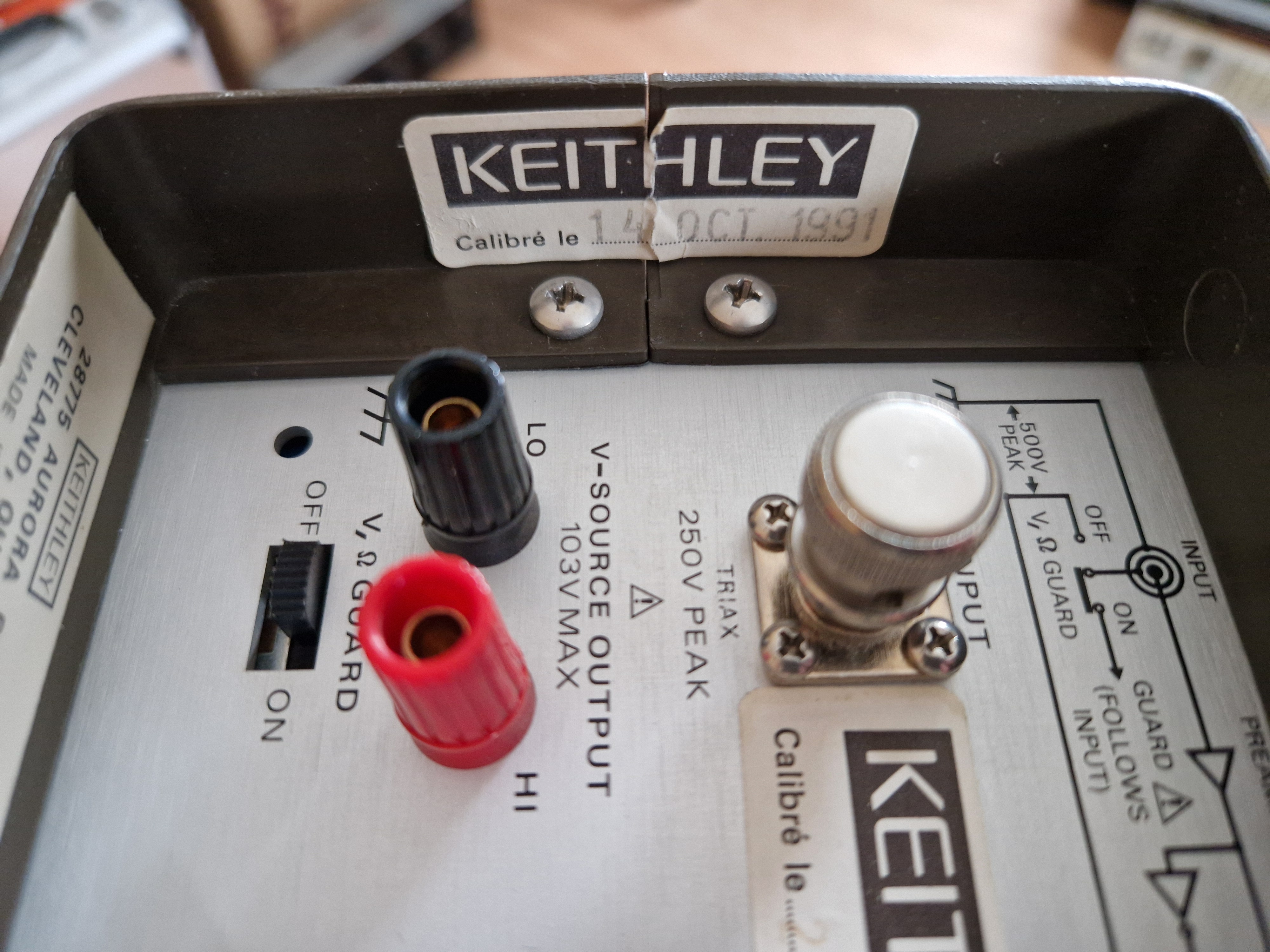
As you do, you take it apart! Before I opened the top case, this calibration sticker from 1991 was unbroken.


Some time before that sticker was applied, the meter was repaired, I can only assume, by Keithley themselves. At first glance, things looked OK inside.


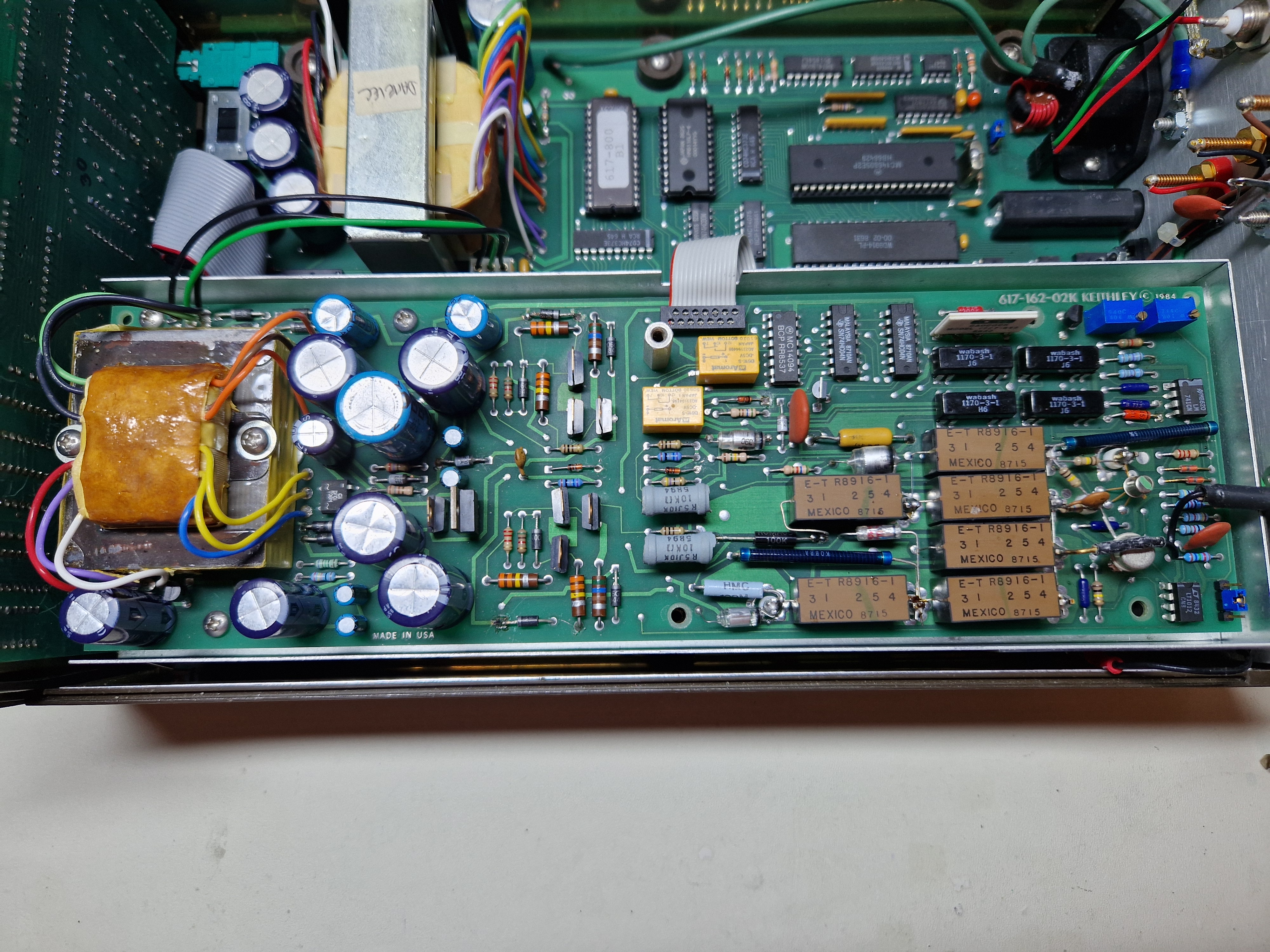
The analogue board is a revision K and the date codes on the various chips suggest it was manufactured in early 1987.
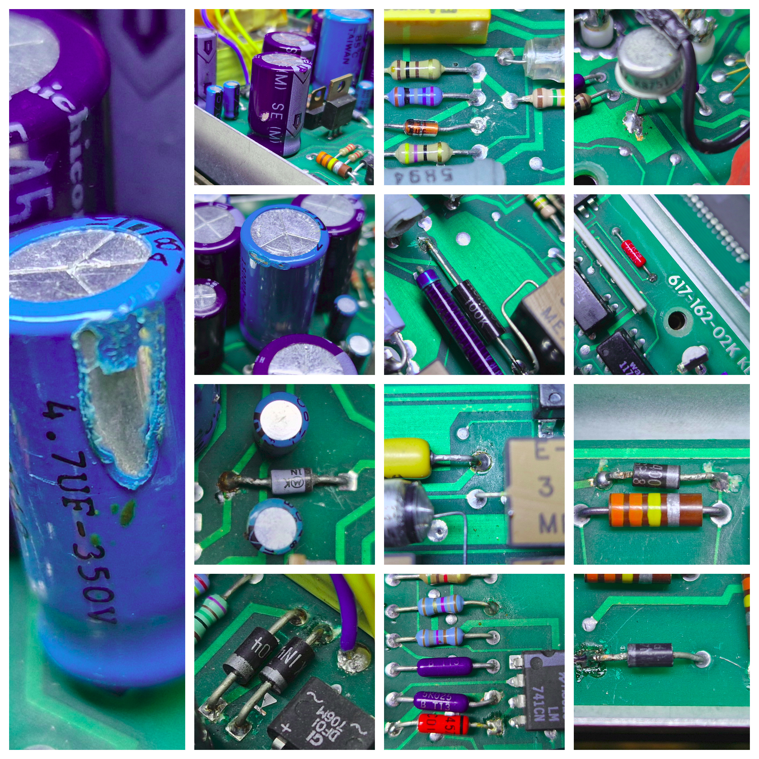
As I started looking closer at the analogue board though, I started noticing things. Bad things. Soldering iron burned insulation on electrolytic capacitors, Flux residue in both the power supply area and in the critical shielded circuitry. PCB damage and other evidence of a gorilla having been let loose on this incredibly sensitive piece of equipment.

If you have a sensitive disposition, you may want to avoid looking at the next image (it's even clickable for full size if you have a strong stomach).


I know there is a school of thought which says "cleaning flux residue off after a repair is worse than leaving it there" and I do understand that point of view for smaller and very limited repairs. Here though, many components have either been replaced, resoldered, chewed by metal eating cockroaches, etc and the residue around some of the fixes in the most sensitive area is just waiting for a very humid day.

The thing is, the meter is not unusually noisy, it needs calibration on all ranges as they all have a constant (by scale), slightly low reading against any of my standards. But it settles to a stable zero reading on the most sensitive ranges and it works on all functions and ranges showing no signs at all of any problems.

But now I know the injustices that have been perpetrated upon it. The flux spatter around all the repairs is significant. There are little dark brown, shiny spots all over the components and the PCB.  The burned insulation annoys me just as a matter of principle. The fact that this seems to have been done by the manufacturer themselves seems to go along with previous images in this thread where there are components with inexplicable pools of dark brown flux around where they enter the top side of the PCB. (I haven't dared remove the bottom cover yet for fear of seeing more horror!)

My OCD screams - "Take it apart, make it right!" The pragmatist in me says "It works, leave it alone."

What do you say?

« Last Edit: April 06, 2024, 08:27:45 pm by unseenninja »
 
The following users thanked this post: ch_scr

Offline Alex Nikitin

  • Super Contributor
  • ***
  • Posts: 1177
  • Country: gb
  • Femtoampnut and Tapehead.
    • A.N.T. Audio
Leave it as is if it works OK. Don't even think about cleaning the flux residue, you might easily ruin the unit. Ugly looks aside, I see no major problems and the Keithley may yet present you an opportunity to open more covers  ;) !

Cheers

Alex
 
The following users thanked this post: unseenninja

Offline unseenninja

  • Contributor
  • Posts: 18
  • Country: se
Good advice indeed. I shall restrain myself and leave it well alone!

I was very pleased to discover that Mouser sell H&S G_02330_HT cable by the metre. I trust cables made by me much more than I trust used, overpriced cables from eBay. They will most likely be far better than the Pomona cable I'm using at the moment.
 

Offline MiDi

  • Frequent Contributor
  • **
  • Posts: 600
  • Country: ua
I was very pleased to discover that Mouser sell H&S G_02330_HT cable by the metre. I trust cables made by me much more than I trust used, overpriced cables from eBay. They will most likely be far better than the Pomona cable I'm using at the moment.

The H&S G_02330_HT has PE insulation, which is not the best for low current measurements (leakage & DA).
Could be hard to find a matching triax connector for that outer diameter.
For reference: my DIY triax cable.
 

Offline Alex Nikitin

  • Super Contributor
  • ***
  • Posts: 1177
  • Country: gb
  • Femtoampnut and Tapehead.
    • A.N.T. Audio
The H&S G_02330_HT has PE insulation, which is not the best for low current measurements (leakage & DA).

Believe me, from experience, H&S uses a VERY GOOD PE, at room temperature even at 100V leakages are essentially unmeasurable for several meters of cable, plus noise levels from cable movements are very low, you almost can forget that you are dealing with femtoamps... .

Cheers

Alex
 
The following users thanked this post: vindoline, MiDi, ch_scr, unseenninja

Offline unseenninja

  • Contributor
  • Posts: 18
  • Country: se

The H&S G_02330_HT has PE insulation, which is not the best for low current measurements (leakage & DA).
Could be hard to find a matching triax connector for that outer diameter.
For reference: my DIY triax cable.

They do quote 100 TΩ insulation resistance in their data sheet. I'm hoping that matching connectors won't prove to be a problem, but I'll know more when I have the cable.

I was tempted by the Lemo cable that you used, but the 10 metre minimum order kind of put me off as I have no idea what I would do with the remaining 7 metres.
 

Offline Alex Nikitin

  • Super Contributor
  • ***
  • Posts: 1177
  • Country: gb
  • Femtoampnut and Tapehead.
    • A.N.T. Audio
I’m using H&S triaxial cable here, for 1.5m length  with two Pomona connectors, and 100V bias, the leakage is below 10fA (let’s say, it measures about 5fA and if I remove the voltage it shows about 3fA).

Cheers

Alex
 

Offline unseenninja

  • Contributor
  • Posts: 18
  • Country: se
Ah, so you got the Pomona 5056 connectors to mate with the G_02330_HT cable successfully?

The dimensions don't quite match, but I suspected it was possible to use them with the slightly thinner cable. I thought I'd use Marco Reps' method to heat up the outer insulation to get it stretch a bit more to accommodate the cone. A wrap of self vulcanising tape around the outer insulation should provide some strain relief when the connector is finally tightened.
 

Offline unseenninja

  • Contributor
  • Posts: 18
  • Country: se
For anyone looking to make their own cables, I can confirm that the Huber & Suhner G_02330_HT cable mates very nicely with the Pomona 5056 two lug triax connector. Just don't try to push the cone inside the cable's outer sheath like I did, it's enough to just engage the tip of the cone underneath the trimmed outer shield when you screw the plug together after fitting the pin and soldering the guard shield to the guard tube.

I also found the H&S cable really easy to work with. 20 AWG wire strippers will remove the the black, conductive layer cleanly from the inner dielectric and you can then strip the inner dielectric from the centre conductor with 22 AWG strippers. That way, you don't need to deform the inner dielectric or nick the inner conductor when you prepare the cable. For the outer shield and dielectric, a scalpel and care was sufficient. You'll need to cut along the outer sheath and dielectric from your cut as they will not pull off the cable.

Although I ordered 3m of cable from Mouser, they supplied me with three feet instead.  :palm:  Hopefully, by the time I try to order again, their pick and pack people might be more observant of the fact that it says, in capital letters, "Coaxial Cables SOLD IN METERS" on the product listing page!
 
 
The following users thanked this post: Kean

Offline BD1QMP

  • Contributor
  • Posts: 25
  • Country: cn
Today, I received my  Keithley 617 with very good condition. it was made in 1991 or 1992, and last cal time is 1999. when I power on it, on current and 2pA mode, no input, the read is change from 20 counts to 300. Now, I have work to do. ;D. maybe need clean the pcb first and change the capacitors .
 

Online Kosmic

  • Super Contributor
  • ***
  • Posts: 2531
  • Country: ca
Today, I received my  Keithley 617 with very good condition. it was made in 1991 or 1992, and last cal time is 1999. when I power on it, on current and 2pA mode, no input, the read is change from 20 counts to 300. Now, I have work to do. ;D. maybe need clean the pcb first and change the capacitors .

I would only attempt cleaning if the PCB is really dirty and changing capacitor if you really suspect them to be bad. Also always wear clean cloves when manipulating the input board.

But what is the problem exactly with your unit ? if it's simply a offset after removing Zero Check, check the manual page 7-5 chapter 7.4.8 "Input Offset Adjustment".
« Last Edit: Yesterday at 12:57:47 pm by Kosmic »
 

Offline HighVoltage

  • Super Contributor
  • ***
  • Posts: 5473
  • Country: de
Today, I received my  Keithley 617 with very good condition. it was made in 1991 or 1992, and last cal time is 1999. when I power on it, on current and 2pA mode, no input, the read is change from 20 counts to 300. Now, I have work to do. ;D. maybe need clean the pcb first and change the capacitors .

Maybe just place a short on the input and watch it again.
Some charge can caused this,
There are 3 kinds of people in this world, those who can count and those who can not.
 

Offline Alex Nikitin

  • Super Contributor
  • ***
  • Posts: 1177
  • Country: gb
  • Femtoampnut and Tapehead.
    • A.N.T. Audio
Maybe just place a short on the input and watch it again.
Some charge can caused this,

You don't place a short on the input of a transimpedance amplifier (such as an electrometer in the current measuring mode), you use a screening cap over the input (or just a bit of an aluminium foil) !

Cheers

Alex
« Last Edit: Yesterday at 10:06:15 pm by Alex Nikitin »
 
The following users thanked this post: HighVoltage, ch_scr

Offline HighVoltage

  • Super Contributor
  • ***
  • Posts: 5473
  • Country: de

You don't place a short on the input of a transimpedance amplifier (such as an electrometer in the current measuring mode), you use a screening cap over the input (or just a bit of an aluminium foil) !

Cheers

Alex
Very true, my mind was somewhere else, thanks for pointing this out!
There are 3 kinds of people in this world, those who can count and those who can not.


Share me

Digg  Facebook  SlashDot  Delicious  Technorati  Twitter  Google  Yahoo
Smf