Author Topic: Most accurate signal generator  (Read 11844 times)

0 Members and 1 Guest are viewing this topic.

Offline loop123Topic starter

  • Frequent Contributor
  • **
  • !
  • Posts: 297
  • Country: ca
Most accurate signal generator
« on: March 25, 2024, 08:40:00 am »
2083976-0


I have 2 china made signal or function generators that are junk. It can't even tell the amplitude. What is the most accurate signal generator ever but also inexpensive? Range is audio range of 0 to 20000Hz and voltage from 0 to 5V or so. It has to be accurate in 1/100000th or output say 1.00001 V or has frequency accuracy of say 5000.00000 Hz and can output in rms or peak to peak. It has to be stand alone unit because I don't want to buy a $5000 oscilloscope just to use the function generator. What have you encountered or used? Thank you.


Online Aldo22

  • Frequent Contributor
  • **
  • Posts: 695
  • Country: ch
Re: Most accurate signal generator
« Reply #1 on: March 25, 2024, 09:27:40 am »
What do you mean by "inexpensive"?
I'm no expert, but I doubt that 10 microvolts of amplitude "accuracy" and "inexpensive" go together.
 
The following users thanked this post: David Aurora, egonotto, 807, Tom45, Anthocyanina, 5U4GB

Offline HalFoster

  • Regular Contributor
  • *
  • Posts: 211
  • Country: us
Re: Most accurate signal generator
« Reply #2 on: March 25, 2024, 09:30:53 am »
First, an $5K oscilloscope built in generator would not even be close.  The frequency accuracy would be met by most any OCXO, and by many of the better ones with a standard oscillator.  The output will be specified in dBm at 50R, not in volts, and would be around -87 dBm for .00001 VRMS.  A very good, affordable choice would be a HP 3335A.
--- If it isn't broken... Fix it until it is ---
 

Online Antonio90

  • Frequent Contributor
  • **
  • Posts: 295
  • Country: es
Re: Most accurate signal generator
« Reply #3 on: March 25, 2024, 09:37:46 am »
10uV is inside the noise specs of really good linear PSUs. You cannot measure it with any reasonable certainty using cheap DMMs (ACV).
A Siglent SDG2042X (€475+VAT) will outperform any DSO's integrated AWG, and the specified amplitude accuracy is ±(1%+1mV), so 1V ± 0.02V (at 10KHz, and the uncertainty goes up with frequency). 1.00001V means 0.001% or 10ppm accuracy.
I don't think it's happening anytime soon. Although there might be audio analyzers with signal generators that reach those levels, a general purpose AWG will not. As a matter of fact, the resolution you asked for could not be resolved even with 16 bit ENOB, as that would be 65,536 steps, and around 15uV for a 1V peak to peak signal.
« Last Edit: March 25, 2024, 10:10:44 am by Antonio90 »
 
The following users thanked this post: egonotto

Offline jonpaul

  • Super Contributor
  • ***
  • Posts: 3366
  • Country: fr
Re: Most accurate signal generator
« Reply #4 on: March 25, 2024, 10:41:18 am »
Audio Precision, GenRad, Prisim, TEK SG505

China junk is not to be trusted for any measurement

j
Jean-Paul  the Internet Dinosaur
 

Offline ebastler

  • Super Contributor
  • ***
  • Posts: 6510
  • Country: de
Re: Most accurate signal generator
« Reply #5 on: March 25, 2024, 10:53:21 am »
It has to be accurate in 1/100000th or output say 1.00001 V or has frequency accuracy of say 5000.00000 Hz

You mean an amplitude accuracy of 10-5, so 1 V +- 0.00001 V?
And a frequency accuracy of 2 * 10-9, so 5000 Hz +- 0.00001 Hz?

I am not sure which commercial instruments would offer that. Seeing you mention "inexpensive", I am quite sure you would not want to pay for them, if they exist. And frankly, I would be very surprised if you need these specs. What is the application which requires that level of accuracy?

Edit: You might be confusing accuracy (to what extent can you trust the exact value?) with resolution (what are the smallest relative changes the display shows you?). And even when talking about resolution, you probably don't need the values you mention. 0.00001 Hz is one oscillation every 100 000 seconds, i.e. 27 hours! And 0.00001 V = 10 µV is quite challenging to control and measure on its own -- let alone when it sits on top of a 1V signal.
« Last Edit: March 25, 2024, 11:24:35 am by ebastler »
 
The following users thanked this post: Performa01, croma641, egonotto, 807, newbrain, Anthocyanina

Online themadhippy

  • Super Contributor
  • ***
  • Posts: 2583
  • Country: gb
Re: Most accurate signal generator
« Reply #6 on: March 25, 2024, 11:33:40 am »
Quote
Most accurate signal generator
Brian,the blind piano tuner i used to know.
 

Offline DimitriP

  • Super Contributor
  • ***
  • Posts: 1308
  • Country: us
  • "Best practices" are best not practiced.© Dimitri
Re: Most accurate signal generator
« Reply #7 on: March 25, 2024, 12:13:08 pm »
Quote
Most accurate signal generator
Brian,the blind piano tuner i used to know.

That would be a frequency counter....not a generator :)
   If three 100  Ohm resistors are connected in parallel, and in series with a 200 Ohm resistor, how many resistors do you have? 
 
The following users thanked this post: egonotto, Fungus

Offline DimitriP

  • Super Contributor
  • ***
  • Posts: 1308
  • Country: us
  • "Best practices" are best not practiced.© Dimitri
Re: Most accurate signal generator
« Reply #8 on: March 25, 2024, 12:15:57 pm »
Quote
What have you encountered or used?
For audio, using a USB audio interface and software will be "cheaper" than buying stand alone instruments.

But more importantly, what are you trying to get done?
   If three 100  Ohm resistors are connected in parallel, and in series with a 200 Ohm resistor, how many resistors do you have? 
 

Online Antonio90

  • Frequent Contributor
  • **
  • Posts: 295
  • Country: es
Re: Most accurate signal generator
« Reply #9 on: March 25, 2024, 12:23:07 pm »
Quote
Most accurate signal generator
Brian,the blind piano tuner i used to know.

That would be a frequency counter....not a generator :)
Maybe he sang really really in tune.
 
The following users thanked this post: 807

Online Fungus

  • Super Contributor
  • ***
  • Posts: 16679
  • Country: 00
Re: Most accurate signal generator
« Reply #10 on: March 25, 2024, 12:34:21 pm »
Signal generators aren't cheap. Those Aliexpress gadgets are toys, as you've seen, they output waves but that's about it.

I think the cheapest signal generator worth owning is the Unit-T UTG932e. That's your baseline for price.

It has to be accurate in 1/100000th or output say 1.00001 V

Maybe you mean the smallest change you can make in the output, not "accuracy"?

1/100000th is approx. 17 bits so you'd need a generator with 18 bits (or more) to achieve that.

If you really meant "accuracy" then I don't think that exists in a signal generator. If it does, you won't want to pay for it.

PS: You'll definitely get a better answer if you say what you're trying to achieve.


Online Fungus

  • Super Contributor
  • ***
  • Posts: 16679
  • Country: 00
Re: Most accurate signal generator
« Reply #11 on: March 25, 2024, 12:35:48 pm »
For audio, using a USB audio interface and software will be "cheaper" than buying stand alone instruments.

But getting an accurate output voltage won't be easy.
 

Online Antonio90

  • Frequent Contributor
  • **
  • Posts: 295
  • Country: es
Re: Most accurate signal generator
« Reply #12 on: March 25, 2024, 12:58:20 pm »
Signal generators aren't cheap. Those Aliexpress gadgets are toys, as you've seen, they output waves but that's about it.

I think the cheapest signal generator worth owning is the Unit-T UTG932e. That's your baseline for price.

It has to be accurate in 1/100000th or output say 1.00001 V

Maybe you mean the smallest change you can make in the output, not "accuracy"?

1/100000th is approx. 17 bits so you'd need a generator with 18 bits (or more) to achieve that.

If you really meant "accuracy" then I don't think that exists in a signal generator. If it does, you won't want to pay for it.

PS: You'll definitely get a better answer if you say what you're trying to achieve.
17 bits ENOB looks to me more like 22-24 bits. Cheap audio interfaces can do that resolution-wise, but not accuracy-wise. It would need high frequency stability, so some kind of hacked-in OCXO or TCXO, and then a low noise amplifier to get the 5Vpp.


Offline loop123Topic starter

  • Frequent Contributor
  • **
  • !
  • Posts: 297
  • Country: ca
Re: Most accurate signal generator
« Reply #13 on: March 25, 2024, 01:43:02 pm »
Signal generators aren't cheap. Those Aliexpress gadgets are toys, as you've seen, they output waves but that's about it.

I think the cheapest signal generator worth owning is the Unit-T UTG932e. That's your baseline for price.

It has to be accurate in 1/100000th or output say 1.00001 V

Maybe you mean the smallest change you can make in the output, not "accuracy"?

1/100000th is approx. 17 bits so you'd need a generator with 18 bits (or more) to achieve that.

If you really meant "accuracy" then I don't think that exists in a signal generator. If it does, you won't want to pay for it.

PS: You'll definitely get a better answer if you say what you're trying to achieve.

Since Im not even sure what amplitude my 2 china signal generator is outputting. I just want something where you can input the voltage and frequency in the led and it would produce accurate output. Just accuracy, not about resolution. For general use for example testing any amplifier or ADC. So what sub $200 is accurate enough?
 

Offline ebastler

  • Super Contributor
  • ***
  • Posts: 6510
  • Country: de
Re: Most accurate signal generator
« Reply #14 on: March 25, 2024, 01:50:13 pm »
So what sub $200 is accurate enough?

Accurate enough for what? What do you want to do with the generator? You mention amplifiers and ADCs -- are these just for audio use, or something more specialised? Do you want to develop audio amplifiers, or repair them? What specifications do these amplifiers have, or what do you have in mind? etc.

As a general comment: It's not "just accuracy". Accuracy is harder to achieve than resolution. E.g. my 3 meter tape measure easily has 1 mm resolution -- I can clearly see the scale lines every mm. But is it accurate to 1 mm? Maybe not; it might actually be 3.002 meters long instead of 3 meters.
 
The following users thanked this post: Tom45, Aldo22

Online Fungus

  • Super Contributor
  • ***
  • Posts: 16679
  • Country: 00
Re: Most accurate signal generator
« Reply #15 on: March 25, 2024, 02:12:42 pm »
For general use for example testing any amplifier or ADC. So what sub $200 is accurate enough?

For Audio amplifiers? The Unit-T UTG932e is plenty accurate enough.

(and it's the only sub-$200 generator worth considering, so if that's your budget then...  :-// )
 

Online radiolistener

  • Super Contributor
  • ***
  • Posts: 3386
  • Country: ua
Re: Most accurate signal generator
« Reply #16 on: March 25, 2024, 02:25:32 pm »
I think SDG6022X signal accuracy should be good enough for amateur needs.
https://siglentna.com/product/sdg6022x/

But its performance is not the best. So, if you want better performance, there is may be a sense to look for some specialized signal generator for your needs?

What do you mean when talking "most accurate"? Less noise / less spurs / high dynamic range? 

If you're interested in precise amplitude, then there is a sense to look for RF generator. They have pretty clean sine output and allows to setup calibrated amplitude. But note, all signal generators have fixed output impedance, usually 50 Ω (sometimes there is a switch between 50 Ω and 600 Ω). And if your load is not 50 Ω, then you're needs to recalculate amplitude, that is normal and expected behavior.
« Last Edit: March 25, 2024, 02:31:16 pm by radiolistener »
 

Online PA0PBZ

  • Super Contributor
  • ***
  • Posts: 5129
  • Country: nl
Re: Most accurate signal generator
« Reply #17 on: March 25, 2024, 02:32:31 pm »
Get yourself a 2nd hand Wavetek 98, 8 digits frequency resolution, 4 digits amplitude, can be had for $100.

https://www.testmart.com/webdata/mfr_pdfs/FLUPR/WAV_98.pdf
Keyboard error: Press F1 to continue.
 
The following users thanked this post: Protegimus

Offline Electro Fan

  • Super Contributor
  • ***
  • Posts: 3199
Re: Most accurate signal generator
« Reply #18 on: March 25, 2024, 02:46:23 pm »
Signal generators aren't cheap. Those Aliexpress gadgets are toys, as you've seen, they output waves but that's about it.

I think the cheapest signal generator worth owning is the Unit-T UTG932e. That's your baseline for price.

It has to be accurate in 1/100000th or output say 1.00001 V

Maybe you mean the smallest change you can make in the output, not "accuracy"?

1/100000th is approx. 17 bits so you'd need a generator with 18 bits (or more) to achieve that.

If you really meant "accuracy" then I don't think that exists in a signal generator. If it does, you won't want to pay for it.

PS: You'll definitely get a better answer if you say what you're trying to achieve.

Since Im not even sure what amplitude my 2 china signal generator is outputting. I just want something where you can input the voltage and frequency in the led and it would produce accurate output. Just accuracy, not about resolution. For general use for example testing any amplifier or ADC. So what sub $200 is accurate enough?

The Uni-T UTG generator models are good baseline models to consider as you look at your options.

https://storage.googleapis.com/uni-tdocuments/UTG900E_Series_User_Manual_REV2.pdf

Not 100% sure about your objectives but if you want to build something that is still more accurate and flexible you might consider finding a solid signal generator that has a 10 MHz Reference Input, such as the Siglent SDG1032X, but this alone will set you back about $350.

https://siglentna.com/wp-content/uploads/dlm_uploads/2022/06/SDG1000X_UserManual_UM0201X-E01E.pdf
See on page 4:  10 MHz Clock Input/Output

Then, for about $100-200 you can add a GPSDO, such as some model made by BG7TBL on eBay.

https://www.ebay.com/itm/296236063029?itmmeta=01HSTZB4K00HP2PPEAZA5PW64B&hash=item44f90b9935:g:VRcAAOSw~dFl1E5q&itmprp=enc%3AAQAJAAAA4MtrtctaRljoQ7FmzGN3WVi2l6pgv1PrjLbi0NuhSM6pql7j7%2FqoyB89uRCzMNoK1x7q2qqF8jDl6XJbPSmvasas2NC%2FLGC0n8zpFPfTsgCcPsqYTXZkGMCqsiPEnaxCA5%2BNPzBLAqu7SsAm6%2BedWsAY9%2Ftwa2Rs8%2BCBJDfSr7q5nGRd2PczloEG%2FdH%2BnABJG0aix8aCPaSfPNyhsqMeVzFRv4IjEnkS3XXZtPivapJnUvtBKsPFXodPxHLgBkeH8I%2Bih7gUaWTsOl1YSwDAFR%2F3%2BbmvOOXwfYo4aadWujoH%7Ctkp%3ABk9SR8bJrN_OYw

The GPSDO 10 MHz output connects to the 10 MHz input on the back of the Siglent generator.

Altogether this will set you back about $550 but you should be good to go on flexible and accurate signal frequency management.

Or you could start with the Siglent and see if you want/need the GPSDO.

Hint:  what you are looking for is something with a good clock source.
Maybe study oscillators:
https://blog.bliley.com/quartz-crystal-oscillators-guide-ocxo-tcxo-vcxo-clocks


« Last Edit: March 25, 2024, 03:04:48 pm by Electro Fan »
 

Online radiolistener

  • Super Contributor
  • ***
  • Posts: 3386
  • Country: ua
Re: Most accurate signal generator
« Reply #19 on: March 25, 2024, 02:55:26 pm »
It has to be accurate in 1/100000th or output say 1.00001 V or has

if you want to setup 1 V or 0.00001 V, RF generator can do that, it can even do 0.000001 V or 0.0000001 V.
But it doing it with logarithmic scale, while 1.00001 V requires linear scale with 0.00001 V resolution.
I didn't hear that such generators exists.

frequency accuracy of say 5000.00000 Hz

That is 0.002 ppm. Using rubidium frequency standard it can be possible.

But I'm not sure what is the use case for so precise signal?  :o
« Last Edit: March 25, 2024, 02:56:57 pm by radiolistener »
 

Online bdunham7

  • Super Contributor
  • ***
  • Posts: 7860
  • Country: us
Re: Most accurate signal generator
« Reply #20 on: March 25, 2024, 03:01:00 pm »
Since Im not even sure what amplitude my 2 china signal generator is outputting. I just want something where you can input the voltage and frequency in the led and it would produce accurate output. Just accuracy, not about resolution. For general use for example testing any amplifier or ADC. So what sub $200 is accurate enough?

Any reasonable DDS-based AWG (arbitrary waveform generator) is probably what you are looking for, but your stated accuracy requirements are not as easily achieved.  I'd suggest not just randomly picking numbers when you make a request like that and instead figure out what accuracy you really need.  For testing an audio amplifier a 0.3dB accuracy, which corresponds to about 3% voltage error, should be good enough and is easily achievable by inexpensive AWGs.  For testing an ADC, that depends on exactly what testing you are doing.  For frequency accuracy with a sine wave, it should be easy to achieve <50ppm error, but you seem to be implying that you want an accuracy of better than 1 in 500 million, or 2ppb, which would be unreasonably difficult for an inexpensive AWG.

IDK about under $200, but the Siglent SDG810 is $239 and seems to do what you need (but not what you stated originally).

https://siglentna.com/wp-content/uploads/dlm_uploads/2017/10/SDG800_DataSheet_DS02008-E02D.pdf

Other more expensive AWGs may have better specs if you actually need them.  The Siglent SDG2042X that I have is roughly 1ppm and 0.1dB.  Getting better than that starts to cost real money.
 

A 3.5 digit 4.5 digit 5 digit 5.5 digit 6.5 digit 7.5 digit DMM is good enough for most people.
 

Offline voltsandjolts

  • Supporter
  • ****
  • Posts: 2300
  • Country: gb
Re: Most accurate signal generator
« Reply #21 on: March 25, 2024, 03:37:15 pm »
But I'm not sure what is the use case for so precise signal?  :o

The OP is "experimenting" in electrical signals of the human body, see other nonsense threads.
 
The following users thanked this post: egonotto, newbrain

Offline nctnico

  • Super Contributor
  • ***
  • Posts: 26907
  • Country: nl
    • NCT Developments
Re: Most accurate signal generator
« Reply #22 on: March 25, 2024, 04:50:05 pm »
Cheap and super accurate don't go well together. When you need accuracy, you'll need a levelled signal generator like the ones being used to calibrate oscilloscopes. There is an HP / Agilent generator model with accurate outputs but I can't remember the model number.
There are small lies, big lies and then there is what is on the screen of your oscilloscope.
 

Offline switchabl

  • Frequent Contributor
  • **
  • Posts: 440
  • Country: de
Re: Most accurate signal generator
« Reply #23 on: March 25, 2024, 05:17:45 pm »
There is an HP / Agilent generator model with accurate outputs but I can't remember the model number.

You may be thinking of the 3245A Universal Source. The headline spec for AC amplitude accuracy is 0.4% which would be roughly on par with an APx555.

The prize for actual "most accurate signal generator" probably goes to one of the JAWS (Josephson Arbitrary Waveform Synthesizer) developed by several national metrology institutes.
 
The following users thanked this post: nctnico, egonotto, bdunham7

Online Fungus

  • Super Contributor
  • ***
  • Posts: 16679
  • Country: 00
Re: Most accurate signal generator
« Reply #24 on: March 25, 2024, 05:28:08 pm »
The OP is "experimenting" in electrical signals of the human body, see other nonsense threads.

Oh... I did wonder about somebody posting those requirements along with a picture of a FNIRSI.
 

Online bdunham7

  • Super Contributor
  • ***
  • Posts: 7860
  • Country: us
Re: Most accurate signal generator
« Reply #25 on: March 25, 2024, 06:00:19 pm »
The prize for actual "most accurate signal generator" probably goes to one of the JAWS (Josephson Arbitrary Waveform Synthesizer) developed by several national metrology institutes.

Note that even the $550,000 JAWS 2V system would not quite meet the OP's initial accuracy requirement of 1 part in 100,000 over the audio range.   :palm: 

see the top of p. 3

https://www.nist.gov/system/files/documents/2023/01/10/6011.pdf
A 3.5 digit 4.5 digit 5 digit 5.5 digit 6.5 digit 7.5 digit DMM is good enough for most people.
 
The following users thanked this post: egonotto

Online DaneLaw

  • Frequent Contributor
  • **
  • Posts: 450
  • Country: dk
Re: Most accurate signal generator
« Reply #26 on: March 25, 2024, 06:23:43 pm »
The prize for actual "most accurate signal generator" probably goes to one of the JAWS (Josephson Arbitrary Waveform Synthesizer) developed by several national metrology institutes.

Note that even the $550,000 JAWS 2V system would not quite meet the OP's initial accuracy requirement of 1 part in 100,000 over the audio range.   :palm: 

see the top of p. 3

https://www.nist.gov/system/files/documents/2023/01/10/6011.pdf

Then what would?
Let's help OP get his "most accurate signal generator" that matches his criteria.
A custom jobby build to tolerances by a big brand name, so OP can exchange his TC3 Fnirsi and his 15 USD FG-100 for one of those..
Accuracy matters..!
 
The following users thanked this post: egonotto

Offline loop123Topic starter

  • Frequent Contributor
  • **
  • !
  • Posts: 297
  • Country: ca
Re: Most accurate signal generator
« Reply #27 on: March 25, 2024, 09:11:30 pm »
I think SDG6022X signal accuracy should be good enough for amateur needs.
https://siglentna.com/product/sdg6022x/

But its performance is not the best. So, if you want better performance, there is may be a sense to look for some specialized signal generator for your needs?

What do you mean when talking "most accurate"? Less noise / less spurs / high dynamic range? 

If you're interested in precise amplitude, then there is a sense to look for RF generator. They have pretty clean sine output and allows to setup calibrated amplitude. But note, all signal generators have fixed output impedance, usually 50 Ω (sometimes there is a switch between 50 Ω and 600 Ω). And if your load is not 50 Ω, then you're needs to recalculate amplitude, that is normal and expected behavior.

The use is specifically to test the E1DC Cosmos ADC to see if for example it's 0dB corresponds to 1.7V or 1.8V in its lowest setting (with best dynamic range). Just to test its overall accuracy. My present 2 signal generators don't even produce output where I can be certain it's 1V or 1.5V for example. So I need one where I can produce accurate 1.7V or 1.8V to see which voltage would clip it and establish the baseline because different units vary according to the manufacturer. I didn't know choosing signal generator is that complicated that is why didn't post the entire picture below in the original message. In the following is the -128dB noise floor of my E1DA I tested using REW RTA. My budget for the stand alone signal generator is less than $200. Please recommend which one specifically I should get knowing my requirements. Thanks.

https://e1dashz.wixsite.com/index/cosmos-adc

2084516-0

2084522-1

2084528-2


Online bdunham7

  • Super Contributor
  • ***
  • Posts: 7860
  • Country: us
Re: Most accurate signal generator
« Reply #28 on: March 25, 2024, 09:30:50 pm »
I didn't know choosing signal generator is that complicated that is why didn't post the entire picture below in the original message. In the following is the -128dB noise floor of my E1DA I tested using REW RTA. My budget for the stand alone signal generator is less than $200. Please recommend which one specifically I should get knowing my requirements. Thanks.

The models I mentioned would more than suffice but they blow your budget.  The cheap and cheerful FY6900 will mostly likely work just fine, but I couldn't personally guarantee it without testing the unit first.

https://www.aliexpress.us/item/3256802190692386.html
A 3.5 digit 4.5 digit 5 digit 5.5 digit 6.5 digit 7.5 digit DMM is good enough for most people.
 

Offline nctnico

  • Super Contributor
  • ***
  • Posts: 26907
  • Country: nl
    • NCT Developments
Re: Most accurate signal generator
« Reply #29 on: March 25, 2024, 09:37:03 pm »
I didn't know choosing signal generator is that complicated that is why didn't post the entire picture below in the original message. In the following is the -128dB noise floor of my E1DA I tested using REW RTA. My budget for the stand alone signal generator is less than $200. Please recommend which one specifically I should get knowing my requirements. Thanks.

The models I mentioned would more than suffice but they blow your budget.  The cheap and cheerful FY6900 will mostly likely work just fine, but I couldn't personally guarantee it without testing the unit first.

https://www.aliexpress.us/item/3256802190692386.html
The UNI-T UTG932E will also work and is generally available from local distributors which helps with warranty issues (or returning it if it turns out to be no good). I have no hands-on experience with the UNI-T UTG932E or the FY6900, but the UTG932E looks like it has a better user interface as well.

But either will be way better compared to the FG-100 according to this review: https://hackaday.com/2018/05/17/review-fg-100-dds-function-generator/ Spoiler alert: the FG-100 is a waste of money.
« Last Edit: March 25, 2024, 09:40:21 pm by nctnico »
There are small lies, big lies and then there is what is on the screen of your oscilloscope.
 

Online Fungus

  • Super Contributor
  • ***
  • Posts: 16679
  • Country: 00
Re: Most accurate signal generator
« Reply #30 on: March 26, 2024, 12:02:21 am »
The UNI-T UTG932E will also work and is generally available from local distributors which helps with warranty issues (or returning it if it turns out to be no good).

I got mine on Amazon.

I have no hands-on experience with the UNI-T UTG932E

It works well enough. A lot of EEVBLOG owners have one.
 

Offline loop123Topic starter

  • Frequent Contributor
  • **
  • !
  • Posts: 297
  • Country: ca
Re: Most accurate signal generator
« Reply #31 on: March 26, 2024, 01:16:20 am »
i only need sine wave at 1.8V. Arent there cheap modules where it just produces constant 1.8V sine wave? How to build one if none offered. Also why is it hard to make accurate sine wave generators. Dont you just need a crystal for clock. Is it not a crystal is very accurate like used in processor. Its not like you have to synchronize it with the frequency of pulsar star. Are you saying crystals used in clocks in processor or adc are dirty or not pure so the output from mechanical oscillators are not unform??
 

Online Fungus

  • Super Contributor
  • ***
  • Posts: 16679
  • Country: 00
Re: Most accurate signal generator
« Reply #32 on: March 26, 2024, 02:39:38 am »
i only need sine wave at 1.8V. Arent there cheap modules where it just produces constant 1.8V sine wave? How to build one if none offered.

Get something with more than 1.8V, put a potentiometer across the output so you can dial a voltage, and look at it on an oscilloscope?
 

Offline Bud

  • Super Contributor
  • ***
  • Posts: 6912
  • Country: ca
Re: Most accurate signal generator
« Reply #33 on: March 26, 2024, 04:50:43 am »
Also why is it hard to make accurate sine wave generators. Dont you just need a crystal for clock. Is it not a crystal is very accurate like used in processor.
Processors do not give shit about clock accuracy.
Quote
Its not like you have to synchronize it with the frequency of pulsar star.
With your requirements it seems this is what you have to do, i.e. use a GPS disciplinned oscillator, or a rubidium oscillator. Do your research how to build them or how much a commercially built one may cost.

Quote
  Are you saying crystals used in clocks in processor or adc are dirty or not pure so the output from mechanical oscillators are not unform??
Crystals have large (compare to your requirements) temperature, tolerance and aging drift. To satisfy your requirements you need a different frequency reference 1000 times better. Crystals will change frequency when you look wrong at them.
Facebook-free life and Rigol-free shack.
 
The following users thanked this post: egonotto

Offline loop123Topic starter

  • Frequent Contributor
  • **
  • !
  • Posts: 297
  • Country: ca
Re: Most accurate signal generator
« Reply #34 on: March 26, 2024, 05:59:05 am »
Also why is it hard to make accurate sine wave generators. Dont you just need a crystal for clock. Is it not a crystal is very accurate like used in processor.
Processors do not give shit about clock accuracy.
Quote
Its not like you have to synchronize it with the frequency of pulsar star.
With your requirements it seems this is what you have to do, i.e. use a GPS disciplinned oscillator, or a rubidium oscillator. Do your research how to build them or how much a commercially built one may cost.

Quote
  Are you saying crystals used in clocks in processor or adc are dirty or not pure so the output from mechanical oscillators are not unform??
Crystals have large (compare to your requirements) temperature, tolerance and aging drift. To satisfy your requirements you need a different frequency reference 1000 times better. Crystals will change frequency when you look wrong at them.


You mean its difficult even to produce accurate 1.8V sine wave?  Is the voltage or sine wave more difficult to make or which one is more affected by a crystal/clock? usually what are the errors in crystal just to have an idea? but then if crystals vary how do wifi or cell phone even connect?
 

Online Anthocyanina

  • Frequent Contributor
  • **
  • Posts: 340
  • Country: 00
  • The Sara
Re: Most accurate signal generator
« Reply #35 on: March 26, 2024, 06:19:48 am »
Also why is it hard to make accurate sine wave generators. Dont you just need a crystal for clock. Is it not a crystal is very accurate like used in processor.
Processors do not give shit about clock accuracy.
Quote
Its not like you have to synchronize it with the frequency of pulsar star.
With your requirements it seems this is what you have to do, i.e. use a GPS disciplinned oscillator, or a rubidium oscillator. Do your research how to build them or how much a commercially built one may cost.

Quote
  Are you saying crystals used in clocks in processor or adc are dirty or not pure so the output from mechanical oscillators are not unform??
Crystals have large (compare to your requirements) temperature, tolerance and aging drift. To satisfy your requirements you need a different frequency reference 1000 times better. Crystals will change frequency when you look wrong at them.


You mean its difficult even to produce accurate 1.8V sine wave?  Is the voltage or sine wave more difficult to make or which one is more affected by a crystal/clock? usually what are the errors in crystal just to have an idea? but then if crystals vary how do wifi or cell phone even connect?

making a sine wave is ridiculously easy, making a sine wave 1.8v in amplitude is easy, making a sine wave within the frequency range you need is also easy, but, making it precisely 1.8v to the 10uV of deviation you want, and within the 10uHz you want, that's where it approaches the physically impossible if not already there, and absolutely impossible for 200$, but also it is very unlikely that you (or most people) need a signal source with those specifications.

crystal frequency can vary depending on temperature, pressure on it because of minor PCB bends and how the materials bend differently due to temperature changes, other factors can also influence the frequency stability of the crystal, maybe minor defects in the crystal structure itself, in the manufacture process...

those radio systems can connect because they have a tolerance range that accounts for the physically, practically and economically realizable components and designs.

and about the voltage stability, a big reason why AM radio sounds so bad when compared to FM radio, noise is everywhere, and gets everywhere, and you see that in the form of variations in amplitude. if you capture a single period of a sine wave, it will not be perfectly sinusoidal, but you'll see it's a bit "frizzy", its amplitude at any x point deviating slightly from what you'd get from calculating sin(x)
« Last Edit: March 26, 2024, 06:33:37 am by Anthocyanina »
 
The following users thanked this post: egonotto

Offline loop123Topic starter

  • Frequent Contributor
  • **
  • !
  • Posts: 297
  • Country: ca
Re: Most accurate signal generator
« Reply #36 on: March 26, 2024, 06:48:42 am »
Quote
You mean its difficult even to produce accurate 1.8V sine wave?  Is the voltage or sine wave more difficult to make or which one is more affected by a crystal/clock? usually what are the errors in crystal just to have an idea? but then if crystals vary how do wifi or cell phone even connect?

making a sine wave is ridiculously easy, making a sine wave 1.8v in amplitude is easy, making a sine wave within the frequency range you need is also easy, but, making it precisely 1.8v to the 10uV of deviation you want, and within the 10uHz you want, that's where it approaches the physically impossible if not already there, and absolutely impossible for 200$, but also it is very unlikely that you (or most people) need a signal source with those specifications.

crystal frequency can vary depending on temperature, pressure on it because of minor PCB bends and how the materials bend differently due to temperature changes, other factors can also influence the frequency stability of the crystal, maybe minor defects in the crystal structure itself, in the manufacture process...

those radio systems can connect because they have a tolerance range that accounts for the physically, practically and economically realizable components and designs.

and about the voltage stability, a big reason why AM radio sounds so bad when compared to FM radio, noise is everywhere, and gets everywhere, and you see that in the form of variations in amplitude. if you capture a single period of a sine wave, it will not be perfectly sinusoidal, but you'll see it's a bit "frizzy", its amplitude at any x point deviating slightly from what you'd get from calculating sin(x)

No. I just wrote 1.00001V to drive the point that it should not be 1.2V or 0.9V but exactly 1V. It doesn't have to be 1.00001V but only 1.01 volt for example. It is enough. With that clarified. I just need a sine wave generator that can produce 1.8V (error of 1.801V) and 5000Hz (not 5001Hz or 4999 Hz). How do you build them anyway? Since I'd rarely use it. My budget for finished product (I want ot avoid building it) is lower to $50..
 

Offline ebastler

  • Super Contributor
  • ***
  • Posts: 6510
  • Country: de
Re: Most accurate signal generator
« Reply #37 on: March 26, 2024, 07:00:48 am »
No. I just wrote 1.00001V to drive the point that it should not be 1.2V or 0.9V but exactly 1V. It doesn't have to be 1.00001V but only 1.01 volt for example. It is enough. With that clarified. I just need a sine wave generator that can produce 1.8V (error of 1.801V) and 5000Hz (not 5001Hz or 4999 Hz). How do you build them anyway? Since I'd rarely use it. My budget for finished product (I want ot avoid building it) is lower to $50..

You are still very unclear regarding the accuracy you need (or want). So what is the voltage error you allow -- 0.01 V or 0.001 V? And what is the frequency error you allow -- less than 1 Hz, but how much can you tolerate? 0.1 Hz?

And you are very unclear regarding the budget. If it is $50, why did you tell us $200 before?
 
The following users thanked this post: egonotto, 807

Offline ebastler

  • Super Contributor
  • ***
  • Posts: 6510
  • Country: de
Re: Most accurate signal generator
« Reply #38 on: March 26, 2024, 07:14:59 am »
Here's an idea, if you are on a low budget: Keep your cheap generator, but buy a multimeter which lets you check its frequency and measure & adjust its output.

Most low-cost multimeters will not work for this, since their AC measurement capability is only specified up to 1 kHz or less. But e.g. the UNI-T UT61E is specified up to 10 kHz, hence should provide decent measurements for much of your desired audio range.

Its accuracy will be limited though; it's a bit better than 1% for AC voltage. [Edit: It's actually a tad worse than 1% when you go above 1 kHz.] Resolution will be much better. See the specifications for details.
« Last Edit: March 26, 2024, 07:22:22 am by ebastler »
 
The following users thanked this post: egonotto

Offline bingo600

  • Super Contributor
  • ***
  • Posts: 1989
  • Country: dk
Re: Most accurate signal generator
« Reply #39 on: March 26, 2024, 07:50:13 am »
For "purity" i have an old HP 3324A
Large , and might be a bit over your budget.

DS
https://accusrc.com/uploads/datasheets/6876_3324a.pdf

Nice options
https://www.ebay.com/itm/364625638885?


https://www.ebay.com/itm/364545127053?
 

Online Aldo22

  • Frequent Contributor
  • **
  • Posts: 695
  • Country: ch
Re: Most accurate signal generator
« Reply #40 on: March 26, 2024, 08:09:13 am »
No. I just wrote 1.00001V to drive the point that it should not be 1.2V or 0.9V but exactly 1V. It doesn't have to be 1.00001V but only 1.01 volt for example. It is enough. With that clarified. I just need a sine wave generator that can produce 1.8V (error of 1.801V) and 5000Hz (not 5001Hz or 4999 Hz). How do you build them anyway? Since I'd rarely use it. My budget for finished product (I want ot avoid building it) is lower to $50..
You're starting to look like a troll to me.
First you have $200 now $50.
First you want 10uV error, then you want 10mV error and now 1mV?
Anyway, the only halfway complete (new) signal generator for $50 that I know of is the FY3200S.
It is what it is. Not nearly what you want, but obviously you don't really know. (Attached an excerpt of the specs for FY3200S)

P.S. At least FY3200S has detailed manufacturer specs, which isn't necessarily a given for $50.  ;)
« Last Edit: March 26, 2024, 08:30:56 am by Aldo22 »
 
The following users thanked this post: egonotto

Offline BennoG

  • Regular Contributor
  • *
  • Posts: 66
  • Country: nl
Re: Most accurate signal generator
« Reply #41 on: March 26, 2024, 08:21:30 am »
The OP probably does not understand that the output load needs to be 50 ohm. If you not load the generator with 50 ohm the output voltage is usually double the output voltage you set on the generator.

Or for the el cheapo chinese the unloaded output is the set voltage and as soon as you put a load on the output the voltage drops.

Benno
 
The following users thanked this post: tautech, Kean, Fungus

Offline ebastler

  • Super Contributor
  • ***
  • Posts: 6510
  • Country: de
Re: Most accurate signal generator
« Reply #42 on: March 26, 2024, 08:41:53 am »
The OP probably does not understand that the output load needs to be 50 ohm. If you not load the generator with 50 ohm the output voltage is usually double the output voltage you set on the generator.

Or for the el cheapo chinese the unloaded output is the set voltage and as soon as you put a load on the output the voltage drops.

Good point, and another good reason to get a multimeter next (capable of AC measurements in the required frequency range). Flying blind is never a good idea...

Of course an oscilloscope would be an even better tool, but is probably outside the OP's budget at the moment if any level of amplitude accuracy is required.
 

Offline loop123Topic starter

  • Frequent Contributor
  • **
  • !
  • Posts: 297
  • Country: ca
Re: Most accurate signal generator
« Reply #43 on: March 26, 2024, 11:16:50 am »
No. I just wrote 1.00001V to drive the point that it should not be 1.2V or 0.9V but exactly 1V. It doesn't have to be 1.00001V but only 1.01 volt for example. It is enough. With that clarified. I just need a sine wave generator that can produce 1.8V (error of 1.801V) and 5000Hz (not 5001Hz or 4999 Hz). How do you build them anyway? Since I'd rarely use it. My budget for finished product (I want ot avoid building it) is lower to $50..
You're starting to look like a troll to me.
First you have $200 now $50.
First you want 10uV error, then you want 10mV error and now 1mV?
Anyway, the only halfway complete (new) signal generator for $50 that I know of is the FY3200S.
It is what it is. Not nearly what you want, but obviously you don't really know. (Attached an excerpt of the specs for FY3200S)

P.S. At least FY3200S has detailed manufacturer specs, which isn't necessarily a given for $50.  ;)

The $200 you guys mentioned are so complex with dozens of functions like square waves and even custom waves. I dont need them I just need sine wave so I think I need single $50 accurate sine wave output only. well. I thought its easy to get 1.8000001V accuracy. But it would be too costly or impossible as you guys say. So I need it to be accurate to 1.80V only, that is good enough. Frequency should be like 3000.0Hz accurate.
 

Online Antonio90

  • Frequent Contributor
  • **
  • Posts: 295
  • Country: es
Re: Most accurate signal generator
« Reply #44 on: March 26, 2024, 11:45:38 am »
No. I just wrote 1.00001V to drive the point that it should not be 1.2V or 0.9V but exactly 1V. It doesn't have to be 1.00001V but only 1.01 volt for example. It is enough. With that clarified. I just need a sine wave generator that can produce 1.8V (error of 1.801V) and 5000Hz (not 5001Hz or 4999 Hz). How do you build them anyway? Since I'd rarely use it. My budget for finished product (I want ot avoid building it) is lower to $50..
You're starting to look like a troll to me.
First you have $200 now $50.
First you want 10uV error, then you want 10mV error and now 1mV?
Anyway, the only halfway complete (new) signal generator for $50 that I know of is the FY3200S.
It is what it is. Not nearly what you want, but obviously you don't really know. (Attached an excerpt of the specs for FY3200S)

P.S. At least FY3200S has detailed manufacturer specs, which isn't necessarily a given for $50.  ;)

The $200 you guys mentioned are so complex with dozens of functions like square waves and even custom waves. I dont need them I just need sine wave so I think I need single $50 accurate sine wave output only. well. I thought its easy to get 1.0800001V accuracy. But it would be too costly or impossible as you guys say. So I need it to be accurate to 1.80V only, that is good enough. Frequency should be like 3000.0Hz accurate.
It is hard, because the 0.0000001 part of the voltage specified is around 0.1 parts per million. The problem is that kind of accuracy is buried in the noise, and close to the physical limits.

It is not rare to have resistors, capacitors, traces on the PCB, etc, have a variation of  more than 10ppm/C, which means that a variation in temperature in your lab of a tenth of a degree would already throw off the accuracy of the voltage supplied, unless you spend thousands on precission components, temperature compensation, and ovenize the whole stuff.

Maybe you could pick a book on basic circuit analysis (Malvino has a very good one) and have a look at the first chapters, which would help you make more reasonable questions. If you write 1.800001V, it is assumed that all digits are significant which, for audio, they are not, and what you need is relative accuracy (in/out), and not absolute, which you implied.

Also, the signal generators on your first post should be able to specify the output voltage. Why do you say you cannot know it?

As per your requirements of a clean sine-wave source for $50 max, I'm not aware of any existing product. You can use your PC soundcard and an amplifier, or probably look on the second hand market. There are usually a lot of older waveform generators for around $50.

Also, if you expect to find a generator in which you set 1.5V and you get 1.5V connecting it to a random multimeter/audio amplifier/oscilloscope/whatever, you will be disappointed. Signal generators are generally specified for an output impedance of 50 Ohms, if you don't match the impedances, the volts out will not match what you set on the waveform generator's screen. Maybe look around a bit about impedance matching, it might even be the case that the FNIRSI on the first post is actually enough for your needs.
 
The following users thanked this post: egonotto, Aldo22

Offline nctnico

  • Super Contributor
  • ***
  • Posts: 26907
  • Country: nl
    • NCT Developments
Re: Most accurate signal generator
« Reply #45 on: March 26, 2024, 11:49:01 am »
No. I just wrote 1.00001V to drive the point that it should not be 1.2V or 0.9V but exactly 1V. It doesn't have to be 1.00001V but only 1.01 volt for example. It is enough. With that clarified. I just need a sine wave generator that can produce 1.8V (error of 1.801V) and 5000Hz (not 5001Hz or 4999 Hz). How do you build them anyway? Since I'd rarely use it. My budget for finished product (I want ot avoid building it) is lower to $50..
You're starting to look like a troll to me.
First you have $200 now $50.
First you want 10uV error, then you want 10mV error and now 1mV?
Anyway, the only halfway complete (new) signal generator for $50 that I know of is the FY3200S.
It is what it is. Not nearly what you want, but obviously you don't really know. (Attached an excerpt of the specs for FY3200S)

P.S. At least FY3200S has detailed manufacturer specs, which isn't necessarily a given for $50.  ;)

The $200 you guys mentioned are so complex with dozens of functions like square waves and even custom waves. I dont need them I just need sine wave so I think I need single $50 accurate sine wave output only. well. I thought its easy to get 1.8000001V accuracy. But it would be too costly or impossible as you guys say. So I need it to be accurate to 1.80V only, that is good enough. Frequency should be like 3000.0Hz accurate.
Unfortunately not. The cheap devices (new or used) are no good. Really get something like the FY6900 or UTG932E. Getting a sine wave out of these is very simple and the level is reasonable accurate (say within 2% of the level at audio frequencies). Good enough to check whether your acquisition system is doing what you expect.
« Last Edit: March 26, 2024, 12:26:43 pm by nctnico »
There are small lies, big lies and then there is what is on the screen of your oscilloscope.
 

Online gf

  • Super Contributor
  • ***
  • Posts: 1183
  • Country: de
Re: Most accurate signal generator
« Reply #46 on: March 26, 2024, 12:19:52 pm »
Even your FNIRSI is possibly good enough for your use case.
Set the generator to 50Hz sine wave and adjust the output voltage until you mease 1V AC with your multimeter.
Then attach a 100 kOhm : 1 Ohm voltage divider and you have a 10µV source.
 

Offline shapirus

  • Super Contributor
  • ***
  • Posts: 1369
  • Country: ua
Re: Most accurate signal generator
« Reply #47 on: March 26, 2024, 12:24:18 pm »
Unfortunately not. The cheap devices (new or used) are no good.
Certainly more than good enough. If we read between lines, then e.g. a JDS2800 should work just fine. The microvolt and microhertz accuracy requirement is an obvious nonsense: the OP seems to not know exactly what he needs. I bet he just needs a basic signal generator that's good enough to be a starting point. Plus, of course, a DMM, one that can measure AC with a reasonable accuracy in the required frequency range, is also needed for fine tuning, and a basic oscilloscope would be nice to have as well.
But even without the DMM and oscilloscope, the JDS2800 is decently good, voltage-wise to about 10-30 mV (set 1.8 Vpp, measure RMS; set 5.091 Vpp, measure RMS). Frequency-wise it's even better: match down to 6th digit when measured by Rigol DHO800 (not that they can't be off by the same amount of course -- would need say a GPSDO to verify this).

All of the above is valid only as long as we consider any sane practical application, of course.
« Last Edit: March 26, 2024, 12:26:29 pm by shapirus »
 

Offline loop123Topic starter

  • Frequent Contributor
  • **
  • !
  • Posts: 297
  • Country: ca
Re: Most accurate signal generator
« Reply #48 on: March 26, 2024, 01:03:08 pm »
The OP probably does not understand that the output load needs to be 50 ohm. If you not load the generator with 50 ohm the output voltage is usually double the output voltage you set on the generator.

Or for the el cheapo chinese the unloaded output is the set voltage and as soon as you put a load on the output the voltage drops.

Benno

The E1DA ADC has input impedance of 640 Ohm while the Scaler has input impedance of 200k Ohm. What would happen to the signal generator with 50 ohm output impedance in them?

My multimeter has this specs up to 500Hz only. What best inexpensive multimeter that can measure at least 10Hz to 20000Hz with accuracy of 1/100000th (ops, i mean just accurate enough in 2.01V or 3000.01 Hz?

2085224-0
 

Offline ebastler

  • Super Contributor
  • ***
  • Posts: 6510
  • Country: de
Re: Most accurate signal generator
« Reply #49 on: March 26, 2024, 01:13:43 pm »
My multimeter has this specs up to 500Hz only. What best inexpensive multimeter that can measure at least 10Hz to 20000Hz with accuracy of 1/100000th (ops, i mean just accurate enough in 2.01V or 3000.01 Hz?

As already suggested above, the Uni-T UT61E (or the newer UT161E) comes close, but does not quite meet your most recent requirements:
  • Specified up to 10 kHz
  • AC voltage accuracy +- 0.8% up to 1 kHz, +- 1.2% up tp 10 kHz, hence about 2V +- 0.02V (depending on frequency) for your example.
  • Frequency accuracy is +- 0.01%, hence 3000 Hz +- 0.3 Hz for your example.
The UT61E should be available below $100, the newer 161E a bit over $100. The "E" suffix is important! The other UT61 or UT161 variants have significantly worse accuracy and resolution.

Maybe there is a "better AC multimeter" in this price range, but I am not aware of one.
 

Offline BennoG

  • Regular Contributor
  • *
  • Posts: 66
  • Country: nl
Re: Most accurate signal generator
« Reply #50 on: March 26, 2024, 01:16:39 pm »
Or even better use a scope, then you can see what you are measuring.
There are cheap scopes that even will go to 1Mhz.

Personally I use usb based scopes (Picotech) but everyone has his / her own preferences for scopes.

Benno
 

Offline shapirus

  • Super Contributor
  • ***
  • Posts: 1369
  • Country: ua
Re: Most accurate signal generator
« Reply #51 on: March 26, 2024, 02:00:56 pm »
Or even better use a scope, then you can see what you are measuring.
But even the not so cheap ones can hardly meet the required measurement accuracy. Frequency yes definitely, even cheap scopes are quite good at that, but amplitude not so much.

It may make sense to build a relatively simple bipolar peak detection circuit that will allow to measure positive and negative amplitude peaks and fine tune the generator's output to the desired AC level and remove the DC offset.

Can also be done, reasonably well at this frequency, using a simple ADC like MCP3304 (but then again you'll need a suitable DMM to calibrate it).
« Last Edit: March 26, 2024, 02:05:30 pm by shapirus »
 

Offline nctnico

  • Super Contributor
  • ***
  • Posts: 26907
  • Country: nl
    • NCT Developments
Re: Most accurate signal generator
« Reply #52 on: March 26, 2024, 04:51:58 pm »
The OP probably does not understand that the output load needs to be 50 ohm. If you not load the generator with 50 ohm the output voltage is usually double the output voltage you set on the generator.

Or for the el cheapo chinese the unloaded output is the set voltage and as soon as you put a load on the output the voltage drops.

Benno

The E1DA ADC has input impedance of 640 Ohm while the Scaler has input impedance of 200k Ohm. What would happen to the signal generator with 50 ohm output impedance in them?
With the generator set to High-Z mode (which is just an amplitude reading scale factor), you'll need to adjust the amplitude reading by a factor from the resistie divider of 50 / 640 Ohm or 50 / 200k Ohm. Another option is to put the generator in 50 Ohm mode and put a resistor parallel with the load to make the load resistance equal to 50 Ohm.

Using High-Z mode is likely the most accurate because the deviation of the internal resistance influences the result the least. With Low-Z mode you have to assume the output resistance of a cheap generator is actually 50 Ohm. A difference of a few Ohm makes a large error.
There are small lies, big lies and then there is what is on the screen of your oscilloscope.
 

Online Fungus

  • Super Contributor
  • ***
  • Posts: 16679
  • Country: 00
Re: Most accurate signal generator
« Reply #53 on: March 26, 2024, 05:35:35 pm »
No. I just wrote 1.00001V to drive the point that it should not be 1.2V or 0.9V but exactly 1V. It doesn't have to be 1.00001V but only 1.01 volt for example. It is enough.

My multimeter has this specs up to 500Hz only. What best inexpensive multimeter that can measure at least 10Hz to 20000Hz with accuracy of 1/100000th (ops, i mean just accurate enough in 2.01V or 3000.01 Hz?

Beware: Multimeter bandwidth ratings are dubious at best. I wouldn't use one with less than "100kHz" rating to measure a 20kHz signal.

I wouldn't use a multimeter at all for this, not when you can get a good-enough oscilloscope for $30.

https://www.aliexpress.com/item/1005004986731615.html

(get the 18MHz version with the proper oscilloscope probe, not just the crocodile clips...)

Verify the oscilloscope's voltage accuracy by measuring a fixed DC voltage (not an AC signal) and comparing with your multimeter. I'm sure it'll be close enough for your needs though (I own two of those 'scopes).
 

Online Anthocyanina

  • Frequent Contributor
  • **
  • Posts: 340
  • Country: 00
  • The Sara
Re: Most accurate signal generator
« Reply #54 on: March 27, 2024, 02:40:48 am »
for your original 200$ budget, i would get an owon HDS242S.  it's a very reasonable oscilloscope, multimeter and generator for the price, here's the owon's generator in yellow, vs a keysight 33212a in blue, both set for the same frequency and amplitude of 1.8vpp. you can see the measured Vpp and frequency for both channels to the right of the waveforms.

keep in mind that the output of both generators is going to a high impedance load (the analog discovery's 1Mohm inputs) and will be halved if you connect them to a 50 ohm load. the owon can output 5vpp to high impedance loads and 2.5vpp to 50 ohm loads, so if that doesn't work for you, then yeah, this won't work, but within that voltage range, the generator of the owon is pretty reasonable for the frequency range you want, and you also get an oscilloscope and multimeter.

 
The following users thanked this post: egonotto

Offline egonotto

  • Frequent Contributor
  • **
  • Posts: 723
Re: Most accurate signal generator
« Reply #55 on: March 27, 2024, 03:25:07 am »
Hello,

blue has small disturbances in the image 5khz.png.

Best regards
egonotto
 

Online Anthocyanina

  • Frequent Contributor
  • **
  • Posts: 340
  • Country: 00
  • The Sara
Re: Most accurate signal generator
« Reply #56 on: March 27, 2024, 03:39:04 am »
Hello,

blue has small disturbances in the image 5khz.png.

Best regards
egonotto

yeah, that's a 50khz switching noise signal riding on it. i connected the keysight using long alligator clips as that's what i had laying around the closest to me, for later captures i just disabled the "acquire noise" option on the AD2
 
The following users thanked this post: egonotto

Offline loop123Topic starter

  • Frequent Contributor
  • **
  • !
  • Posts: 297
  • Country: ca
Re: Most accurate signal generator
« Reply #57 on: March 29, 2024, 02:11:43 pm »
Guys. Besides needing 1.8V, 3000Hz to calibrate the E1DA ADC. I also need a 10uV signal generator at least 1000Hz with differential output to test my 16 channel USBamp bioamplifier directly in differential inputs. as well as the BMA bioamplifier. I got the following at Audacity. I can't figure out if its due to the Netech EEG simulator output that has noise or those amplifiers. Do you know any 10uV signal generator at 1000Hz (what is the highest possible without noise) that won't produce any noise or at least imperceptible?

2088734-0
 

Offline ebastler

  • Super Contributor
  • ***
  • Posts: 6510
  • Country: de
Re: Most accurate signal generator
« Reply #58 on: March 29, 2024, 02:36:32 pm »
Do you know any 10uV signal generator at 1000Hz (what is the highest possible without noise) that won't produce any noise or at least imperceptible?

Before you start buying more equipment, you should read up on fundamental noise contributions and limitations. For starters, there is resistor noise (Johnson noise) which you can't avoid, even with the most expensive source and detector -- unless you go to cryogenic cooling.

The web page below explains some fundamentals and has a handy calculator. You will find that at room temperature, for 10 kHz bandwidth and 1 MOhm input resistance (as found on oscilloscopes), the Johnson noise is already 13 µVrms.  https://www.omnicalculator.com/physics/resistor-noise
 
The following users thanked this post: egonotto

Offline loop123Topic starter

  • Frequent Contributor
  • **
  • !
  • Posts: 297
  • Country: ca
Re: Most accurate signal generator
« Reply #59 on: March 29, 2024, 04:16:30 pm »
Do you know any 10uV signal generator at 1000Hz (what is the highest possible without noise) that won't produce any noise or at least imperceptible?

Before you start buying more equipment, you should read up on fundamental noise contributions and limitations. For starters, there is resistor noise (Johnson noise) which you can't avoid, even with the most expensive source and detector -- unless you go to cryogenic cooling.

The web page below explains some fundamentals and has a handy calculator. You will find that at room temperature, for 10 kHz bandwidth and 1 MOhm input resistance (as found on oscilloscopes), the Johnson noise is already 13 µVrms.  https://www.omnicalculator.com/physics/resistor-noise

I know all the noises in my BMA amplifier. The following is the computation of the approx total noise. I need to get a high quality 10uV 1000Hz signal source because I'm going to build a 1nV/Sqrt (Hz) noise INA849. So please give the 10uV signal generator of purest quality with the highest bandwidth possible.

main noise sources in the signal path of the BMA are:
Source resistance (e.g. 10 kOhm)
2x 5k protection resistors
2x op amps (8 nV/sqrt Hz for the the OPA2132P)
Instrumentation amp (5 nV/sqrt Hz for the AMP01).

For bandwidth of 1 kHz:
So the calculation becomes:
10k Source resistance: 0.13 * Sqrt (10000) * Sqrt (BW) = 411 nV rms
2x 5k Protection resistors: Sqrt(2) * 0.13 * Sqrt (5000) * Sqrt (BW) = 411 nV rms
2x OP amps: Sqrt(2) * 8 * Sqrt (BW) = 357 nV rms
I amp: 5 * Sqrt (BW) = 158 nV rms

The noise powers sum:
Total = Sqrt (411 ^2 + 411 ^2 + 357 ^2 + 158 ^2) =
          = Sqrt (168,921 + 168,921 + 127449 + 24,964)
          = Sqrt (659,176)
          = 812 nV rms  = 0.812uV rms x 6.6 = 5.3592uV peak to peak
Without source impedance of 10k Ohm.
Total noise =  566.83nV = 0.566uV rms  x 6.6  = 3.7356uV peak to peak

 Bad for 10uV. So will go for the ultimate 1nV/Sqrt (Hz) INA849.  Does anyone know of any complete equipment that uses the INA849?
 

Offline nctnico

  • Super Contributor
  • ***
  • Posts: 26907
  • Country: nl
    • NCT Developments
Re: Most accurate signal generator
« Reply #60 on: March 29, 2024, 04:20:42 pm »
Guys. Besides needing 1.8V, 3000Hz to calibrate the E1DA ADC. I also need a 10uV signal generator at least 1000Hz with differential output to test my 16 channel USBamp bioamplifier directly in differential inputs. as well as the BMA bioamplifier. I got the following at Audacity. I can't figure out if its due to the Netech EEG simulator output that has noise or those amplifiers. Do you know any 10uV signal generator at 1000Hz (what is the highest possible without noise) that won't produce any noise or at least imperceptible?
Simple: get a step attenuator and connect it to the output of a signal generator.
There are small lies, big lies and then there is what is on the screen of your oscilloscope.
 
The following users thanked this post: egonotto, tautech

Offline loop123Topic starter

  • Frequent Contributor
  • **
  • !
  • Posts: 297
  • Country: ca
Re: Most accurate signal generator
« Reply #61 on: March 29, 2024, 10:02:11 pm »
Guys. Besides needing 1.8V, 3000Hz to calibrate the E1DA ADC. I also need a 10uV signal generator at least 1000Hz with differential output to test my 16 channel USBamp bioamplifier directly in differential inputs. as well as the BMA bioamplifier. I got the following at Audacity. I can't figure out if its due to the Netech EEG simulator output that has noise or those amplifiers. Do you know any 10uV signal generator at 1000Hz (what is the highest possible without noise) that won't produce any noise or at least imperceptible?
Simple: get a step attenuator and connect it to the output of a signal generator.

In Op-Amps or INA. Noise characteristics are in the form of nV/Sqrt (Hz). How many about signal generators? Are the noises also in nV/Sqrt (Hz)?

Since my differential input is 10uV (microvolt). The noise peak to peak has to be less than 1uV. So noise should not be more than 1uV peak to peak or in rms  is 1uV/6.6 = 0.00000015 or 0.15uV rms noise. This is at 1000Hz. My Netech ECG simulator even with step attenuator used still has noises. Therefore what 1.8V signal generator  has noise of 0.15uV rms at 1000Hz?  Since I'd be using it not just on the E1DA but directly on the bioamplifier signal input too (just thought of yesterday). My budget is back to $200 from $50. But since I can only buy one $200. Please suggest one with guaranteed noise of at least 0.15uV rms at 1000Hz or below with differential output.

If noises in signal generator are not in nV/Sqrt (Hz), then what they are in? The quantization has to be lesser than 0.15uV rms too (or what its equivalent in quantization error)?


Online gf

  • Super Contributor
  • ***
  • Posts: 1183
  • Country: de
Re: Most accurate signal generator
« Reply #62 on: March 30, 2024, 09:33:17 am »
If your budget is low, why don't you try in the first place what I suggested here:
https://www.eevblog.com/forum/testgear/most-accurate-signal-generator/msg5413988/#msg5413988
That cost's you a few cents for two 1% resistors.
You are asking for a SINAD of ~35dB. That's not really challenging for a signal generator.
I guess that even your FNIRSI toy can reach that, at least at the full scale level of the DAC
(EDIT: and 10µV are then obtained by dividing (say) 1V by 100,000 with a voltage divider, which does not increase SINAD).
The noise floor of your DUT (see your other threads) is significantly higher anyway.

EDIT:
And if I look at the spectrum plots in your other thread, then I cannot see that your ECG simulator did increase the random noise floor significantly. But yes, its signal obviously contains several undesired spurs. Additionally, your setup seems to pick up mains hum (and possibly some other noises) from the environment. I don't know, but I rather don't think this is coming out from your ECG simulator. So also take measures to minimize any pick-up of undesired signals from the environment.
« Last Edit: March 30, 2024, 10:14:50 am by gf »
 
The following users thanked this post: egonotto

Offline nctnico

  • Super Contributor
  • ***
  • Posts: 26907
  • Country: nl
    • NCT Developments
Re: Most accurate signal generator
« Reply #63 on: March 30, 2024, 10:25:45 am »
Shielding is everything with these kind of low signal levels; I don't think it is sensible to try and measure low level signals without being inside a shielded room. Also the grounding needs to be good so so you get noise from differences in ground levels.
There are small lies, big lies and then there is what is on the screen of your oscilloscope.
 
The following users thanked this post: egonotto, gf, Anthocyanina

Offline loop123Topic starter

  • Frequent Contributor
  • **
  • !
  • Posts: 297
  • Country: ca
Re: Most accurate signal generator
« Reply #64 on: March 30, 2024, 10:52:17 am »
If your budget is low, why don't you try in the first place what I suggested here:
https://www.eevblog.com/forum/testgear/most-accurate-signal-generator/msg5413988/#msg5413988
That cost's you a few cents for two 1% resistors.
You are asking for a SINAD of ~35dB. That's not really challenging for a signal generator.
I guess that even your FNIRSI toy can reach that, at least at the full scale level of the DAC
(EDIT: and 10µV are then obtained by dividing (say) 1V by 100,000 with a voltage divider, which does not increase SINAD).
The noise floor of your DUT (see your other threads) is significantly higher anyway.

EDIT:
And if I look at the spectrum plots in your other thread, then I cannot see that your ECG simulator did increase the random noise floor significantly. But yes, its signal obviously contains several undesired spurs. Additionally, your setup seems to pick up mains hum (and possibly some other noises) from the environment. I don't know, but I rather don't think this is coming out from your ECG simulator. So also take measures to minimize any pick-up of undesired signals from the environment.

My Netech simulator only has frequency choices of 0.1Hz, 2Hz, 5Hz, 50Hz, 60Hz only. I dont know how a frequency of 1000Hz would appear given the amplifier has 1000Hz bandwidth selected and ADC 48kHz in all cases in my setup. Based on the following. Can you describe how 1000Hz version of it would look like instead of just 50Hz.  Again In both cases my amplifier has switch selected to 1000Hz bandwidth. Can the sine wave at say 900Hz still be distinguished with the noises in the following becoming imperceptible or would 900Hz appear like a blur with no sine waves seen?

2089493-0
 

Offline nctnico

  • Super Contributor
  • ***
  • Posts: 26907
  • Country: nl
    • NCT Developments
Re: Most accurate signal generator
« Reply #65 on: March 30, 2024, 10:55:21 am »
Filters do not have infinitely steep slopes. Likely the bandwidth filters on your equipment are first or second order at most in order not to create too much phase shifts. The source of the 1kHz signal can be anything (for example an intermodulation product from a noise source, including poor grounding). I'd start with measuring with the inputs of your ADC shorted and go from there.
« Last Edit: March 30, 2024, 10:57:40 am by nctnico »
There are small lies, big lies and then there is what is on the screen of your oscilloscope.
 
The following users thanked this post: egonotto

Online gf

  • Super Contributor
  • ***
  • Posts: 1183
  • Country: de
Re: Most accurate signal generator
« Reply #66 on: March 30, 2024, 11:44:23 am »
I'd start with measuring with the inputs of your ADC shorted and go from there.

This was already suggested by a member in the other thread, and loop123 already did this measurement.
I don't know why loop123 starts multiple threads on the same topic, having the consequence that context is lost :-//
 
The following users thanked this post: egonotto, abeyer

Offline loop123Topic starter

  • Frequent Contributor
  • **
  • !
  • Posts: 297
  • Country: ca
Re: Most accurate signal generator
« Reply #67 on: March 30, 2024, 11:46:23 am »
Filters do not have infinitely steep slopes. Likely the bandwidth filters on your equipment are first or second order at most in order not to create too much phase shifts. The source of the 1kHz signal can be anything (for example an intermodulation product from a noise source, including poor grounding). I'd start with measuring with the inputs of your ADC shorted and go from there.


I mean I want to get a signal generator so I can output 10uV and 1kHz to see what the waveforms and noises look like at 1kHz because all I experienced seeing are always 50Hz signal. I havent see what 1kHz signal with noise looks like.
 

Online gf

  • Super Contributor
  • ***
  • Posts: 1183
  • Country: de
Re: Most accurate signal generator
« Reply #68 on: March 30, 2024, 12:08:51 pm »
Filters do not have infinitely steep slopes. Likely the bandwidth filters on your equipment are first or second order at most in order not to create too much phase shifts. The source of the 1kHz signal can be anything (for example an intermodulation product from a noise source, including poor grounding). I'd start with measuring with the inputs of your ADC shorted and go from there.

I mean I want to get a signal generator so I can output 10uV and 1kHz to see what the waveforms and noises look like at 1kHz because all I experienced seeing are always 50Hz signal. I havent see what 1kHz signal with noise looks like.

The method I suggested with your FNIRSI generator can also be done at 1 kHz. Only the amplitude calibration (if you don't trust the generator) with the DVM needs to be done at a frequency which is within the spec of your DVM -- thereafter you can also tune the generator to a higher frequency. I would not expect the generator to show a significant amplitude deviation between 50 Hz and 1000 Hz.

To get a first impression what to expect, I would just capture the noise floor with shorted input and add an artificial 1kHz tone (with 3dB lower amplitude to account for the filter) in Audacity.
 
The following users thanked this post: egonotto

Offline loop123Topic starter

  • Frequent Contributor
  • **
  • !
  • Posts: 297
  • Country: ca
Re: Most accurate signal generator
« Reply #69 on: March 30, 2024, 12:17:21 pm »
Filters do not have infinitely steep slopes. Likely the bandwidth filters on your equipment are first or second order at most in order not to create too much phase shifts. The source of the 1kHz signal can be anything (for example an intermodulation product from a noise source, including poor grounding). I'd start with measuring with the inputs of your ADC shorted and go from there.

I mean I want to get a signal generator so I can output 10uV and 1kHz to see what the waveforms and noises look like at 1kHz because all I experienced seeing are always 50Hz signal. I havent see what 1kHz signal with noise looks like.

The method I suggested with your FNIRSI generator can also be done at 1 kHz. Only the amplitude calibration (if you don't trust the generator) with the DVM needs to be done at a frequency which is within the spec of your DVM -- thereafter you can also tune the generator to a higher frequency. I would not expect the generator to show a significant amplitude deviation between 50 Hz and 1000 Hz.

To get a first impression what to expect, I would just capture the noise floor with shorted input and add an artificial 1kHz tone (with 3dB lower amplitude to account for the filter) in Audacity.

What I want to see is noise deviation between 50Hz and 1000Hz with all settings the same like bandwidth switch of 1000Hz selected at amplifier. Before today I was thinking that if there were many noises like in my 50Hz waveform shared in last message, the noises would be same size at higher frequency such that at 100Hz the sine wave become blur as they merge to the noise. But today I was thinking of the possibility the noises size gets smaller with more frequency such that with my amplifier set to 1kHz bandwidth. It would still show 900Hz signal assuming the Netech simulator can output 900Hz instead of just 50Hz?
 

Offline nctnico

  • Super Contributor
  • ***
  • Posts: 26907
  • Country: nl
    • NCT Developments
Re: Most accurate signal generator
« Reply #70 on: March 30, 2024, 12:18:31 pm »
Aha, just do as I wrote before: get an RF step attenuator (like this one from Aliexpress: https://nl.aliexpress.com/item/32905603744.html ) and connect it between the generator output and the ADC. You'll need to terminate the step attenuator with 50 Ohm so you'll need a 50 Ohm feedthrough terminator.
There are small lies, big lies and then there is what is on the screen of your oscilloscope.
 

Offline loop123Topic starter

  • Frequent Contributor
  • **
  • !
  • Posts: 297
  • Country: ca
Re: Most accurate signal generator
« Reply #71 on: March 30, 2024, 01:18:36 pm »
Aha, just do as I wrote before: get an RF step attenuator (like this one from Aliexpress: https://nl.aliexpress.com/item/32905603744.html ) and connect it between the generator output and the ADC. You'll need to terminate the step attenuator with 50 Ohm so you'll need a 50 Ohm feedthrough terminator.

Are the inside of the RF step attenuator composed of resistor dividers? I actually did the following before:

2089592-0


I connected 1Mohm in series with 1k ohm. Then when I want to lower the voltage by 0.001. I connect the input to the 1k ohm resistor, so that 1V become 1mV, and 1mV become 1uV. isn't this accurate? I don't use it with my cheap F-Nirst and FG-100 signal generators because I can't tell 1V from 2V and my multimeter is 20 year old and only up to 500Hz. Ok. I'll look and buy the best suggestions made here. Since it would take time for them to arrive. For those with signal generator, RF step attenuator and amplifier. Pls try the following:

Set your amplifier to bandwidth between 1kHz to 5kHz.

Set your signal generator to 10uV, 50Hz  using RF attenuator or resistor divider. Take the screenshot of the noise at 10uV, 50Hz. Now set your signal generator to 10uV, 1000Hz. I want the see noise difference between 50Hz and 1000Hz in the signal generator with the amplifier set to 1kHz in all settings. Please show the waveforms.  I want to see the noise deviation or appearance between 50Hz and 1000Hz. I want to know what to happen to the huge noise seen at 50Hz when signal generator is set to 1000Hz. whether you can still see the noise and to what degree. This is what I couldn't see all these months. Thanks.


Online Anthocyanina

  • Frequent Contributor
  • **
  • Posts: 340
  • Country: 00
  • The Sara
Re: Most accurate signal generator
« Reply #72 on: March 30, 2024, 01:43:34 pm »
Aha, just do as I wrote before: get an RF step attenuator (like this one from Aliexpress: https://nl.aliexpress.com/item/32905603744.html ) and connect it between the generator output and the ADC. You'll need to terminate the step attenuator with 50 Ohm so you'll need a 50 Ohm feedthrough terminator.

Are the inside of the RF step attenuator composed of resistor dividers? I actually did the following before:

(Attachment Link)


I connected 1Mohm in series with 1k ohm. Then when I want to lower the voltage by 0.001. I connect the input to the 1k ohm resistor, so that 1V become 1mV, and 1mV become 1uV. isn't this accurate? I don't use it with my cheap F-Nirst and FG-100 signal generators because I can't tell 1V from 2V and my multimeter is 20 year old and only up to 500Hz. Ok. I'll look and buy the best suggestions made here. Since it would take time for them to arrive. For those with signal generator, RF step attenuator and amplifier. Pls try the following:

Set your amplifier to bandwidth between 1kHz to 5kHz.

Set your signal generator to 10uV, 50Hz  using RF attenuator or resistor divider. Take the screenshot of the noise at 10uV, 50Hz. Now set your signal generator to 10uV, 1000Hz. I want the see noise difference between 50Hz and 1000Hz in the signal generator with the amplifier set to 1kHz in all settings. Please show the waveforms.  I want to see the noise deviation or appearance between 50Hz and 1000Hz. I want to know what to happen to the huge noise seen at 50Hz when signal generator is set to 1000Hz. whether you can still see the noise and to what degree. This is what I couldn't see all these months. Thanks.


that setup is very likely to pick up enough noise to make the 10uV signal indistinguishable from the background noise. you might have better chances soldering the resistors together, closely, and connecting the generator leads right where the resistor leads meet the resistor bodies
 
The following users thanked this post: egonotto

Offline nctnico

  • Super Contributor
  • ***
  • Posts: 26907
  • Country: nl
    • NCT Developments
Re: Most accurate signal generator
« Reply #73 on: March 30, 2024, 01:44:44 pm »
There are resistors inside an RF step attenuator, but these have much lower values (single digit Ohm) as each section needs to maintain a 50 Ohm impedance at in & out. The step attenuator also has internal shielding to avoid signal leakage between sections. The low value resistors alone reduce noise compared to your breadboard setup. For your purpose, the breadboard setup is completely inadequate.
There are small lies, big lies and then there is what is on the screen of your oscilloscope.
 
The following users thanked this post: egonotto

Online Fungus

  • Super Contributor
  • ***
  • Posts: 16679
  • Country: 00
Re: Most accurate signal generator
« Reply #74 on: March 30, 2024, 09:03:17 pm »
Are the inside of the RF step attenuator composed of resistor dividers? I actually did the following before:

Yes, but to avoid noise you need high current (low impedance), short tracks, and shielding.
 

Offline loop123Topic starter

  • Frequent Contributor
  • **
  • !
  • Posts: 297
  • Country: ca
Re: Most accurate signal generator
« Reply #75 on: March 31, 2024, 10:53:58 pm »
Aha, just do as I wrote before: get an RF step attenuator (like this one from Aliexpress: https://nl.aliexpress.com/item/32905603744.html ) and connect it between the generator output and the ADC. You'll need to terminate the step attenuator with 50 Ohm so you'll need a 50 Ohm feedthrough terminator.

I figured out the sine waves noises don't merge into one another because they don't affect the past. And at 1kHz amplifier setting. The noises of 50Hz vs 900Hz is identical because making it pulse faster (higher frequency below 1kHz) doesn't produce more noise. And I want to test this.

I'm in the process of buying a RF attenuator. Which one should I choose in the following? Supposed my signal is 1V and I want to convert it to 10uV. What would happen if I choose the 30dB model vs 90dB model? Please show what would happen to the 1V original amplitude. And in the picture of the unit at left of screenshot. What button or number should I press? What does SMA vs N mean?  And the frequency is so high at 3Ghz. My frequency only audio range at most. And lastly. Is the 50 Ohm feedthrough terminator you mentioned above just an originary 50 Ohm resistor? Thanks!

2091320-0
 

Offline nctnico

  • Super Contributor
  • ***
  • Posts: 26907
  • Country: nl
    • NCT Developments
Re: Most accurate signal generator
« Reply #76 on: April 01, 2024, 10:59:10 am »
I'd go for the 90dB model. You can fine adjust the level on the function generator.

For a feedthrough terminator you can use something like this:
https://nl.aliexpress.com/item/32661228102.html

There are some threads on this forum where you might find better (all metal enclosure) 50 Ohm BNC feedthroughs (or SMA version). Another option is to use an SMA T-piece and SMA 50 Ohm terminator. At 1kHz it doesn't matter, good shielding is what you need.
There are small lies, big lies and then there is what is on the screen of your oscilloscope.
 

Online Aldo22

  • Frequent Contributor
  • **
  • Posts: 695
  • Country: ch
Re: Most accurate signal generator
« Reply #77 on: April 01, 2024, 11:12:57 am »
Why does he need such an expensive attenuator?
Wouldn't one of these be enough (e.g. 40dB)?

https://www.aliexpress.com/item/1005006197857889.html
 

Offline nctnico

  • Super Contributor
  • ***
  • Posts: 26907
  • Country: nl
    • NCT Developments
Re: Most accurate signal generator
« Reply #78 on: April 01, 2024, 11:33:24 am »
That is an option but the step attenuator allows to make many different levels quickly which is handy while experimenting.
There are small lies, big lies and then there is what is on the screen of your oscilloscope.
 
The following users thanked this post: Aldo22

Online gf

  • Super Contributor
  • ***
  • Posts: 1183
  • Country: de
Re: Most accurate signal generator
« Reply #79 on: April 01, 2024, 12:16:58 pm »
I figured out the sine waves noises don't merge into one another because they don't affect the past. And at 1kHz amplifier setting. The noises of 50Hz vs 900Hz is identical because making it pulse faster (higher frequency below 1kHz) doesn't produce more noise. And I want to test this.

Sorry, I can't follow your thoughts. What do you mean with "noises of 50HZ vs. 900Hz"? You have noise, and you have your wanted signal. Just consider them as two independent signals. At the end, noise and wanted signal simply add up. The noise does not change if your wanted signal changes. You don't get a "different noise" if your wanted signal is 50Hz or 900Hz.

Nevertheless keep in mind that your noise is not white, but your amplifier also suffers from 1/f noise at low frequencies, and that you deal with bandwidth-limited noise (~1kHz). Both imply that your noise is not independent and identically distributed, but it is autocorrelated. So the deformation of the waveform due to noise (if you zoom-in) will definitively look different for a 50Hz sine wave signal and for a 900Hz sine wave signal. I have attached example plots for 1kHz-bandlimited (2nd order Butterworth) white noise and 12dB SNR. Note that for the 900Hz signal, the noise mostly affects the envelope. Keep in mind that these plots are still not represenative for the noise of your amplifier.

To get a more representative picture, can't you record the noise floor of your USBamp (e.g. with Audacity, as you already did it with your other amplifier) and then use Audacity to add an artificial sine wave signal to the recorded noise in order to see what you would get?

Quote
Supposed my signal is 1V and I want to convert it to 10uV.

That's a factor of 100,000 or in other words 20*log10(100000) = 100dB.

Quote
What button or number should I press?

The enabled stages simply add up. Example: If you turn on 20+16+2, then you get 38 dB.

That is an option but the step attenuator allows to make many different levels quickly which is handy while experimenting.

The OP was very much focused on accuracy. The chosen step attenuator is likely not a precision device. I wonder what total accumulated uncertainty can be achieved for the involved components (generator's no-load voltage, generator's output impedance, 8 attenuator stages, and the terminator impedance).  I have doubts that we are still within 1% at the end.
 
The following users thanked this post: Performa01, egonotto, loop123

Offline Protegimus

  • Contributor
  • Posts: 27
  • Country: gb
Re: Most accurate signal generator
« Reply #80 on: April 01, 2024, 02:45:50 pm »
I know it blows your budget in this instance, but longer term you could look to something like the QuantAsylum QA403
https://quantasylum.com/collections/frontpage/products/qa403-audio-analyzer
Very high specification for very reasonable money.
 

Offline loop123Topic starter

  • Frequent Contributor
  • **
  • !
  • Posts: 297
  • Country: ca
Re: Most accurate signal generator
« Reply #81 on: April 01, 2024, 10:03:22 pm »
I figured out the sine waves noises don't merge into one another because they don't affect the past. And at 1kHz amplifier setting. The noises of 50Hz vs 900Hz is identical because making it pulse faster (higher frequency below 1kHz) doesn't produce more noise. And I want to test this.

Sorry, I can't follow your thoughts. What do you mean with "noises of 50HZ vs. 900Hz"? You have noise, and you have your wanted signal. Just consider them as two independent signals. At the end, noise and wanted signal simply add up. The noise does not change if your wanted signal changes. You don't get a "different noise" if your wanted signal is 50Hz or 900Hz.

Nevertheless keep in mind that your noise is not white, but your amplifier also suffers from 1/f noise at low frequencies, and that you deal with bandwidth-limited noise (~1kHz). Both imply that your noise is not independent and identically distributed, but it is autocorrelated. So the deformation of the waveform due to noise (if you zoom-in) will definitively look different for a 50Hz sine wave signal and for a 900Hz sine wave signal. I have attached example plots for 1kHz-bandlimited (2nd order Butterworth) white noise and 12dB SNR. Note that for the 900Hz signal, the noise mostly affects the envelope. Keep in mind that these plots are still not represenative for the noise of your amplifier.

What is meant by bandwidth-limited noise at ~1kHz. I googled it but the articles not even clear. At what frequencies do the bandwidth-limited noise does not dictate anymore? meaning when noises would be white and would appear identical at that  frequency vs 900Hz?  Also you mean 50Hz fall under the 1/f pink noise? At what frequencies would it no longer ruled by 1/f noise?

I still don't own the $3000 software of the USBamp so can't test it with input shorted. Also it's completely software based with usb output and not like the analog output of the other one (BMA). How can you test Referred to Input noise with something like in the following software??

2092544-0

The above uses sine wave generator of 10uV, 50Hz. My Netech generator only has up to 0.1Hz, 2Hz, 5Hz, 50Hz, 60Hz output, none above. This is reason I was asking what noise would look like at 900Hz because I'd like to know how resolvable the peaks are and whether worth it spend $3000 on their software. In your waveforms, why does your 900Hz no longer have the same noise as  your 50Hz? Because 900Hz are no longer have bandwidth limited noise and no longer dominated by 1/f?  You mean if the my simulator can produce 900Hz, 10uV. The noises would be like your 900Hz?


Quote
To get a more representative picture, can't you record the noise floor of your USBamp (e.g. with Audacity, as you already did it with your other amplifier) and then use Audacity to add an artificial sine wave signal to the recorded noise in order to see what you would get?

Quote
Supposed my signal is 1V and I want to convert it to 10uV.

That's a factor of 100,000 or in other words 20*log10(100000) = 100dB.

Quote
What button or number should I press?

The enabled stages simply add up. Example: If you turn on 20+16+2, then you get 38 dB.

That is an option but the step attenuator allows to make many different levels quickly which is handy while experimenting.

The OP was very much focused on accuracy. The chosen step attenuator is likely not a precision device. I wonder what total accumulated uncertainty can be achieved for the involved components (generator's no-load voltage, generator's output impedance, 8 attenuator stages, and the terminator impedance).  I have doubts that we are still within 1% at the end.
 

Offline nctnico

  • Super Contributor
  • ***
  • Posts: 26907
  • Country: nl
    • NCT Developments
Re: Most accurate signal generator
« Reply #82 on: April 01, 2024, 10:41:19 pm »
That is an option but the step attenuator allows to make many different levels quickly which is handy while experimenting.

The OP was very much focused on accuracy. The chosen step attenuator is likely not a precision device. I wonder what total accumulated uncertainty can be achieved for the involved components (generator's no-load voltage, generator's output impedance, 8 attenuator stages, and the terminator impedance).  I have doubts that we are still within 1% at the end.
Realistically: with the OP's limited budget reasonable accuracy (say 0.1%) is going to be impossible to achieve. And from OP's recent posts it becomes clear that the question is not about accuracy at all but signal to noise ratio. But even then, with some effort and an sensitive AC voltmeter, you can measure the input & output voltage of the attenuator and adjust the generator's level to compensate for the actual attenuation. All in all it should be possible to get 1% or better accuracy using this setup. It just takes calibration. Only real problem is temperature drift. Keep in mind that fixed RF attenuators may have an accuracy +/-0.5 dB (or even worse if I take a quick look at Mini Circuits' products). +/- 0.5dB is over +/- 5% in amplitude error.
« Last Edit: April 01, 2024, 10:43:42 pm by nctnico »
There are small lies, big lies and then there is what is on the screen of your oscilloscope.
 

Offline JeremyC

  • Regular Contributor
  • *
  • Posts: 143
  • Country: us
Re: Most accurate signal generator
« Reply #83 on: April 02, 2024, 12:21:52 am »
I think SDG6022X signal accuracy should be good enough for amateur needs.
https://siglentna.com/product/sdg6022x/

But its performance is not the best. So, if you want better performance, there is may be a sense to look for some specialized signal generator for your needs?

What do you mean when talking "most accurate"? Less noise / less spurs / high dynamic range? 

If you're interested in precise amplitude, then there is a sense to look for RF generator. They have pretty clean sine output and allows to setup calibrated amplitude. But note, all signal generators have fixed output impedance, usually 50 Ω (sometimes there is a switch between 50 Ω and 600 Ω). And if your load is not 50 Ω, then you're needs to recalculate amplitude, that is normal and expected behavior.

The use is specifically to test the E1DC Cosmos ADC to see if for example it's 0dB corresponds to 1.7V or 1.8V in its lowest setting (with best dynamic range). Just to test its overall accuracy. My present 2 signal generators don't even produce output where I can be certain it's 1V or 1.5V for example. So I need one where I can produce accurate 1.7V or 1.8V to see which voltage would clip it and establish the baseline because different units vary according to the manufacturer. I didn't know choosing signal generator is that complicated that is why didn't post the entire picture below in the original message. In the following is the -128dB noise floor of my E1DA I tested using REW RTA. My budget for the stand alone signal generator is less than $200. Please recommend which one specifically I should get knowing my requirements. Thanks.

Why you are not using the signal generator from the REW suite? I'm guessing DAC in your computer is 24bit and in theory you have 144dB dynamic range.

Link to documentation: https://www.roomeqwizard.com/help/help_en-GB/html/siggen.html#top
« Last Edit: April 02, 2024, 12:59:13 am by JeremyC »
 

Offline loop123Topic starter

  • Frequent Contributor
  • **
  • !
  • Posts: 297
  • Country: ca
Re: Most accurate signal generator
« Reply #84 on: April 02, 2024, 02:34:52 am »
I think SDG6022X signal accuracy should be good enough for amateur needs.
https://siglentna.com/product/sdg6022x/

But its performance is not the best. So, if you want better performance, there is may be a sense to look for some specialized signal generator for your needs?

What do you mean when talking "most accurate"? Less noise / less spurs / high dynamic range? 

If you're interested in precise amplitude, then there is a sense to look for RF generator. They have pretty clean sine output and allows to setup calibrated amplitude. But note, all signal generators have fixed output impedance, usually 50 Ω (sometimes there is a switch between 50 Ω and 600 Ω). And if your load is not 50 Ω, then you're needs to recalculate amplitude, that is normal and expected behavior.

The use is specifically to test the E1DC Cosmos ADC to see if for example it's 0dB corresponds to 1.7V or 1.8V in its lowest setting (with best dynamic range). Just to test its overall accuracy. My present 2 signal generators don't even produce output where I can be certain it's 1V or 1.5V for example. So I need one where I can produce accurate 1.7V or 1.8V to see which voltage would clip it and establish the baseline because different units vary according to the manufacturer. I didn't know choosing signal generator is that complicated that is why didn't post the entire picture below in the original message. In the following is the -128dB noise floor of my E1DA I tested using REW RTA. My budget for the stand alone signal generator is less than $200. Please recommend which one specifically I should get knowing my requirements. Thanks.

Why you are not using the signal generator from the REW suite? I'm guessing DAC in your computer is 24bit and in theory you have 144dB dynamic range.

Link to documentation: https://www.roomeqwizard.com/help/help_en-GB/html/siggen.html#top

I used Microsoft Surface Pro 2017. How is its DAC? if bad. What external usb DAC can I get?
 

Online radiolistener

  • Super Contributor
  • ***
  • Posts: 3386
  • Country: ua
Re: Most accurate signal generator
« Reply #85 on: April 02, 2024, 02:49:24 am »
You mean its difficult even to produce accurate 1.8V sine wave?  Is the voltage or sine wave more difficult to make or which one is more affected by a crystal/clock? usually what are the errors in crystal just to have an idea? but then if crystals vary how do wifi or cell phone even connect?

yes, it is difficult, especially if you're doing it with digital circuit. With analog circuit it is more easy, but still hard if you want to get very clean sine with low enough harmonics and distortion levels.

Precise voltage is not an issue for audio ADC. The issue is a level of distortions, noise and spurs.

In order to test your ADC, you can use two tone generator 700 Hz + 1900 Hz and see on FFT result.
You can easily see and measure distortion artifacts due to non linearity of ADC when using such two tone signal test.
And there is no needs to have precise voltage for such test.
For example, see pictures in this article: https://www.nxp.com.cn/docs/en/engineering-bulletin/EB38.pdf

But the issue here is to make clean enough signal generator which don't have distortions on the output within 170 dB for your tests... Such dynamic range is not trivial, so don't expect it from universal lab signal generators.

« Last Edit: April 02, 2024, 03:07:23 am by radiolistener »
 

Online radiolistener

  • Super Contributor
  • ***
  • Posts: 3386
  • Country: ua
Re: Most accurate signal generator
« Reply #86 on: April 02, 2024, 03:11:25 am »
I'm guessing DAC in your computer is 24bit and in theory you have 144dB dynamic range.

I'm afraid there is no 24-bit DAC in the world which has 144 dB dynamic range  :-//
 
The following users thanked this post: egonotto

Offline JeremyC

  • Regular Contributor
  • *
  • Posts: 143
  • Country: us
Re: Most accurate signal generator
« Reply #87 on: April 02, 2024, 03:23:40 am »
I think SDG6022X signal accuracy should be good enough for amateur needs.
https://siglentna.com/product/sdg6022x/

But its performance is not the best. So, if you want better performance, there is may be a sense to look for some specialized signal generator for your needs?

What do you mean when talking "most accurate"? Less noise / less spurs / high dynamic range? 

If you're interested in precise amplitude, then there is a sense to look for RF generator. They have pretty clean sine output and allows to setup calibrated amplitude. But note, all signal generators have fixed output impedance, usually 50 Ω (sometimes there is a switch between 50 Ω and 600 Ω). And if your load is not 50 Ω, then you're needs to recalculate amplitude, that is normal and expected behavior.

The use is specifically to test the E1DC Cosmos ADC to see if for example it's 0dB corresponds to 1.7V or 1.8V in its lowest setting (with best dynamic range). Just to test its overall accuracy. My present 2 signal generators don't even produce output where I can be certain it's 1V or 1.5V for example. So I need one where I can produce accurate 1.7V or 1.8V to see which voltage would clip it and establish the baseline because different units vary according to the manufacturer. I didn't know choosing signal generator is that complicated that is why didn't post the entire picture below in the original message. In the following is the -128dB noise floor of my E1DA I tested using REW RTA. My budget for the stand alone signal generator is less than $200. Please recommend which one specifically I should get knowing my requirements. Thanks.

Why you are not using the signal generator from the REW suite? I'm guessing DAC in your computer is 24bit and in theory you have 144dB dynamic range.

Link to documentation: https://www.roomeqwizard.com/help/help_en-GB/html/siggen.html#top

I used Microsoft Surface Pro 2017. How is its DAC? if bad. What external usb DAC can I get?

You Surface Pro has USB 3 port and you can connect external DAC/ADC.
If high quality is required I would recommend the MOTU M2, or the Focusrite Scarlett 2i2 3rd or 4th gen. They are in $170 - $200 price range.
You may get from ebay inexpensive 16bit (96dB) for $12 - $20. If you decide for the inexpensive option then don’t install the software but use generic Windows driver.
Example link to e-bay: https://www.ebay.com/itm/401755911322?itmmeta=01HTED6688A2FY27CRRW68F852&hash=item5d8a84b49a:g:Kk0AAOSwAUlc63WW&itmprp=enc%3AAQAJAAABIC0MCrhyW6Eac1oLB8M%2BzA3WXXHO7mUdAbGQOUArG8kGJufeddaLXqm%2BQQ686ENb1DaWBuvAgAQZW72V87C7gVzOJndb0l3vNtnllshfIkth3e1uBbF2X9nO3z49pbST%2Bm1Nv5KQURU7J9mnuNZ0qpRNQbKB906LOvGbQ3pHFyBRtaaPDHivWKCc%2BBBvCh5ER8FcVQ19EfgD1KN9AWFj2WK8SfNbGm5f7q8qVEY0H0MpmxrJ65i5wYDTSdAvVxGqNjETazvRgumcTtTb%2BCMAoIIT64NKPdXI903%2B%2FEjuuN8%2F2fOFibsGLXp%2FuTCiFNJMquiqowzNfnDqwwImxJ0MTUaJxJsKiezCi43xf93H5jr4Q60Av09vE5K0FSSh%2BcQY%2Bg%3D%3D%7Ctkp%3ABFBMpuSYzdNj
 

Offline JeremyC

  • Regular Contributor
  • *
  • Posts: 143
  • Country: us
Re: Most accurate signal generator
« Reply #88 on: April 02, 2024, 03:34:16 am »
I'm guessing DAC in your computer is 24bit and in theory you have 144dB dynamic range.

I'm afraid there is no 24-bit DAC in the world which has 144 dB dynamic range  :-//

I agree, and that's why I wrote "in theory",  20 * log(2^24)=144
In reality those DACs have 110 - 120 dB dynamic range. My MOTU M2 for instance has 120dB.

In my opinion for audio work even 16bit sound card is more adequate than $1000 AWG.
 
The following users thanked this post: egonotto

Offline loop123Topic starter

  • Frequent Contributor
  • **
  • !
  • Posts: 297
  • Country: ca
Re: Most accurate signal generator
« Reply #89 on: April 02, 2024, 05:34:27 am »
I figured out the sine waves noises don't merge into one another because they don't affect the past. And at 1kHz amplifier setting. The noises of 50Hz vs 900Hz is identical because making it pulse faster (higher frequency below 1kHz) doesn't produce more noise. And I want to test this.

Sorry, I can't follow your thoughts. What do you mean with "noises of 50HZ vs. 900Hz"? You have noise, and you have your wanted signal. Just consider them as two independent signals. At the end, noise and wanted signal simply add up. The noise does not change if your wanted signal changes. You don't get a "different noise" if your wanted signal is 50Hz or 900Hz.

Nevertheless keep in mind that your noise is not white, but your amplifier also suffers from 1/f noise at low frequencies, and that you deal with bandwidth-limited noise (~1kHz). Both imply that your noise is not independent and identically distributed, but it is autocorrelated. So the deformation of the waveform due to noise (if you zoom-in) will definitively look different for a 50Hz sine wave signal and for a 900Hz sine wave signal. I have attached example plots for 1kHz-bandlimited (2nd order Butterworth) white noise and 12dB SNR. Note that for the 900Hz signal, the noise mostly affects the envelope. Keep in mind that these plots are still not represenative for the noise of your amplifier.

To get a more representative picture, can't you record the noise floor of your USBamp (e.g. with Audacity, as you already did it with your other amplifier) and then use Audacity to add an artificial sine wave signal to the recorded noise in order to see what you would get?

Quote
Supposed my signal is 1V and I want to convert it to 10uV.

That's a factor of 100,000 or in other words 20*log10(100000) = 100dB.

Quote
What button or number should I press?

The enabled stages simply add up. Example: If you turn on 20+16+2, then you get 38 dB.

That is an option but the step attenuator allows to make many different levels quickly which is handy while experimenting.

The OP was very much focused on accuracy. The chosen step attenuator is likely not a precision device. I wonder what total accumulated uncertainty can be achieved for the involved components (generator's no-load voltage, generator's output impedance, 8 attenuator stages, and the terminator impedance).  I have doubts that we are still within 1% at the end.

What software did you use on your attached waveforms? Id like to try it. I still dont know the context of bandwidth limited noise and still puzzled. See my last message for my questions. Tnx.
 

Offline loop123Topic starter

  • Frequent Contributor
  • **
  • !
  • Posts: 297
  • Country: ca
Re: Most accurate signal generator
« Reply #90 on: April 02, 2024, 07:02:02 am »
I figured out the sine waves noises don't merge into one another because they don't affect the past. And at 1kHz amplifier setting. The noises of 50Hz vs 900Hz is identical because making it pulse faster (higher frequency below 1kHz) doesn't produce more noise. And I want to test this.

Sorry, I can't follow your thoughts. What do you mean with "noises of 50HZ vs. 900Hz"? You have noise, and you have your wanted signal. Just consider them as two independent signals. At the end, noise and wanted signal simply add up. The noise does not change if your wanted signal changes. You don't get a "different noise" if your wanted signal is 50Hz or 900Hz.

Nevertheless keep in mind that your noise is not white, but your amplifier also suffers from 1/f noise at low frequencies, and that you deal with bandwidth-limited noise (~1kHz). Both imply that your noise is not independent and identically distributed, but it is autocorrelated. So the deformation of the waveform due to noise (if you zoom-in) will definitively look different for a 50Hz sine wave signal and for a 900Hz sine wave signal. I have attached example plots for 1kHz-bandlimited (2nd order Butterworth) white noise and 12dB SNR. Note that for the 900Hz signal, the noise mostly affects the envelope. Keep in mind that these plots are still not represenative for the noise of your amplifier.

Unless what you mean by bandwidth-limited noise (~1kHz)  is simply noise at bandwidth of 1kHz?  If so, then why did the jag lines disappear at 9kHz when you zoom them the same size? Remember they are supposed to have similar noise. If you produce these solely by software generator and out. What software is that? I'd like to try them.

2093057-0

2093063-1
 

Offline nctnico

  • Super Contributor
  • ***
  • Posts: 26907
  • Country: nl
    • NCT Developments
Re: Most accurate signal generator
« Reply #91 on: April 02, 2024, 08:49:57 am »
Regarding the bottom picture: The noise is there but the sampling frequency and/or bandwidth is too low to make noise appear as jagged edges. Run an FFT on both signals (using equal record lengths and sampling frequencies).
There are small lies, big lies and then there is what is on the screen of your oscilloscope.
 

Offline loop123Topic starter

  • Frequent Contributor
  • **
  • !
  • Posts: 297
  • Country: ca
Re: Most accurate signal generator
« Reply #92 on: April 02, 2024, 08:57:21 am »
Regarding the bottom picture: The noise is there but the sampling frequency and/or bandwidth is too low to make noise appear as jagged edges. Run an FFT on both signals (using equal record lengths and sampling frequencies).

Why did gf make the sampling frequency unequal causing confusion. Please make them equal gf so they can be compared equally.
 

Offline ebastler

  • Super Contributor
  • ***
  • Posts: 6510
  • Country: de
Re: Most accurate signal generator
« Reply #93 on: April 02, 2024, 09:16:30 am »
Regarding the bottom picture: The noise is there but the sampling frequency and/or bandwidth is too low to make noise appear as jagged edges. Run an FFT on both signals (using equal record lengths and sampling frequencies).

Why did gf make the sampling frequency unequal causing confusion. Please make them equal gf so they can be compared equally.

Jeesh, mate. The sampling rate obviously is the same in both diagrams: For the 50 Hz signal, one period takes about 1000 sample points. For the 900 Hz signal, on period takes about 56 sample points. What else do you want?

The plot for the 900 Hz signal is zoomed in on the horizontal axis, to fully resolve the 900 Hz signal. You see some added low-frequency noise, which causes the signal to wobble up and down. The higher-frequency noise, in the same rough range as the 900 Hz, is not as visible, and appears more like a phase jitter. There is obviously no noise at much higher frequencies than the 900 Hz, since the noise is bandwidth-limited to 1 kHz.
 
The following users thanked this post: egonotto, gf

Online gf

  • Super Contributor
  • ***
  • Posts: 1183
  • Country: de
Re: Most accurate signal generator
« Reply #94 on: April 02, 2024, 09:43:04 am »
Regarding the bottom picture: The noise is there but the sampling frequency and/or bandwidth is too low to make noise appear as jagged edges. Run an FFT on both signals (using equal record lengths and sampling frequencies).

It is the same noise in both plots. Therefore the spectrum of the noise floor is the same as well. Flat up to ~1kHz, then rolling off with 12dB/octave. The first plots adds a 50Hz sine wave to the noise, and the 2nd plot adds a 900Hz sine wave to the noise. However, time/div is different in both plots in order to fit 10 signal periods of 50Hz or 900Hz into the screen width.

[ The units of the x-axis are samples, at a sample rate of 48kSa/s, in both plots. ]
« Last Edit: April 02, 2024, 09:50:11 am by gf »
 
The following users thanked this post: egonotto

Online gf

  • Super Contributor
  • ***
  • Posts: 1183
  • Country: de
Re: Most accurate signal generator
« Reply #95 on: April 02, 2024, 10:03:50 am »
There is obviously no noise at much higher frequencies than the 900 Hz, since the noise is bandwidth-limited to 1 kHz.

In fact, the roll off was only 12dB/octave (2nd order Butterworth) beyond 1kHz. Still the effect of the resulting autocorrelation becomes clearly evident upon horizontal zoom-in. That's what I wanted to demonstrate, and I think that's also what the OP wanted to see (even if it diverges from his intuitive expectations).
 
The following users thanked this post: egonotto

Offline loop123Topic starter

  • Frequent Contributor
  • **
  • !
  • Posts: 297
  • Country: ca
Re: Most accurate signal generator
« Reply #96 on: April 02, 2024, 10:05:51 am »
Regarding the bottom picture: The noise is there but the sampling frequency and/or bandwidth is too low to make noise appear as jagged edges. Run an FFT on both signals (using equal record lengths and sampling frequencies).

It is the same noise in both plots. Therefore the spectrum of the noise floor is the same as well. Flat up to ~1kHz, then rolling off with 12dB/octave. The first plots adds a 50Hz sine wave to the noise, and the 2nd plot adds a 900Hz sine wave to the noise. However, time/div is different in both plots in order to fit 10 signal periods of 50Hz or 900Hz into the screen width.

[ The units of the x-axis are samples, at a sample rate of 48kSa/s, in both plots. ]

They have same noises but isnt it the 2nd plot has more clean and more easily resolvable sine waves? doesn this mean it is better to make higher frequency signal to create cleaner sine waves?

Please tell me the software you used so I can play with it. 
 

Offline nctnico

  • Super Contributor
  • ***
  • Posts: 26907
  • Country: nl
    • NCT Developments
Re: Most accurate signal generator
« Reply #97 on: April 02, 2024, 10:19:09 am »
Regarding the bottom picture: The noise is there but the sampling frequency and/or bandwidth is too low to make noise appear as jagged edges. Run an FFT on both signals (using equal record lengths and sampling frequencies).

It is the same noise in both plots. Therefore the spectrum of the noise floor is the same as well. Flat up to ~1kHz, then rolling off with 12dB/octave. The first plots adds a 50Hz sine wave to the noise, and the 2nd plot adds a 900Hz sine wave to the noise. However, time/div is different in both plots in order to fit 10 signal periods of 50Hz or 900Hz into the screen width.

[ The units of the x-axis are samples, at a sample rate of 48kSa/s, in both plots. ]

They have same noises but isnt it the 2nd plot has more clean and more easily resolvable sine waves? doesn this mean it is better to make higher frequency signal to create cleaner sine waves?

Please tell me the software you used so I can play with it.
The 2nd plot isn't more clean! It has less samples. If you can dump the samples into a file and read it into an audio processing program (like Audacity which is free), you can do an FFT analysis. But make sure record an equal number of samples for each recording if you want to compare.
There are small lies, big lies and then there is what is on the screen of your oscilloscope.
 

Offline ebastler

  • Super Contributor
  • ***
  • Posts: 6510
  • Country: de
Re: Most accurate signal generator
« Reply #98 on: April 02, 2024, 10:23:52 am »
They have same noises but isnt it the 2nd plot has more clean and more easily resolvable sine waves? doesn this mean it is better to make higher frequency signal to create cleaner sine waves?

If you know that your signal has 50 Hz frequency (or if you are only interested in the 50 Hz component), you should send the signal through a narrow bandpass filter before detecting or analyzing it. This will get rid of most of the noise at lower and higher frequencies.

50 Hz specifically is not a great choice in this part of the world, however, because it is the mains frequency -- so background hum with that frequency is very easily picked up. Even if your mains is at 60 Hz, I would suggest to stay further away from that frequency, since very narrow (and steep) bandpass filters are difficult beasts.
 

Online gf

  • Super Contributor
  • ***
  • Posts: 1183
  • Country: de
Re: Most accurate signal generator
« Reply #99 on: April 02, 2024, 10:25:34 am »
Please tell me the software you used so I can play with it.

I prefer to use GNU Octave for mathematical calculations. But it is a programming language, i.e. you need to program the underlying calculations. You don't get these plots out of the box with a few clicks. I'm not sure if it is the right tool for you.

You already used Audacity. AFAIK, it contains all building blocks to do it (signal generator, noise generator, filters).
 

Offline loop123Topic starter

  • Frequent Contributor
  • **
  • !
  • Posts: 297
  • Country: ca
Re: Most accurate signal generator
« Reply #100 on: April 02, 2024, 10:31:34 am »
Regarding the bottom picture: The noise is there but the sampling frequency and/or bandwidth is too low to make noise appear as jagged edges. Run an FFT on both signals (using equal record lengths and sampling frequencies).

It is the same noise in both plots. Therefore the spectrum of the noise floor is the same as well. Flat up to ~1kHz, then rolling off with 12dB/octave. The first plots adds a 50Hz sine wave to the noise, and the 2nd plot adds a 900Hz sine wave to the noise. However, time/div is different in both plots in order to fit 10 signal periods of 50Hz or 900Hz into the screen width.

[ The units of the x-axis are samples, at a sample rate of 48kSa/s, in both plots. ]

They have same noises but isnt it the 2nd plot has more clean and more easily resolvable sine waves? doesn this mean it is better to make higher frequency signal to create cleaner sine waves?

Please tell me the software you used so I can play with it.
The 2nd plot isn't more clean! It has less samples. If you can dump the samples into a file and read it into an audio processing program (like Audacity which is free), you can do an FFT analysis. But make sure record an equal number of samples for each recording if you want to compare.

gf (just wondering if a he or she), can you pls use the same sampling (used at 50Hz) at 900Hz to show the same noise as the 50Hz plot?
 

Online gf

  • Super Contributor
  • ***
  • Posts: 1183
  • Country: de
Re: Most accurate signal generator
« Reply #101 on: April 02, 2024, 10:35:21 am »
The 2nd plot isn't more clean! It has less samples.

Sure, it spans a shorter time interval. But the OP wanted to know what to expect upon zoom-in.
The 2nd plot would look different, of course, if the noise would be white, and not lowpass filtered.
But without filtering, the total noise level (over the full ~20kHz audio bandwidth) would be much higher as well.
 

Offline ebastler

  • Super Contributor
  • ***
  • Posts: 6510
  • Country: de
Re: Most accurate signal generator
« Reply #102 on: April 02, 2024, 10:40:41 am »
gf (just wondering if a he or she), can you pls use the same sampling (used at 50Hz) at 900Hz to show the same noise as the 50Hz plot?

If you mean, show the 900 Hz signal over the same 10000 data points as used in the 50 Hz plot: You will not be able to resolve the actual 900 Hz oscillations, and will see a signal trace which is a big fat solid band, filling the plot.
 
The following users thanked this post: gf, Anthocyanina

Online gf

  • Super Contributor
  • ***
  • Posts: 1183
  • Country: de
Re: Most accurate signal generator
« Reply #103 on: April 02, 2024, 10:45:57 am »
gf (just wondering if a he or she), can you pls use the same sampling (used at 50Hz) at 900Hz to show the same noise as the 50Hz plot?

With the same time scale, 180 periods of the 900Hz signal. would need to fit into the screen width. Even w/o noise, the plot becomes so dense that you hardly can see the waveform any more. You had explicitly asked how it would look if you zoom-in in order to inspect the waveform in detail.
 

Offline loop123Topic starter

  • Frequent Contributor
  • **
  • !
  • Posts: 297
  • Country: ca
Re: Most accurate signal generator
« Reply #104 on: April 02, 2024, 11:02:50 am »
gf (just wondering if a he or she), can you pls use the same sampling (used at 50Hz) at 900Hz to show the same noise as the 50Hz plot?

With the same time scale, 180 periods of the 900Hz signal. would need to fit into the screen width. Even w/o noise, the plot becomes so dense that you hardly can see the waveform any more. You had explicitly asked how it would look if you zoom-in in order to inspect the waveform in detail.

I only use and familiar with Audacity which uses time scale in horizonal and not sample format. what other popular software uses samples format so i can try them all? tnx
 

Offline ebastler

  • Super Contributor
  • ***
  • Posts: 6510
  • Country: de
Re: Most accurate signal generator
« Reply #105 on: April 02, 2024, 11:11:50 am »
I only use and familiar with Audacity which uses time scale in horizonal and not sample format. what other popular software uses samples format so i can try them all? tnx

It's really a simple conversion as long as a fixed sample rate is always used. 10,000 samples in 200 ms, 50 samples per ms, 1 sample per 20 µs. I am not sure where your problem with those plots lies?
 

Offline loop123Topic starter

  • Frequent Contributor
  • **
  • !
  • Posts: 297
  • Country: ca
Re: Most accurate signal generator
« Reply #106 on: April 02, 2024, 11:21:36 am »
I only use and familiar with Audacity which uses time scale in horizonal and not sample format. what other popular software uses samples format so i can try them all? tnx

It's really a simple conversion as long as a fixed sample rate is always used. 10,000 samples in 200 ms, 50 samples per ms, 1 sample per 20 µs. I am not sure where your problem with those plots lies?

If you use 40000 samples per 20µs instead of 1 sample. and you zoominto the 900Hz sine wave. You can already see the jagged edge noises, isnt it? can you change the default sampling in Audacity? what is the default sampling in Audacity per 20 µs?
 

Offline ebastler

  • Super Contributor
  • ***
  • Posts: 6510
  • Country: de
Re: Most accurate signal generator
« Reply #107 on: April 02, 2024, 11:29:19 am »
If you use 40000 samples per 20µs instead of 1 sample. and you zoominto the 900Hz sine wave. You can already see the jagged edge noises, isnt it?

No, not really. If you look at things on a time scale where the 900 Hz signal can be resolved (and looks smooth and sinusoidal), the noise will also look smooth and not jagged -- because its bandwidth is limited to 1000 Hz.

If you look at things on a timescale where the noise looks jagged (say the timescale used for the 50 Hz plot), the 900 Hz signal will also look "jagged": You can hardly resolve its individual oscillations, and since it has a much higher amplitude than the noise, it will fill the whole screen with trace lines.

You really seem to have a mental block here, assuming noise has to always look "noisy" -- a rapidly wiggling contribution which sits on top of your signal. But if you limit your noise spectrum to a range close to your signal frequency, the noise will indeed look similar to your signal.
« Last Edit: April 02, 2024, 11:42:14 am by ebastler »
 
The following users thanked this post: nctnico, gf, Anthocyanina

Offline nctnico

  • Super Contributor
  • ***
  • Posts: 26907
  • Country: nl
    • NCT Developments
Re: Most accurate signal generator
« Reply #108 on: April 02, 2024, 11:53:13 am »
gf (just wondering if a he or she), can you pls use the same sampling (used at 50Hz) at 900Hz to show the same noise as the 50Hz plot?

With the same time scale, 180 periods of the 900Hz signal. would need to fit into the screen width. Even w/o noise, the plot becomes so dense that you hardly can see the waveform any more. You had explicitly asked how it would look if you zoom-in in order to inspect the waveform in detail.

I only use and familiar with Audacity which uses time scale in horizonal and not sample format. what other popular software uses samples format so i can try them all? tnx
AFAIK you can configure Audacity to show the sample numbers. There is a bit of a learning curve, but Audacity is quite versatile.
There are small lies, big lies and then there is what is on the screen of your oscilloscope.
 

Online gf

  • Super Contributor
  • ***
  • Posts: 1183
  • Country: de
Re: Most accurate signal generator
« Reply #109 on: April 02, 2024, 12:15:04 pm »
It's really a simple conversion as long as a fixed sample rate is always used. 10,000 samples in 200 ms, 50 samples per ms, 1 sample per 20 µs.

Btw, just to clarify: I had calculated my plots at 48kSa/s (which is a commonly used audio sample rate).
1 seconds = 48000 samples, 200ms = 9600 samples, etc.

Unfortunately, I was lazy. I should have labeled the time axis in seconds (instead of samples) to avoid confusion.
 

Offline loop123Topic starter

  • Frequent Contributor
  • **
  • !
  • Posts: 297
  • Country: ca
Re: Most accurate signal generator
« Reply #110 on: April 02, 2024, 01:14:32 pm »
It's really a simple conversion as long as a fixed sample rate is always used. 10,000 samples in 200 ms, 50 samples per ms, 1 sample per 20 µs.

Btw, just to clarify: I had calculated my plots at 48kSa/s (which is a commonly used audio sample rate).
1 seconds = 48000 samples, 200ms = 9600 samples, etc.

Unfortunately, I was lazy. I should have labeled the time axis in seconds (instead of samples) to avoid confusion.

Ok. I'm familiar with 48kSA/s since my Audacity uses that audio sample rate too. Let's say the audio sample rate is 2000kSA/s instead of just 48kSA/s then you can already see the jagged edge noise in the 900Hz, right?
 

Online gf

  • Super Contributor
  • ***
  • Posts: 1183
  • Country: de
Re: Most accurate signal generator
« Reply #111 on: April 02, 2024, 01:49:01 pm »
Ok. I'm familiar with 48kSA/s since my Audacity uses that audio sample rate too. Let's say the audio sample rate is 2000kSA/s instead of just 48kSA/s then you can already see the jagged edge noise in the 900Hz, right?

No, it is not a matter of the sample rate (48kSa/s is more than enough for this signal), and it's not a matter of sampling.
It is a matter of filtering. Feeding an analog white noise signal though a corresponding analog filter would have the same effect.

Btw, it's not difficult to do the same simulation in Audaity, too. I'm not familiar with this program, still I was able to find all the tools within a couple of minutes. Create one track and fill it with a sine wave. Create a 2nd track and fill it with white noise. Create a 3rd track by mixing the two tracks. Apply lowpass filter to the 3rd track. Done. See attachment.

 
The following users thanked this post: egonotto

Offline loop123Topic starter

  • Frequent Contributor
  • **
  • !
  • Posts: 297
  • Country: ca
Re: Most accurate signal generator
« Reply #112 on: April 02, 2024, 02:06:12 pm »
Ok. I'm familiar with 48kSA/s since my Audacity uses that audio sample rate too. Let's say the audio sample rate is 2000kSA/s instead of just 48kSA/s then you can already see the jagged edge noise in the 900Hz, right?

No, it is not a matter of the sample rate (48kSa/s is more than enough for this signal), and it's not a matter of sampling.
It is a matter of filtering. Feeding an analog white noise signal though a corresponding analog filter would have the same effect.

Btw, it's not difficult to do the same simulation in Audaity, too. I'm not familiar with this program, still I was able to find all the tools within a couple of minutes. Create one track and fill it with a sine wave. Create a 2nd track and fill it with white noise. Create a 3rd track by mixing the two tracks. Apply lowpass filter to the 3rd track. Done. See attachment.

I didn't know Audacity can do them. I only used them to display waveforms in my amplifier. Why did you create the 3rd track. What are you trying to demonstrate so I can do more of them. Thanks.
 

Offline GigaHurts

  • Newbie
  • Posts: 6
  • Country: de
Re: Most accurate signal generator
« Reply #113 on: April 02, 2024, 06:21:27 pm »
hey man, did you try a 555 timer? :D

but in all seriousness, that is quite an accuracy you are asking for :) not available for cheap. And if it was, you still probably don't have a cheap way of measuring it. And even if you have, you probably don't have a cheap way of calibrating it
 

Offline loop123Topic starter

  • Frequent Contributor
  • **
  • !
  • Posts: 297
  • Country: ca
Re: Most accurate signal generator
« Reply #114 on: April 02, 2024, 09:41:47 pm »
Ok. I'm familiar with 48kSA/s since my Audacity uses that audio sample rate too. Let's say the audio sample rate is 2000kSA/s instead of just 48kSA/s then you can already see the jagged edge noise in the 900Hz, right?

No, it is not a matter of the sample rate (48kSa/s is more than enough for this signal), and it's not a matter of sampling.
It is a matter of filtering. Feeding an analog white noise signal though a corresponding analog filter would have the same effect.

Btw, it's not difficult to do the same simulation in Audaity, too. I'm not familiar with this program, still I was able to find all the tools within a couple of minutes. Create one track and fill it with a sine wave. Create a 2nd track and fill it with white noise. Create a 3rd track by mixing the two tracks. Apply lowpass filter to the 3rd track. Done. See attachment.

Ok I tried Audacity generator and mixing. I first created white noise in 1st track. then apply 1000kHz filter to the white noise. In the first screenshot I added a 50Hz sine wave in 2nd track and mix in 3rd track. There is noise.

2094143-0

In the following image I added a 900Hz sine wave in 2nd track with the same white noise 1000kHz filtered in first track and mix in 3rd track. The jagged edge is not seen.

2094149-1

If the above methods are correct. Can we just say that in the 900Hz.  There is simply less noise per sine wave compared to the 50Hz in first image that is why there is no jagged edge in the 3rd track?
 

Online Anthocyanina

  • Frequent Contributor
  • **
  • Posts: 340
  • Country: 00
  • The Sara
Re: Most accurate signal generator
« Reply #115 on: April 02, 2024, 09:53:27 pm »
Ok. I'm familiar with 48kSA/s since my Audacity uses that audio sample rate too. Let's say the audio sample rate is 2000kSA/s instead of just 48kSA/s then you can already see the jagged edge noise in the 900Hz, right?

No, it is not a matter of the sample rate (48kSa/s is more than enough for this signal), and it's not a matter of sampling.
It is a matter of filtering. Feeding an analog white noise signal though a corresponding analog filter would have the same effect.

Btw, it's not difficult to do the same simulation in Audaity, too. I'm not familiar with this program, still I was able to find all the tools within a couple of minutes. Create one track and fill it with a sine wave. Create a 2nd track and fill it with white noise. Create a 3rd track by mixing the two tracks. Apply lowpass filter to the 3rd track. Done. See attachment.

Ok I tried Audacity generator and mixing. I first created white noise in 1st track. then apply 1000kHz filter to the white noise. In the first screenshot I added a 50Hz sine wave in 2nd track and mix in 3rd track. There is noise.

(Attachment Link)

In the following image I added a 900Hz sine wave in 2nd track with the same white noise 1000kHz filtered in first track and mix in 3rd track. The jagged edge is not seen.

(Attachment Link)

If the above methods are correct. Can we just say that in the 900Hz.  There is simply less noise per sine wave compared to the 50Hz in first image that is why there is no jagged edge in the 3rd track?

there is the same amount/magnitude/presence of noise, it just looks different. you can do an FFT to confirm that, then increase the noise amplitude, and do another FFT and see how the noise floor rises equally on both 50 hz and 900 hz if the applied noise is the same
 

Offline loop123Topic starter

  • Frequent Contributor
  • **
  • !
  • Posts: 297
  • Country: ca
Re: Most accurate signal generator
« Reply #116 on: April 02, 2024, 10:47:17 pm »
Ok. I'm familiar with 48kSA/s since my Audacity uses that audio sample rate too. Let's say the audio sample rate is 2000kSA/s instead of just 48kSA/s then you can already see the jagged edge noise in the 900Hz, right?

No, it is not a matter of the sample rate (48kSa/s is more than enough for this signal), and it's not a matter of sampling.
It is a matter of filtering. Feeding an analog white noise signal though a corresponding analog filter would have the same effect.

Btw, it's not difficult to do the same simulation in Audaity, too. I'm not familiar with this program, still I was able to find all the tools within a couple of minutes. Create one track and fill it with a sine wave. Create a 2nd track and fill it with white noise. Create a 3rd track by mixing the two tracks. Apply lowpass filter to the 3rd track. Done. See attachment.

Ok I tried Audacity generator and mixing. I first created white noise in 1st track. then apply 1000kHz filter to the white noise. In the first screenshot I added a 50Hz sine wave in 2nd track and mix in 3rd track. There is noise.

(Attachment Link)

In the following image I added a 900Hz sine wave in 2nd track with the same white noise 1000kHz filtered in first track and mix in 3rd track. The jagged edge is not seen.

(Attachment Link)

If the above methods are correct. Can we just say that in the 900Hz.  There is simply less noise per sine wave compared to the 50Hz in first image that is why there is no jagged edge in the 3rd track?

there is the same amount/magnitude/presence of noise, it just looks different. you can do an FFT to confirm that, then increase the noise amplitude, and do another FFT and see how the noise floor rises equally on both 50 hz and 900 hz if the applied noise is the same

There is the same amount of noise given the same time. But one 900Hz sine wave can form superposition with the noise at smaller scale that is why the 900Hz sine wave has no jagged edge. Is this simple interpretation correct?

If wrong. Then is it like the quantum vacuum where no matter how smaller scale you try to sample it, the noise is the same because the quantum vacuum is random and lorentz invariant and background independent?
 

Online radiolistener

  • Super Contributor
  • ***
  • Posts: 3386
  • Country: ua
Re: Most accurate signal generator
« Reply #117 on: April 02, 2024, 11:17:25 pm »
Then is it like the quantum vacuum where no matter how smaller scale you try to sample it, the noise is the same because the quantum vacuum is random and lorentz invariant and background independent?

:-DD  :-DD :-DD Are you kidding?   :popcorn:
 

Online Anthocyanina

  • Frequent Contributor
  • **
  • Posts: 340
  • Country: 00
  • The Sara
Re: Most accurate signal generator
« Reply #118 on: April 03, 2024, 12:07:57 am »
Ok. I'm familiar with 48kSA/s since my Audacity uses that audio sample rate too. Let's say the audio sample rate is 2000kSA/s instead of just 48kSA/s then you can already see the jagged edge noise in the 900Hz, right?

No, it is not a matter of the sample rate (48kSa/s is more than enough for this signal), and it's not a matter of sampling.
It is a matter of filtering. Feeding an analog white noise signal though a corresponding analog filter would have the same effect.

Btw, it's not difficult to do the same simulation in Audaity, too. I'm not familiar with this program, still I was able to find all the tools within a couple of minutes. Create one track and fill it with a sine wave. Create a 2nd track and fill it with white noise. Create a 3rd track by mixing the two tracks. Apply lowpass filter to the 3rd track. Done. See attachment.

Ok I tried Audacity generator and mixing. I first created white noise in 1st track. then apply 1000kHz filter to the white noise. In the first screenshot I added a 50Hz sine wave in 2nd track and mix in 3rd track. There is noise.

(Attachment Link)

In the following image I added a 900Hz sine wave in 2nd track with the same white noise 1000kHz filtered in first track and mix in 3rd track. The jagged edge is not seen.

(Attachment Link)

If the above methods are correct. Can we just say that in the 900Hz.  There is simply less noise per sine wave compared to the 50Hz in first image that is why there is no jagged edge in the 3rd track?

there is the same amount/magnitude/presence of noise, it just looks different. you can do an FFT to confirm that, then increase the noise amplitude, and do another FFT and see how the noise floor rises equally on both 50 hz and 900 hz if the applied noise is the same

There is the same amount of noise given the same time. But one 900Hz sine wave can form superposition with the noise at smaller scale that is why the 900Hz sine wave has no jagged edge. Is this simple interpretation correct?

If wrong. Then is it like the quantum vacuum where no matter how smaller scale you try to sample it, the noise is the same because the quantum vacuum is random and lorentz invariant and background independent?

if your noise contains every frequency between 1 and 1000hz, your low frequency signal has what you call jagged edges because the signal's period is too long compared to most of the noise, so the higher frequency noise will look "jagged" because, let's say the 1khz component of the noise, it goes up and down in a much shorter time than your 50hz signal. at 900hz, the period of the signal is much shorter than that of most of the components of the noise, and very close to that of the higher frequency components of the noise, so as your signal goes up and down, the higher frequency noise goes up and down at about the same rate, so there is a visually different effect if you observe the captured waveform, and the lower frequency noise is also there, but its period is so much longer that it is barely "visible" if you observe a single, or a few periods of your high frequency signal.

do this in audacity, generate a 50hz signal, without noise, and generate a 900hz signal, also without noise, then add them.
if you zoom out, you will see the 50hz signal with the 900hz making it look fuzzy, but if you zoom in, you will see the 900hz signal slowly being offset from the center at a rate of 50hz. both signals are equally present in that sum output, it just looks different depending on how zoomed in or out you look at it.
« Last Edit: April 03, 2024, 12:17:54 am by Anthocyanina »
 

Offline loop123Topic starter

  • Frequent Contributor
  • **
  • !
  • Posts: 297
  • Country: ca
Re: Most accurate signal generator
« Reply #119 on: April 03, 2024, 02:00:46 am »


if your noise contains every frequency between 1 and 1000hz, your low frequency signal has what you call jagged edges because the signal's period is too long compared to most of the noise, so the higher frequency noise will look "jagged" because, let's say the 1khz component of the noise, it goes up and down in a much shorter time than your 50hz signal. at 900hz, the period of the signal is much shorter than that of most of the components of the noise, and very close to that of the higher frequency components of the noise, so as your signal goes up and down, the higher frequency noise goes up and down at about the same rate, so there is a visually different effect if you observe the captured waveform, and the lower frequency noise is also there, but its period is so much longer that it is barely "visible" if you observe a single, or a few periods of your high frequency signal.

do this in audacity, generate a 50hz signal, without noise, and generate a 900hz signal, also without noise, then add them.
if you zoom out, you will see the 50hz signal with the 900hz making it look fuzzy, but if you zoom in, you will see the 900hz signal slowly being offset from the center at a rate of 50hz. both signals are equally present in that sum output, it just looks different depending on how zoomed in or out you look at it.

Thanks guys. The appearances and explanations of the noises at 50Hz and 900Hz are very clear now.

There is another topic that I've been thinking for over a month. Can you share any software that can demonstrate the power of digital filter especially oversampling that can apply lowpass or bandpass filter with brick wall frequency response. My BMA-200 that uses the AMP01 has 2 order Butterworth filter with -12dB/octave response while my gtec USBamp has no amplifier but only ADC that directly maps the microvolt signal at +- 250mV. I'd like to know if it's oversampling (ability to do moving averages) capability can make me see signal that I can't with the BMA (between 1 to 2400Hz), and worth spending $3000 just to get the software to run it. Here is the spec of the USBamp. Pls share sofware to demonstrate the power of oversampling via digital filter. How much can it beat 2 order Butterworth filter with its almost brick wall response?  Member "gf" told me not make another thread so I post this question here.

Remember that a 2nd order Butterworth filter with less vertical low-pass edge only adds about 7.5% noise compared to the digital brick-wall filter. So does digital filter oversampling only remove the noise above the cut-off or can it also make the noise less below the cutoff? Please share software so I can try to see the process. Thanks.


https://www.gtec.at/product/gusbamp-research/

"
Each of the 16 analog to digital converters operates at 2.4576 MHz. Oversampling 64 times yields the internal sampling rate of 38,400 Hz (per channel and for all channels!). In addition, a powerful floating point Digital Signal Processor performs oversampling and real-time filtering of the biosignal data (between 0 Hz – 2,400 Hz). Therefore, a typical sampling frequency of 256 Hz yields an oversampling rate of 9,600. This results in a very high signal to noise ratio, which is especially critical when recording evoked potentials (EP) in the EEG or identifying small amplitude changes in high-resolution ECG recordings. You are measuring far below the noise-range of conventional amplifiers."
 

Offline loop123Topic starter

  • Frequent Contributor
  • **
  • !
  • Posts: 297
  • Country: ca
Re: Most accurate signal generator
« Reply #120 on: April 03, 2024, 07:31:17 am »
for your original 200$ budget, i would get an owon HDS242S.  it's a very reasonable oscilloscope, multimeter and generator for the price, here's the owon's generator in yellow, vs a keysight 33212a in blue, both set for the same frequency and amplitude of 1.8vpp. you can see the measured Vpp and frequency for both channels to the right of the waveforms.

keep in mind that the output of both generators is going to a high impedance load (the analog discovery's 1Mohm inputs) and will be halved if you connect them to a 50 ohm load. the owon can output 5vpp to high impedance loads and 2.5vpp to 50 ohm loads, so if that doesn't work for you, then yeah, this won't work, but within that voltage range, the generator of the owon is pretty reasonable for the frequency range you want, and you also get an oscilloscope and multimeter.


You said "the owon can output 5vpp to high impedance loads and 2.5vpp to 50 ohm loads". I need the 5vpp voltage  bec it would be at least 1.76V rms for the E1DA. How does it calibrate 5vpp for 1Mohm load and 2.5vpp for 50 ohm load?  What if my load or amplifier has arbitrary input impedance like 10,000 Megaohm in the case of my BMA-200 (see below) or 640 Ohm for my E1DA ADC? how do you compute the voltage output for those impedances? what if I will use a 1Mega ohm resistor in parallel to the output of the Owon HDS242S to be sure the load would be 1Mega ohm for unknown input impedance like my USBamp?  I think the Owon with all in one function would be more useful. The RF attenuator can wait.

2094830-0
 

Online gf

  • Super Contributor
  • ***
  • Posts: 1183
  • Country: de
Re: Most accurate signal generator
« Reply #121 on: April 03, 2024, 07:53:00 am »
Member "gf" told me not make another thread so I post this question here.

I rather meant that all this stuff would better fit into your "Audio ADC" thread which already did exist before. These questions are not related to the topic "Most accurate signal generator".

Quote
There is another topic that I've been thinking for over a month. Can you share any software that can demonstrate the power of digital filter especially oversampling that can apply lowpass or bandpass filter with brick wall frequency response. My BMA-200 that uses the AMP01 has 2 order Butterworth filter with -12dB/octave response while my gtec USBamp has no amplifier but only ADC that directly maps the microvolt signal at +- 250mV. I'd like to know if it's oversampling (ability to do moving averages) capability can make me see signal that I can't with the BMA (between 1 to 2400Hz), and worth spending $3000 just to get the software to run it. Here is the spec of the USBamp. Pls share sofware to demonstrate the power of oversampling via digital filter. How much can it beat 2 order Butterworth filter with its almost brick wall response?"

Remember that a 2nd order Butterworth filter with less vertical low-pass edge only adds about 7.5% noise compared to the digital brick-wall filter.

You answer the question yourself. The equivalent noise bandwidth of a 2nd order Butterworth is about 1.08 x cut-off frequency, so the difference is not large.

If your Butterworth filter is not digital, but resides in the analog frontend, then additional noise may be introduced in the signal path between the filter and the ADC (including ADC noise). Then an additional digital filter may help if you don't need to full 0...sample_rate/2 bandwidth. [ But don't overreact before you have evidence that this is really relevant in your setup -- it could also be negligible. ]

Quote
So does digital filter oversampling only remove the noise above the cut-off...

Any filter removes (or better say attenuates) frequencies outside its passband. A filter cannot distinguish useful signal and noise, but only frequencies. Consequently, without attenuating components of the useful signal as well, a filter can only eliminate/reduce noise in a frequency band which is not covered by the useful signal.

Quote
https://www.gtec.at/product/gusbamp-research/

"Each of the 16 analog to digital converters operates at 2.4576 MHz. Oversampling 64 times yields the internal sampling rate of 38,400 Hz (per channel and for all channels!). In addition, a powerful floating point Digital Signal Processor performs oversampling and real-time filtering of the biosignal data (between 0 Hz – 2,400 Hz). Therefore, a typical sampling frequency of 256 Hz yields an oversampling rate of 9,600. This results in a very high signal to noise ratio, which is especially critical when recording evoked potentials (EP) in the EEG or identifying small amplitude changes in high-resolution ECG recordings. You are measuring far below the noise-range of conventional amplifiers."

Any delta-sigma ADC is based on oversampling and subsequent decimation to the output sample rate (which implies digital filtering), and that includes all today's audio ADCs. That's not special, but that's simply how a delta-sigma ADC works. And the mentioned "typical sampling frequency of 256 Hz" is not suitable for you, as it would limit the bandwidth to 128Hz (theoretically, and in practice even less, say 100...120Hz), but you want 1000Hz bandwidth for the useful signal. The low sample rate is not relevantt anyway for the noise consideration, but only filtering matters, and filtering can be done at a higher sample rate, too [although it requires more processing resources then].
« Last Edit: April 03, 2024, 09:09:05 am by gf »
 
The following users thanked this post: loop123

Online gf

  • Super Contributor
  • ***
  • Posts: 1183
  • Country: de
Re: Most accurate signal generator
« Reply #122 on: April 03, 2024, 08:22:11 am »
for your original 200$ budget, i would get an owon HDS242S.  it's a very reasonable oscilloscope, multimeter and generator for the price, here's the owon's generator in yellow, vs a keysight 33212a in blue, both set for the same frequency and amplitude of 1.8vpp. you can see the measured Vpp and frequency for both channels to the right of the waveforms.

keep in mind that the output of both generators is going to a high impedance load (the analog discovery's 1Mohm inputs) and will be halved if you connect them to a 50 ohm load. the owon can output 5vpp to high impedance loads and 2.5vpp to 50 ohm loads, so if that doesn't work for you, then yeah, this won't work, but within that voltage range, the generator of the owon is pretty reasonable for the frequency range you want, and you also get an oscilloscope and multimeter.


You said "the owon can output 5vpp to high impedance loads and 2.5vpp to 50 ohm loads". I need the 5vpp voltage  bec it would be at least 1.76V rms for the E1DA. How does it calibrate 5vpp for 1Mohm load and 2.5vpp for 50 ohm load?  What if my load or amplifier has arbitrary input impedance like 10,000 Megaohm in the case of my BMA-200 (see below) or 640 Ohm for my E1DA ADC? how do you compute the voltage output for those impedances?

Consider the generator as a voltage source (which supplies the no-load voltage up to 5Vpp) in series with a 50 Ohm resistor. The 50 Ohm source resistance and the load resistance form a voltage divider. Example: If the load is 50 Ohm, then you get a 50 Ohm : 50 Ohm divider, and the voltage across the load is (50 / (50 + 50)) times the generator's no-load voltage. For 640 Ohm load, the voltage across the load will be (640 / (50 + 640)) times the no-load voltage.

Quote
what if I will use a 1Mega ohm resistor in parallel to the output of the Owon HDS242S to be sure the load would be 1Mega ohm for unknown input impedance like my USBamp?

Any load greater than 10 kOhms can be considered to be virtually "no load" and the error will be less than 0.5%. So don't worry when you connect high impedance loads.

« Last Edit: April 03, 2024, 08:29:22 am by gf »
 
The following users thanked this post: loop123

Offline loop123Topic starter

  • Frequent Contributor
  • **
  • !
  • Posts: 297
  • Country: ca
Re: Most accurate signal generator
« Reply #123 on: April 03, 2024, 10:39:16 am »


Is the Owon HDS242S the best 3 in 1 there is (Oscilloscope, Multimeter, Signal Generator combined) in the $200 price range? Any other alternative? Once I get it. I'll use it for the next 20 years.  My multimeter is 20 years old. My pocket Oscilloscope f-NiRSi DSO-TC3 is not working, and I need Signal generator for occasional calibration.   Can its oscilloscope mode be even better than my E1DA Cosmos ADC + Audacity combo or inferior? My amp output is between 0.3V to 2V peak to peak.
 

Online Aldo22

  • Frequent Contributor
  • **
  • Posts: 695
  • Country: ch
Re: Most accurate signal generator
« Reply #124 on: April 03, 2024, 11:04:16 am »
Is the Owon HDS242S the best 3 in 1 there is (...) in the $200 price range?
Do you mean USD or CAD?

The HDS242S does not cost USD 200. https://www.aliexpress.com/item/1005006068203110.html
Whether something is "the best" depends on what you need it for.
For example, it has a 14bit / 8 kpts signal generator (good), but only max 2.5Vpp (maybe a bit low).

Once I get it. I'll use it for the next 20 years
Are you sure about that? A lot happens in 20 years...  ;)


Online radiolistener

  • Super Contributor
  • ***
  • Posts: 3386
  • Country: ua
Re: Most accurate signal generator
« Reply #125 on: April 03, 2024, 02:45:39 pm »
I only use and familiar with Audacity which uses time scale in horizonal and not sample format. what other popular software uses samples format so i can try them all? tnx

Audacity has pretty poor filtering and FFT functionality and can raise many unexpected artifacts.

I recommend to use Matlab or Octave for such tasks.
 

Offline loop123Topic starter

  • Frequent Contributor
  • **
  • !
  • Posts: 297
  • Country: ca
Re: Most accurate signal generator
« Reply #126 on: April 03, 2024, 08:53:05 pm »
I only use and familiar with Audacity which uses time scale in horizonal and not sample format. what other popular software uses samples format so i can try them all? tnx

Audacity has pretty poor filtering and FFT functionality and can raise many unexpected artifacts.

I recommend to use Matlab or Octave for such tasks.

What if I will use Owon HDS242S as replacement for the ADC + Audacity? how good is the adc in the HDS242S?

Also I need display software where it can do automatic real time filtering such as real time high pass filter. What software can do it? Audacity cant. Mathcad cant do real time display and its too complex. Just want to try it with user friendliness like Audacity.
 

Offline ebastler

  • Super Contributor
  • ***
  • Posts: 6510
  • Country: de
Re: Most accurate signal generator
« Reply #127 on: April 03, 2024, 09:09:23 pm »
What if I will use Owon HDS242S as replacement for the ADC + Audacity? how good is the adc in the HDS242S?

It's an 8-bit ADC, and input noise is not even specified in the datasheet -- which means that it is not very good. For signals in the audio range, the Owon's ADC will be far worse than any sound card regarding resolution and noise.

(Of course it can capture signifcantly higher bandwidth signals, but you don't need that capability for your targeted application. And you "pay" for it with more noise.)
 
The following users thanked this post: egonotto, Anthocyanina, JeremyC

Offline loop123Topic starter

  • Frequent Contributor
  • **
  • !
  • Posts: 297
  • Country: ca
Re: Most accurate signal generator
« Reply #128 on: April 03, 2024, 09:37:47 pm »
What if I will use Owon HDS242S as replacement for the ADC + Audacity? how good is the adc in the HDS242S?

It's an 8-bit ADC, and input noise is not even specified in the datasheet -- which means that it is not very good. For signals in the audio range, the Owon's ADC will be far worse than any sound card regarding resolution and noise.

(Of course it can capture signifcantly higher bandwidth signals, but you don't need that capability for your targeted application. And you "pay" for it with more noise.)

Its good you mentioned it. I nearly ordered it. What other least expensive oscilloscope with superb quality that can do better than E1DA ADC + Audacity combo with ability to interface to pc to capture the output for Mathcad etc processing in computer?
 

Offline ebastler

  • Super Contributor
  • ***
  • Posts: 6510
  • Country: de
Re: Most accurate signal generator
« Reply #129 on: April 03, 2024, 09:51:47 pm »
Its good you mentioned it. I nearly ordered it. What other least expensive oscilloscope with superb quality that can do better than E1DA ADC + Audacity combo with ability to interface to pc to capture the output for Mathcad etc processing in computer?

Which aspect of the E1DA + PC + Audacity combination are you unsatisfied with??

If your frequency range of interest is the audio range or a subset of it, and you want low noise and low distortion, I don't think you can find any oscilloscope which can outperform that solution -- even at ten times your $200 price range and more. Oscilloscopes are designed for significantly higher bandwidth. That drives cost (or limits the number of bits an affordable ADC can provide) and has an adverse effect on noise.
 

Online radiolistener

  • Super Contributor
  • ***
  • Posts: 3386
  • Country: ua
Re: Most accurate signal generator
« Reply #130 on: April 03, 2024, 10:02:41 pm »
Also I need display software where it can do automatic real time filtering such as real time high pass filter. What software can do it? Audacity cant. Mathcad cant do real time display and its too complex. Just want to try it with user friendliness like Audacity.

matlab can do it
 
The following users thanked this post: egonotto

Offline JeremyC

  • Regular Contributor
  • *
  • Posts: 143
  • Country: us
Re: Most accurate signal generator
« Reply #131 on: April 03, 2024, 10:47:17 pm »
@loop123
I read both your threads. Are you a bot?
Putting all of your concepts together... it doesn’t’ make sense…
 
The following users thanked this post: abeyer

Offline loop123Topic starter

  • Frequent Contributor
  • **
  • !
  • Posts: 297
  • Country: ca
Re: Most accurate signal generator
« Reply #132 on: April 03, 2024, 10:51:53 pm »
Its good you mentioned it. I nearly ordered it. What other least expensive oscilloscope with superb quality that can do better than E1DA ADC + Audacity combo with ability to interface to pc to capture the output for Mathcad etc processing in computer?

Which aspect of the E1DA + PC + Audacity combination are you unsatisfied with??

If your frequency range of interest is the audio range or a subset of it, and you want low noise and low distortion, I don't think you can find any oscilloscope which can outperform that solution -- even at ten times your $200 price range and more. Oscilloscopes are designed for significantly higher bandwidth. That drives cost (or limits the number of bits an affordable ADC can provide) and has an adverse effect on noise.

Someone told me  "Audio ADC's just aren't well suited to voltage signal measurements.". How true is it? If E1DA ADC is not suitable for voltage signal measurements. Then what good ADC like it that can do that? He said:

"For audio equipment, the dynamic range is highly dependent on the frequency.  At very low frequencies, very little dynamic range is needed.  Audio ADC's just aren't well suited to voltage signal measurements.  Proper (non-audio) voltage ADCs try their best to convert the measured voltage to a digital value, without doing any of the shenanigans audio ADCs do to make the result "sound better" than it would without the shenanigans.  And psychoacoustics gives a TON of useful tricks to do that!  For example, noise shaping is extremely common: it uses filtering techniques to move the noise caused by the entire frontend to frequencies where humans perceive it less (where the equal-loudness contour is highest)."

The chip used in the E1DA is the following:

2096114-0
 

Offline JeremyC

  • Regular Contributor
  • *
  • Posts: 143
  • Country: us
Re: Most accurate signal generator
« Reply #133 on: April 03, 2024, 11:18:56 pm »
Someone told me  "Audio ADC's just aren't well suited to voltage signal measurements.". How true is it?

It's not possible to make measurements with sub uV (micro volt) accuracy in average room environment, even in majority of university labs.
You're talking about using 8 bit scope to measuring 100dB dynamic range , and on the other hand you are providing equations about noise level in nV/sqrt... come on!
« Last Edit: April 03, 2024, 11:21:39 pm by JeremyC »
 
The following users thanked this post: egonotto

Offline loop123Topic starter

  • Frequent Contributor
  • **
  • !
  • Posts: 297
  • Country: ca
Re: Most accurate signal generator
« Reply #134 on: April 03, 2024, 11:35:48 pm »
Someone told me  "Audio ADC's just aren't well suited to voltage signal measurements.". How true is it?

It's not possible to make measurements with sub uV (micro volt) accuracy in average room environment, even in majority of university labs.
You're talking about using 8 bit scope to measuring 100dB dynamic range , and on the other hand you are providing equations about noise level in nV/sqrt... come on!

im only familiar with analog noises. i dont know how to relate ADC bits to dynamic range to nV/Sqrt. any definite equations that can convert  one to another?

I need to build a Faraday Cage bench size. Im building a lab.
 

Offline JeremyC

  • Regular Contributor
  • *
  • Posts: 143
  • Country: us
Re: Most accurate signal generator
« Reply #135 on: April 03, 2024, 11:50:09 pm »
Someone told me  "Audio ADC's just aren't well suited to voltage signal measurements.". How true is it?

It's not possible to make measurements with sub uV (micro volt) accuracy in average room environment, even in majority of university labs.
You're talking about using 8 bit scope to measuring 100dB dynamic range , and on the other hand you are providing equations about noise level in nV/sqrt... come on!

im only familiar with analog noises. i dont know how to relate ADC bits to dynamic range to nV/Sqrt. any definite equations that can convert  one to another?

I need to build a Faraday Cage bench size. Im building a lab.

Well noise is noise...
Agreed, you should build GOOD Faraday cage in order to isolate yourself from people with common sense.
 

Offline loop123Topic starter

  • Frequent Contributor
  • **
  • !
  • Posts: 297
  • Country: ca
Re: Most accurate signal generator
« Reply #136 on: April 04, 2024, 01:08:32 am »
Someone told me  "Audio ADC's just aren't well suited to voltage signal measurements.". How true is it?

It's not possible to make measurements with sub uV (micro volt) accuracy in average room environment, even in majority of university labs.
You're talking about using 8 bit scope to measuring 100dB dynamic range , and on the other hand you are providing equations about noise level in nV/sqrt... come on!

im only familiar with analog noises. i dont know how to relate ADC bits to dynamic range to nV/Sqrt. any definite equations that can convert  one to another?

I need to build a Faraday Cage bench size. Im building a lab.

Well noise is noise...
Agreed, you should build GOOD Faraday cage in order to isolate yourself from people with common sense.

But isnt it when the signal of 10uV is amplified with gain of 50000 in my main amp. The output of 0.5V can easily be viewed even with 8 bit scope?? Its not like the entire 10uV being directly put on the ADC.

Is it not if Audio ADC is used. It can bias the output to make it musical. Actually one participant here at EEVblog told me: "Proper (non-audio) voltage ADCs try their best to convert the measured voltage to a digital value, without doing any of the shenanigans audio ADCs do to make the result "sound better" than it would without the shenanigans."

I guess it doesnt apply to 0.5V signal or would it also pull a shenanigans trick to make the say 50Hz or 900Hz signal or combination sound musical?
 

Online radiolistener

  • Super Contributor
  • ***
  • Posts: 3386
  • Country: ua
Re: Most accurate signal generator
« Reply #137 on: April 04, 2024, 01:16:25 am »
There is no requirement to keep stable reference voltage for audio DAC/ADC, and this is the reason why it is not good for precise voltage measurements. Your calibration can drift a lot, for audio this is not an issue, but for measurement it is a problem.

Also, some DAC/ADC has decoupling capacitor on it's output/input, which will prevent you DC and low frequency measurements.
« Last Edit: April 04, 2024, 01:18:23 am by radiolistener »
 

Offline loop123Topic starter

  • Frequent Contributor
  • **
  • !
  • Posts: 297
  • Country: ca
Re: Most accurate signal generator
« Reply #138 on: April 04, 2024, 01:24:59 am »
There is no requirement to keep stable reference voltage for audio DAC/ADC, and this is the reason why it is not good for precise voltage measurements. Your calibration can drift a lot, for audio this is not an issue, but for measurement it is a problem.

Also, some DAC/ADC has decoupling capacitor on it's output/input, which will prevent you DC and low frequency measurements.

For direct 10uV mapping into the ADC like in the case of the g.USBamp which doesnt have amplifier. It may be true but when the output is 0.5V (after 10uV x 50000 gain in main amp). What would be wrong for the 0.5V at audio Adc? would it make it like 0.4V or 0.6V?? How about the chip shown in spec in my last 2 messages used by the E1DA? does it keep stable reference voltage?
« Last Edit: April 04, 2024, 01:28:18 am by loop123 »
 

Offline ebastler

  • Super Contributor
  • ***
  • Posts: 6510
  • Country: de
Re: Most accurate signal generator
« Reply #139 on: April 04, 2024, 06:50:18 am »
For direct 10uV mapping into the ADC like in the case of the g.USBamp which doesnt have amplifier. It may be true but when the output is 0.5V (after 10uV x 50000 gain in main amp). What would be wrong for the 0.5V at audio Adc? would it make it like 0.4V or 0.6V?? How about the chip shown in spec in my last 2 messages used by the E1DA? does it keep stable reference voltage?

It would be really helpful if you clarify for us -- and for yourself! -- what your requirements are.
  • What frequency range do you need to capture (lower and upper limit)?
  • Do you need to capture only low-level signals, say in the 10 µV range -- in which case you could and should use an analog pre-amplifier, and then can work with an ADC with low resolution?
  • Or do you need to pick out a 10 µV signal sitting on a 1 V background, as implied by your original questions in this thread -- in which case you need an ADC with correspondingly high resolution, if you want to use digital signal processing techniques to pick out the weak signal?
  • Why do you think precise, absolute voltage levels are so critical for you to control or measure? I understand that you intend to study some EEG-like brain/computer interface -- won't the physiological differences and drifts, day-to-day and run-to-run variations of contacting the electrodes etc. be dominant by far? 
Given your limited budget, there is no room for an approach like "I'd rather get something that covers all the bases and all potential future needs". If there is any chance to establish a solution for $200, it will need to be tailored to your specific needs. Hence, until you have a clear and consistent picture of what your signals are and how you need to control and measure them, there is not much point in equipment discussions.
 
The following users thanked this post: egonotto

Offline loop123Topic starter

  • Frequent Contributor
  • **
  • !
  • Posts: 297
  • Country: ca
Re: Most accurate signal generator
« Reply #140 on: April 04, 2024, 07:16:36 am »
For direct 10uV mapping into the ADC like in the case of the g.USBamp which doesnt have amplifier. It may be true but when the output is 0.5V (after 10uV x 50000 gain in main amp). What would be wrong for the 0.5V at audio Adc? would it make it like 0.4V or 0.6V?? How about the chip shown in spec in my last 2 messages used by the E1DA? does it keep stable reference voltage?

It would be really helpful if you clarify for us -- and for yourself! -- what your requirements are.
  • What frequency range do you need to capture (lower and upper limit)?
  • Do you need to capture only low-level signals, say in the 10 µV range -- in which case you could and should use an analog pre-amplifier, and then can work with an ADC with low resolution?
  • Or do you need to pick out a 10 µV signal sitting on a 1 V background, as implied by your original questions in this thread -- in which case you need an ADC with correspondingly high resolution, if you want to use digital signal processing techniques to pick out the weak signal?
  • Why do you think precise, absolute voltage levels are so critical for you to control or measure? I understand that you intend to study some EEG-like brain/computer interface -- won't the physiological differences and drifts, day-to-day and run-to-run variations of contacting the electrodes etc. be dominant by far? 
Given your limited budget, there is no room for an approach like "I'd rather get something that covers all the bases and all potential future needs". If there is any chance to establish a solution for $200, it will need to be tailored to your specific needs. Hence, until you have a clear and consistent picture of what your signals are and how you need to control and measure them, there is not much point in equipment discussions.

I already have a 50,000 gain amplifier to work with 10uV (100Hz to 2400Hz) signal. The CWE BMA-200. Since the output of the amplifier is 0.5V to 2 V. Then even audio ADC can work with it, right?  When you talk about stable reference voltage. Can it make the output vary between say 0.5V to become 0..4V or does it only occur in micro or millivolt signal?

I already have the E1DA ADC as well as a 16 channel amp that doesn't have any amplifier inside. The 16 channel g.USBAmp has this description I shared earlier. My question concerns its last sentence.

https://www.gtec.at/product/gusbamp-research/

"g.USBamp uses wide-range DC-coupled amplifier technology in combination with 24-bit sampling. The result is an input voltage range of +/- 250 mV with a resolution of < 85,7 nV! This means that any physiological signal can be recorded directly, without additional hardware. Neither high electrode offset voltage nor large artifacts resulting from electrical or magnetic stimulation will saturate the amplifier inputs. This feature is an important requisite for various artifact treatment and correction techniques"

"Each of the 16 analog to digital converters operates at 2.4576 MHz. Oversampling 64 times yields the internal sampling rate of 38,400 Hz (per channel and for all channels!). In addition, a powerful floating point Digital Signal Processor performs oversampling and real-time filtering of the biosignal data (between 0 Hz – 2,400 Hz). Therefore, a typical sampling frequency of 256 Hz yields an oversampling rate of 9,600. This results in a very high signal to noise ratio, which is especially critical when recording evoked potentials (EP) in the EEG or identifying small amplitude changes in high-resolution ECG recordings. You are measuring far below the noise-range of conventional amplifiers.""


Today due to JeremyC comments that I only knew about nV/Sqrt(Hz) noise formulas. I researched for hours about bits, how to compute for dynamic range in dB and even to relate to nV/Sqrt(Hz). Now I know. But I still can't totally comprehend the above description "You are measuring far below the noise-range of conventional amplifiers."? How so? What is typical noise-range of conventional amplifiers and how could it be measuring far below? Please give actual figure as examples. Thank you.
 

Online gf

  • Super Contributor
  • ***
  • Posts: 1183
  • Country: de
Re: Most accurate signal generator
« Reply #141 on: April 04, 2024, 08:05:40 am »
It may be true but when the output is 0.5V (after 10uV x 50000 gain in main amp). What would be wrong for the 0.5V at audio Adc?

My understanding of the problem is that you consider your BMA-200 pre-amplifier too noisy, so you are looking for an alternative solution. And as far as I understood (in the other thread), one of your requirements is a high input impedance, which is not particularly helpful either if you want low noise on the other hand.

Quote
You are measuring far below the noise-range of conventional amplifiers

This is just meaningless marketing :blah:
Do you have numbers? E.g. plot of the (input referred) noise spectral density up to 1 kHz (which seems to be your ROI)? Did you ask the manufacturer to provide some data?
 

Offline ebastler

  • Super Contributor
  • ***
  • Posts: 6510
  • Country: de
Re: Most accurate signal generator
« Reply #142 on: April 04, 2024, 08:18:23 am »
...

You claim to respond to my post, but have not really answered a single of my questions, right?  ::)

If you need to capture low-level signals only, rather than small signals sitting on top of a large fluctuating signal, then the CWE BMA-200 looks like a pretty capable pre-amplifier. And the g.USBAMP looks like a very plausible AD-converter -- probably a better choice than an audio amplifier since it is DC-coupled. (It better be good, given that it costs closer to $20000 than $200...)

What functionality do you find lacking in your current setup?
 

Offline loop123Topic starter

  • Frequent Contributor
  • **
  • !
  • Posts: 297
  • Country: ca
Re: Most accurate signal generator
« Reply #143 on: April 04, 2024, 08:49:31 am »
It may be true but when the output is 0.5V (after 10uV x 50000 gain in main amp). What would be wrong for the 0.5V at audio Adc?

My understanding of the problem is that you consider your BMA-200 pre-amplifier too noisy, so you are looking for an alternative solution. And as far as I understood (in the other thread), one of your requirements is a high input impedance, which is not particularly helpful either if you want low noise on the other hand.

Quote
You are measuring far below the noise-range of conventional amplifiers

This is just meaningless marketing :blah:
Do you have numbers? E.g. plot of the (input referred) noise spectral density up to 1 kHz (which seems to be your ROI)? Did you ask the manufacturer to provide some data?

The following is the noise spec of my BMA-200. Noise Wideband Referred to Input <7uV P-P, < 3uV RMS, Wideband is 50kHz

2096870-0

The following is the noise spec of my USBamp.

2096876-1

Noise mentioned is 0.4uV RMS at 1 to 30 Hz. about 2.64uV Peak to Peak? According to Netech. Their simulator output is 10uV peak to peak. If you will extrapolate it. At 1000Hz. The g.USBamp will be so noisy the noise can reach 10uV? 

I mean if at 1 to 30Hz, the g.USBamp has noise of 2.64uV P-P, what is your estimate of the noise at 1000Hz? How do you compute the estimate? However their demo software still has the Netech simulator 10uV, 50Hz resolvable (see below). Shouldn't it be one big blur? 

2096882-2


I still haven't bought the software of the g.USBamp which costs more than $3000. Note major R&D centers used the g.USBamp. Including one with sigma 5 result I'm trying to replicate, one with the potential to produce 5 times the revolution caused by the discovery of DNA by Watson, etc. and will advance humanity a century ahead.

2096888-3
 

Offline loop123Topic starter

  • Frequent Contributor
  • **
  • !
  • Posts: 297
  • Country: ca
Re: Most accurate signal generator
« Reply #144 on: April 04, 2024, 09:12:50 am »
For direct 10uV mapping into the ADC like in the case of the g.USBamp which doesnt have amplifier. It may be true but when the output is 0.5V (after 10uV x 50000 gain in main amp). What would be wrong for the 0.5V at audio Adc? would it make it like 0.4V or 0.6V?? How about the chip shown in spec in my last 2 messages used by the E1DA? does it keep stable reference voltage?

It would be really helpful if you clarify for us -- and for yourself! -- what your requirements are.
  • What frequency range do you need to capture (lower and upper limit)?
  • Do you need to capture only low-level signals, say in the 10 µV range -- in which case you could and should use an analog pre-amplifier, and then can work with an ADC with low resolution?
  • Or do you need to pick out a 10 µV signal sitting on a 1 V background, as implied by your original questions in this thread -- in which case you need an ADC with correspondingly high resolution, if you want to use digital signal processing techniques to pick out the weak signal?
  • Why do you think precise, absolute voltage levels are so critical for you to control or measure? I understand that you intend to study some EEG-like brain/computer interface -- won't the physiological differences and drifts, day-to-day and run-to-run variations of contacting the electrodes etc. be dominant by far? 
Given your limited budget, there is no room for an approach like "I'd rather get something that covers all the bases and all potential future needs". If there is any chance to establish a solution for $200, it will need to be tailored to your specific needs. Hence, until you have a clear and consistent picture of what your signals are and how you need to control and measure them, there is not much point in equipment discussions.

In my last message to you. I answered the 1st and 2nd question. About the third. It's small signal sitting on top of others. You said "Or do you need to pick out a 10 µV signal sitting on a 1 V background, as implied by your original questions in this thread -- in which case you need an ADC with correspondingly high resolution, if you want to use digital signal processing techniques to pick out the weak signal?".

But digital filters using oversampling with moving averages can only do brick wall filter above the cutoff frequency. How can digital signal processing techniques pick up the weak signal among the noises??  Is it not both the BMA-100 and USBamp outputs need to be pass through intensive Mathcad analysis?  Or can digital signal processing somehow remove further noises below the cutoff? if not, how can it pick up the weak signal? What techniques is this called?
 

Offline ebastler

  • Super Contributor
  • ***
  • Posts: 6510
  • Country: de
Re: Most accurate signal generator
« Reply #145 on: April 04, 2024, 09:38:31 am »
In my last message to you. I answered the 1st and 2nd question.

I don't think you did; or I did not get your point. You told us what equipment you have and what its specs are. But you (still) have not told me what signals you need to measure, and where you find your current equipment to be lacking in its capabilities.

Quote
About the third. It's small signal sitting on top of others.

OK. What is the level and the frequency (range) of the signal of interest, and ditto for the background?

Quote
You said "Or do you need to pick out a 10 µV signal sitting on a 1 V background, as implied by your original questions in this thread -- in which case you need an ADC with correspondingly high resolution, if you want to use digital signal processing techniques to pick out the weak signal?".

But digital filters using oversampling with moving averages can only do brick wall filter above the cutoff frequency. How can digital signal processing techniques pick up the weak signal among the noises??  Is it not both the BMA-100 and USBamp outputs need to be pass through intensive Mathcad analysis?  Or can digital signal processing somehow remove further noises below the cutoff? if not, how can it pick up the weak signal? What techniques is this called?

If you know the frequency (range) of interest, you can use bandpass filters to isolate the signal from the background. If there is a specific undesired background frequency, you can use a notch filter to suppress it. If you are looking for signals with characteristic frequencies, but you don't know the actual frequencies in advance, you can use FFT (Fast Fourier Transformation) to see all spectral components, of the signal and the background. Or you can use auto-correlation to find characteristic frequencies in the time domain (rather in the frequency domain as FFT does).
 
The following users thanked this post: egonotto

Online gf

  • Super Contributor
  • ***
  • Posts: 1183
  • Country: de
Re: Most accurate signal generator
« Reply #146 on: April 04, 2024, 09:51:58 am »
Quote from: loop123 link=topic=42, but463.msg5430356#msg5430356 date=1712221970
But digital filters using oversampling with moving averages can only do brick wall filter above the cutoff frequency. How can digital signal processing techniques pick up the weak signal among the noises??  Is it not both the BMA-100 and USBamp outputs need to be pass through intensive Mathcad analysis?  Or can digital signal processing somehow remove further noises below the cutoff? if not, how can it pick up the weak signal? What techniques is this called?

It is not possible to separate an arbitrary, unknown signal from random noise. If a separation, or partial separation, is possible at all, then only if you have some a priori knowledge about the signal. The a priori knowledge could be as trivial as knowing that the signal is a sine wave, then you can easily dig it out from the noise floor with a narrow-band filter. But the a priori knowledge could also be a very complex statistical property of the signal, then you need a complex statistical analysis far beyond traditional DSP methods. So you should ask yourself the question: What do you already know about the signal you are looking for?
 

Offline loop123Topic starter

  • Frequent Contributor
  • **
  • !
  • Posts: 297
  • Country: ca
Re: Most accurate signal generator
« Reply #147 on: April 04, 2024, 10:07:30 am »
In my last message to you. I answered the 1st and 2nd question.

I don't think you did; or I did not get your point. You told us what equipment you have and what its specs are. But you (still) have not told me what signals you need to measure, and where you find your current equipment to be lacking in its capabilities.

Quote
About the third. It's small signal sitting on top of others.

OK. What is the level and the frequency (range) of the signal of interest, and ditto for the background?

The range of frequency is 300Hz to 10000Hz, the level or amplitude I'm not sure. It's from at least 10uV upward to maybe below 0.5mV or between them. Background is human body potential and countless interferences.

I'm not even sure what it is i'm measuring. I'm just trying to repeat the experiments of some physicists/scientists. The signal is from another realm, not of this world. It needs to use mini-portal or Rosen Einstein bridge to tunnel the signal into this world. You know the brain is the most complex thing in the universe. Our body is also equally complex and tied up with new physics. Again I'm not sure whether the signal from another brane, a dark matter subsector, parallel universe or higher aspect of the universe. I'm still discussing with CERN scientists at other forums.

I know this message would be met with disbelief or I'd be ignored from now on. But I got most information I need already. I'll just study what you wrote below and discuss with digital signal processing experts as well as Mathcad experts from now on. I don't know how to use Mathcad. So it all boils down to signal analysis and I'll talk with other forums that deal with it. The days ahead would be harder I know. 


Quote
Quote
You said "Or do you need to pick out a 10 µV signal sitting on a 1 V background, as implied by your original questions in this thread -- in which case you need an ADC with correspondingly high resolution, if you want to use digital signal processing techniques to pick out the weak signal?".

But digital filters using oversampling with moving averages can only do brick wall filter above the cutoff frequency. How can digital signal processing techniques pick up the weak signal among the noises??  Is it not both the BMA-100 and USBamp outputs need to be pass through intensive Mathcad analysis?  Or can digital signal processing somehow remove further noises below the cutoff? if not, how can it pick up the weak signal? What techniques is this called?

If you know the frequency (range) of interest, you can use bandpass filters to isolate the signal from the background. If there is a specific undesired background frequency, you can use a notch filter to suppress it. If you are looking for signals with characteristic frequencies, but you don't know the actual frequencies in advance, you can use FFT (Fast Fourier Transformation) to see all spectral components, of the signal and the background. Or you can use auto-correlation to find characteristic frequencies in the time domain (rather in the frequency domain as FFT does).
 

Offline ebastler

  • Super Contributor
  • ***
  • Posts: 6510
  • Country: de
Re: Most accurate signal generator
« Reply #148 on: April 04, 2024, 10:12:44 am »
I'm not even sure what it is i'm measuring. I'm just trying to repeat the experiments of some physicists/scientists. The signal is from another realm, not of this world. It needs to use mini-portal or Rosen Einstein bridge to tunnel the signal into this world. You know the brain is the most complex thing in the universe. Our body is also equally complex and tied up with new physics. Again I'm not sure whether the signal from another brane, a dark matter subsector, parallel universe or higher aspect of the universe. I'm still discussing with CERN scientists at other forums.

I know this message would be met with disbelief or I'd be ignored from now on. But I got most information I need already. I'll just study what you wrote below and discuss with digital signal processing experts as well as Mathcad experts from now on. I don't know how to use Mathcad. So it all boils down to signal analysis and I'll talk with other forums that deal with it. The days ahead would be harder I know.

Good luck with your endeavors, but I think signal processing is the least of your worries. Better don't tell those CERN scientists and Matchcad experts about the signals which are not of this world.  ???

 
The following users thanked this post: egonotto

Offline shapirus

  • Super Contributor
  • ***
  • Posts: 1369
  • Country: ua
Re: Most accurate signal generator
« Reply #149 on: April 04, 2024, 10:38:26 am »
This world or not, but if the signal exists and it is not a natural background noise, then you will be able to detect and measure it, given the right methodology and instruments.

The problem here is that the right methodology requires education and/or training and/or rich experience. The right instuments may require a lot of money.

If you don't know precisely what you're looking for, you may have to look for everything in many small isolated areas one by one until you spot something of interest -- see e.g. the bandpass filter suggestions above.
 

Offline ebastler

  • Super Contributor
  • ***
  • Posts: 6510
  • Country: de
Re: Most accurate signal generator
« Reply #150 on: April 04, 2024, 10:50:34 am »
This world or not, but if the signal exists and it is not a natural background noise, then you will be able to detect and measure it, given the right methodology and instruments.

And given the right combination of methods and instruments plus lack of understanding of their function and limitations, you can even detect and measure the signal if it does not exist.  ::)
 
The following users thanked this post: egonotto, newbrain, HalFoster, gf

Offline shapirus

  • Super Contributor
  • ***
  • Posts: 1369
  • Country: ua
Re: Most accurate signal generator
« Reply #151 on: April 04, 2024, 11:01:30 am »
And given the right combination of methods and instruments plus lack of understanding of their function and limitations, you can even detect and measure the signal if it does not exist.  ::)
Bull's eye!
 

Online radiolistener

  • Super Contributor
  • ***
  • Posts: 3386
  • Country: ua
Re: Most accurate signal generator
« Reply #152 on: April 05, 2024, 12:38:54 am »
But I still can't totally comprehend the above description "You are measuring far below the noise-range of conventional amplifiers."? How so? What is typical noise-range of conventional amplifiers and how could it be measuring far below? Please give actual figure as examples. Thank you.

The noise floor is relevant when you specify frequency bandwidth. You can go below that noise floor if you apply lowpass or bandpass filter to reduce bandwidth, because it gives you processing gain for SNR. This is because noise power is spreaded across the frequency bandwidth. But if noise is not flat and has more complex shape, this is different story...
« Last Edit: April 05, 2024, 12:42:45 am by radiolistener »
 
The following users thanked this post: Anthocyanina

Offline loop123Topic starter

  • Frequent Contributor
  • **
  • !
  • Posts: 297
  • Country: ca
Re: Most accurate signal generator
« Reply #153 on: April 05, 2024, 10:12:14 am »
But I still can't totally comprehend the above description "You are measuring far below the noise-range of conventional amplifiers."? How so? What is typical noise-range of conventional amplifiers and how could it be measuring far below? Please give actual figure as examples. Thank you.

The noise floor is relevant when you specify frequency bandwidth. You can go below that noise floor if you apply lowpass or bandpass filter to reduce bandwidth, because it gives you processing gain for SNR. This is because noise power is spreaded across the frequency bandwidth. But if noise is not flat and has more complex shape, this is different story...

I'm familiar with the above. You guys know a lot. Let me ask my last question in case one of you can answer this.

Are you guys familiar with Parallel Factor Analysis (PARAFAC)?  What kind of signal and noise floor where PARAFAC needs to be used? In the g.USBamp experiments. 7 channels were used. Then Parallel Factor Analysis were used in the 7 channel data. When the second factor was done, the signals came out clearly. What is the meaning of the first and second factor in Parafac?

The signal is not exactly out of this world. The idea is akin to symmetry breaking in the Big Bang. In the very hot soup in the Big Bang. There is more symmetry and electroweak is one force. When the universe cooled down. The force separates. But we can recreate at least partially the condition of the hot soup via the Large Hadron Collider for example. Likewise. Unconventionally.  There is something akin to symmetry breaking in the cool universe. The idea is that at default mode. The vacuum is in certain state. But by initiating phase transition or symmetry breaking, the laws of physics can change and biopotentials of this force can be measured (the most outward manifestation of it). So many scientists have done these experiments like the scientist Dr Tiller. In other words, you need to change the properties of the vacuum to make the signal appear in your body. And there are people in this world with the ability to change the vacuum state with their mind. Yes. Shades of X-men. I happened to meet a hundred of them in my lifetime. Unfortunately, James Randi is dead or we could beat him. Well. What I describe is just so unconventional for discussions in EEVblogs and others where people minds are only focus on this conventional world.  This is the exact reason why most ignore all these studies and results. Because in their extremely materialistic viewpoint, only bolt and nut and gross materialism exists. And all these I described are just pure nuts.

I'm saying this because the signal is not exactly out of this world. Only out of ordinary vacuum state as per Dr. Tiller description but can be manifested in this world and read  by ordinary instruments. He had many experiments and positive results that most completely ignored. If I see positive signal, and no one believes it. It is ok as it is for my own knowledge.

Anyway. Just tell me what is the second factor in Parafac for my last question and the use of Parafac in noise floor and signal analysis you have heard about.  Thank you for all the helpful tips. I learnt so much all these months.
 

Offline ebastler

  • Super Contributor
  • ***
  • Posts: 6510
  • Country: de
Re: Most accurate signal generator
« Reply #154 on: April 05, 2024, 12:11:58 pm »
May I suggest that you don't explore PARAFAC for the time being. In the hands of unexperienced users, it is a great tool to extract signals and patterns where there are none (of significance).

Come to think of it -- while the similarity of names is a coincidence, PARAFAC may indeed be perfect for exploring para-psychology and paranormal phenomena.  ::)
 

Offline KubaSO

  • Contributor
  • Posts: 28
  • Country: us
Re: Most accurate signal generator
« Reply #155 on: April 05, 2024, 07:58:05 pm »

Are the inside of the RF step attenuator composed of resistor dividers?


They are. But the resistors you are using on your breadboard are the worst crap you can get. How can I tell? I got them too, exactly same ones, they look identical, probably from the same production line even. They are abysmal, much worse than reasonably priced brand name parts for reputable distributors.

For your application, you'll want metal film or thin film resistors, and buy them from DigiKey, Mouser, etc. Forget about Alibaba and Amazon for resistors. You don't know enough to buy basic parts from those cheap sources. These sellers prey on people like you and sell them junk. The less you know, the more you'll have to pay to get guaranteed performance. Simple as that.
 
The following users thanked this post: nctnico

Offline loop123Topic starter

  • Frequent Contributor
  • **
  • !
  • Posts: 297
  • Country: ca
Re: Most accurate signal generator
« Reply #156 on: April 05, 2024, 10:18:27 pm »

Are the inside of the RF step attenuator composed of resistor dividers?


They are. But the resistors you are using on your breadboard are the worst crap you can get. How can I tell? I got them too, exactly same ones, they look identical, probably from the same production line even. They are abysmal, much worse than reasonably priced brand name parts for reputable distributors.

For your application, you'll want metal film or thin film resistors, and buy them from DigiKey, Mouser, etc. Forget about Alibaba and Amazon for resistors. You don't know enough to buy basic parts from those cheap sources. These sellers prey on people like you and sell them junk. The less you know, the more you'll have to pay to get guaranteed performance. Simple as that.

I got 2600 pcs of them. The product says 1% metal film, how do you test if they are metal film? perhaps by using magnets?

I got them because I couldn't find single piece 1% tolerance 1k Ohm and 1M Ohm to make a voltage divider of 10uV (microvolt) so bought a box in case I need other values too. At that time. I still didn't have the $1200 Netech EEG Simulator (which I bought for $300 used) so couldn't find source of 10uV. Now with my Netech and even if it has limit of only 50Hz. Thanks to gf (not girlfriend), I know that if the amplifier can resolve 10uV, 50Hz signal. It should also be able to resolve 10uV, 900Hz signal given the amplifier is set to bandwidth of 1000Hz.

2099894-0

2099900-1
 

Offline loop123Topic starter

  • Frequent Contributor
  • **
  • !
  • Posts: 297
  • Country: ca
Re: Most accurate signal generator
« Reply #157 on: April 05, 2024, 11:06:31 pm »
May I suggest that you don't explore PARAFAC for the time being. In the hands of unexperienced users, it is a great tool to extract signals and patterns where there are none (of significance).

Come to think of it -- while the similarity of names is a coincidence, PARAFAC may indeed be perfect for exploring para-psychology and paranormal phenomena.  ::)

Thanks for the tips. I have to find PARAFAC experts then. The study involved 44 subjects with the g.USBamp connected to the 7 major chakras. I'll ask the experts the meaning of second factor and how patterns can emerge from 44 subjects. The study was done in Germany.

I've been thinking. Of all people in the world. the people who should be able to understand all these are electronic experts like you. So I'll share a bit of information where my 10uV, 300Hz to 2000Hz signal could come from. It's related to the chakras. What are they? Well. Since the dawn of humanity. Sex had occurred but the ancient didn't know about sperm cell or egg cell or DNA. So since the dawn of civilization. Chakras or multidimensional anatomy exists. The Big Bang didn't just create the physical universe. They created sentience substance too where our chakras are made of and link to our body and brain (or extensions of). Neurons can give rise to thoughts and memories and chakras are part of the complete circuit. And right now. We are like akin to understanding of sperm before the 1900s in the understanding of chakras. Only multidimensional electronics and circuitry insights can make the chakras become understandable. My experiences with chakras were so extensive, I repair them with hundreds of others who can perceive and work with them.  I am also an exorcist and medium. I remove entitles attached to the chakras and even host them in my body. The entities are like animals located in the dark matter universe.  Right now. Dr. Tiller has the most technical explanations of the chakras. He is dead already and if he is wrong. Then one needs to improve on explanations. The following is Dr. Tiller explanations. Please debunk them if you see errors. Only by debunking the untruth that equations akin to Maxwell Equations can be create in the science of chakras to advance science a century ahead.

These are what chakras look like for those who can perceive them like me and a hundred I know. I met them in healing centers like Barbara Brennan school of healing, Pranic Healing, and countless others.

 2100026-0

 2100032-1

 2100038-2


Dr. Tiller explanation above of the multidimensional circuitry and the following of phase transitions in the vacuum initiated by humans. He has done countless experiments where he can measure the extra thermodynamics in the enhanced symmetry when subjects can change the vacuum at will and affect substances including making potentials measurable in the surface skin which I'm investigating with biopotential amplifiers.

 2100044-3


The following is when entities from dark matter universe (that is sentient beings that evolve in the dark matter universe or other subtle realms) possessed humans via the chakras. Many crimes were committed with the involvement of these beings. When you take drugs or heroin, your chakras become more permeable to these entities and they eventually controlled you to commit crimes. They need to feed on the negative emotions that result from the immense suffering of the victims. like during Holocaust in World War II when millions of Jews were mutilated and killed. The entities feed on the suffering and right now they need another great feast and waiting for World War III. Knowledge of the chakras and control of them is what can make our society be so advanced we can resist the entities and make the world a better place. It's an emergency situation now.

 2100050-4


Even psychologists like Scott Peck has encountered possessions as written in his book:

https://www.amazon.com/Glimpses-Devil-Psychiatrists-Personal-Possession/dp/1439167265

You were asking what is the source of my 10uV, 900Hz or (300Hz to 5000Hz). So I answered you in all of the above. And I need to give the information so anyone interested can just look into them without any involvement from me. I know this is getting off topic. I'd now focus on Mathcads so will seek other forums. I don't have much questions in the meantime here so will drop low now. I plan to build 1 nV/Sqrt (Hz) INA849 but it would be time consuming and need 7 channels at least so I'll just use the g.USBamp and get their $3000 software and $2000 active electrodes. There is no other choice not to investigate when the rest refuse to investigate.

« Last Edit: April 05, 2024, 11:09:51 pm by loop123 »
 

Offline shapirus

  • Super Contributor
  • ***
  • Posts: 1369
  • Country: ua
Re: Most accurate signal generator
« Reply #158 on: April 05, 2024, 11:58:27 pm »
They are abysmal, much worse than reasonably priced brand name parts for reputable distributors.
What parameters of these resistors are you referring to, exactly?
 

Online radiolistener

  • Super Contributor
  • ***
  • Posts: 3386
  • Country: ua
Re: Most accurate signal generator
« Reply #159 on: April 09, 2024, 12:26:11 am »
Are you guys familiar with Parallel Factor Analysis (PARAFAC)?  What kind of signal and noise floor where PARAFAC needs to be used? In the g.USBamp experiments. 7 channels were used. Then Parallel Factor Analysis were used in the 7 channel data. When the second factor was done, the signals came out clearly. What is the meaning of the first and second factor in Parafac?

The signal is not exactly out of this world. The idea is akin to symmetry breaking in the Big Bang. In the very hot soup in the Big Bang. There is more symmetry and electroweak is one force. When the universe cooled down.

Our world has enough strange signals, so there is no needs to looking for signals from another world  :)

I just wonder why you decided that "The signal is not exactly out of this world"?
« Last Edit: April 09, 2024, 12:31:48 am by radiolistener »
 

Offline loop123Topic starter

  • Frequent Contributor
  • **
  • !
  • Posts: 297
  • Country: ca
Re: Most accurate signal generator
« Reply #160 on: April 10, 2024, 03:42:31 am »
Are you guys familiar with Parallel Factor Analysis (PARAFAC)?  What kind of signal and noise floor where PARAFAC needs to be used? In the g.USBamp experiments. 7 channels were used. Then Parallel Factor Analysis were used in the 7 channel data. When the second factor was done, the signals came out clearly. What is the meaning of the first and second factor in Parafac?

The signal is not exactly out of this world. The idea is akin to symmetry breaking in the Big Bang. In the very hot soup in the Big Bang. There is more symmetry and electroweak is one force. When the universe cooled down.

Our world has enough strange signals, so there is no needs to looking for signals from another world  :)

I just wonder why you decided that "The signal is not exactly out of this world"?

I'm talking with the authors of the BCI2000 (Brain Computer Interface 2000 software) Initiative in making my g.USBamp run. They found a flaw in the Launcher where the system defaults to 256Hz. Most use this for EEG, so they didn't catch the config problem. They fixed it and I can run it at 1000Hz or higher sampling. The following is the result. The smaller amplitude is 10uV, 50Hz, the bigger amplitude is 30uV, 50Hz. You guys believe that higher frequency signal that is also 10uV can still be resolved, isn't it? Remember higher frequency won't have the jagged edges, but would have more changes in the baseline.
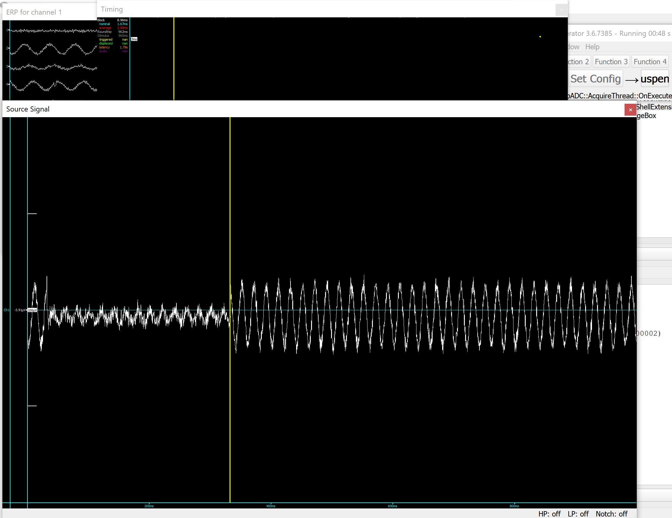
2110415-0

To convince myself. I really need to buy the best signal generator suggested here. But the RF attenuator is more doubtful whether you can accurately set it to 10uV. So without an RF attenuator. How would I get to 10uV using the best signal generators?

About the signal that is not really out of this world. Please consider the following common sense.

What do human brain, Lions brain and computers or AI have in common. They have basic units like neurons or processors or networks. These are very complex by themselves. But in humans, something in the highest aspect of the Universe somehow tap or hack into our nervous system. This gives us abstract level of thoughts, etc.  This can be illustrated by this Virginia quote:

"You may tear apart the baby's rattle and see what makes the noise inside, but there is a veil covering the unseen world which not the strongest man, nor even the united strength of all the strongest men that ever lived, could tear apart. Only faith, fancy, poetry, love, romance, can push aside that curtain and view and picture the supernal beauty and glory beyond. Is it all real? Ah, VIRGINIA, in all this world there is nothing else real and abiding.".

That was written a century ago. Now for the first time in human history. We may have the technology and science to push and open the veil covering the unseen world and reveal the super beauty ad glory beyond.

I'm verifying the experiments of some scientists who can measure the hacking signal to our nervous system. I mentione "hacking" just for my choice of word because it's really like hacking into the nervous system. If there is a voltage gradient on the skin caused by the field, or between inserted probes, you should be able to measure that.

What is it really we are trying to measure? It's composed of many frequencies like a rainbow or colors of field which anchor into the human nervous system and field. It's not one frequecy because the different colors have different frequencies.

2110433-1

Let's go back to baby. In a baby. The chakras or sensors were just being developed. It looks like this as seen by thousands of people worldwide (including hundreds I know. I am involved in one of the most extensive paranormal organization in the world).
2110421-2

Where do the chakras or field of energy come from. Somehow the higher aspect of the Universe anchors an aspect of its consciousness into humans to grow and extend the reach or influence. The power has been there since the Big Bang and set the constants of nature such that humans can evolve and grow to become vessels of the power and essence of the Universe.
2110427-3

As the baby grows into adult. The chakras are also developed. Remember they vessels of our higher aspect. The analogy is like a radio being human body and the electromagnetic transmission being the heart and soul of the radio. Right now what's happening is like 2 opposite camps fighting. One composed of group of people who hold the radio set tight and convinced all the signal originated inside. The other camp is convinced the electromagnetic wave is the radio and ignore the complexities of the radio set. This latter are many new age fanatics who were so ignorant of basic medical or science. So they keep on talking of auras only. The experiments to measure them will answer whether they have voltage gradients to be measurable. Whether it is measurable by biopotential sensors or not can be one of the keys to eventually finding the right equations akin to Maxwell equations or the Schrodinger Equations in the quantum.  I'm open to whether the gradients existed or not and not biased in any way.

2110439-4

2110445-5

2110451-6


The chakras just like the body can have disorders. In fact. In my life, I've been involved in fixing the disorders in the chakras. Without treating them. It can manifest in countless psychological ills and disorders that can be life long and lingering.

Do you understand? Anyway thanks for all the electronic tips. Now I'm focusing on Mathcad and signal analysis to replicate the experiments of those who found sigma 5 proof of the signal that range from 300Hz to 2400Hz. It is not one frequency because just like colors, it has multiple frequency like a rainbow, I'm not even sure if it is 10uV or 30uV or higher, although the lower limit seems to be 10uV. If there is nothing to all this. Then it is ok, because it can exclude a very important sector in experimental and theory space to arrive at the correct Theory.


Online radiolistener

  • Super Contributor
  • ***
  • Posts: 3386
  • Country: ua
Re: Most accurate signal generator
« Reply #161 on: April 10, 2024, 08:18:25 am »
As the baby grows into adult. The chakras are also developed. Remember they vessels of our higher aspect. The analogy is like a radio being human body and the electromagnetic transmission being the heart and soul of the radio. Right now what's happening is like 2 opposite camps fighting. One composed of group of people who hold the radio set tight and convinced all the signal originated inside. The other camp is convinced the electromagnetic wave is the radio and ignore the complexities of the radio set. This latter are many new age fanatics who were so ignorant of basic medical or science. So they keep on talking of auras only. The experiments to measure them will answer whether they have voltage gradients to be measurable. Whether it is measurable by biopotential sensors or not can be one of the keys to eventually finding the right equations akin to Maxwell equations or the Schrodinger Equations in the quantum.  I'm open to whether the gradients existed or not and not biased in any way.
Sorry, but the things which you're talking about looks like drugs addicted delirium or some kind of dangerous brainwashing sect...


It is not one frequency because just like colors, it has multiple frequency like a rainbow, I'm not even sure if it is 10uV or 30uV or higher, although the lower limit seems to be 10uV. If there is nothing to all this. Then it is ok, because it can exclude a very important sector in experimental and theory space to arrive at the correct Theory.

Regarding to the frequencies, there is not a problem to detect 10 uV single frequency or multiple frequencies, just capture some long enough sample and process it with FFT, you will see all frequencies which are presented in the signal and their power level which can be easy recalculated to voltage if you know the impedance.
« Last Edit: April 10, 2024, 08:22:17 am by radiolistener »
 
The following users thanked this post: egonotto

Offline Kean

  • Supporter
  • ****
  • Posts: 2099
  • Country: au
  • Embedded systems & IT consultant
    • Kean Electronics
Re: Most accurate signal generator
« Reply #162 on: April 10, 2024, 08:34:41 am »
I was pretty sure I had seen some of these images before.

https://www.eevblog.com/forum/dodgy-technology/tobiscope-design-(with-instructions-from-the-cia)/msg5085796/#msg5085796

So I suspect loop123 is the same as previously banned user bonyz who posted similar garbage.
 
The following users thanked this post: egonotto, newbrain, abeyer

Offline ebastler

  • Super Contributor
  • ***
  • Posts: 6510
  • Country: de
Re: Most accurate signal generator
« Reply #163 on: April 10, 2024, 08:45:55 am »
So I suspect loop123 is the same as previously banned user bonyz who posted similar garbage.

Good catch! Yes, it's very similar stuff; Dr. Tiller makes an appearance as well. Time for another ban, I guess...
 
The following users thanked this post: egonotto

Online Aldo22

  • Frequent Contributor
  • **
  • Posts: 695
  • Country: ch
Re: Most accurate signal generator
« Reply #164 on: April 10, 2024, 08:48:47 am »
@loop123: I think metaphysics works even better without electronics!  ;)
 

Offline Halcyon

  • Global Moderator
  • *****
  • Posts: 5681
  • Country: au
Re: Most accurate signal generator
« Reply #165 on: April 10, 2024, 08:55:34 am »
I was pretty sure I had seen some of these images before.

https://www.eevblog.com/forum/dodgy-technology/tobiscope-design-(with-instructions-from-the-cia)/msg5085796/#msg5085796

So I suspect loop123 is the same as previously banned user bonyz who posted similar garbage.

Yep and was also "planc" (also banned). Loves to use VPN's thinking that that'll cover his tracks. At least be a bit more creative with your fake email addresses mate ;-)
« Last Edit: April 10, 2024, 08:57:47 am by Halcyon »
 
The following users thanked this post: egonotto, Kean, ebastler, newbrain, alm, sarge

Offline vaualbus

  • Frequent Contributor
  • **
  • Posts: 370
  • Country: it
Re: Most accurate signal generator
« Reply #166 on: April 17, 2024, 08:51:25 am »
This must be the best "trolling" on engineer from a long time!
First it is clear you absolutely have no idea how basic electronic blocks works at all.
No idea on what noise is and how it "works" (or I rather said we should speak about the pdf/cfd of the noise anyway as we have not defined yet the bandwidth not the signal that is "measuring")
Also speaking of this good luck on having a 50000 amplifier and maintain low noise, not to spoiler you but the most noise in your system would be introduced by the first amplifier stage anyway, this is why on radio and wireless systems we have LNA (low noise amplifier).
 
Anyway, that was ok if your were a newbie of some kind, but then the last part of this thread is so funny.
As a suggestion I would use some quantum mechanics entanglement effects at room temperature (of course) to have your circuit working  :popcorn:

Anyway Iin my point of view you are having fun of us, but we are ready to fight back :box: :box: !
Anyway, was a good reading! ;)


Share me

Digg  Facebook  SlashDot  Delicious  Technorati  Twitter  Google  Yahoo
Smf