Author Topic: new killer scope in town - a true game changer from R&S - RTB2002 & RTB2004  (Read 817771 times)

0 Members and 2 Guests are viewing this topic.

Offline Joel_l

  • Frequent Contributor
  • **
  • Posts: 268
  • Country: us
I tend to not like glossy screens either. Like others have mentioned, I will add a screen protector if I find it too annoying.

Mine finally made it to my local post office this morning, hope to have it in my hands this afternoon.
 

Offline AndyP

  • Contributor
  • Posts: 41
  • Country: gb
Quite a few of the features on the RTB2000 are also on the RTM2000 'scope for those needing a higher spec offering. No touch screen though, but several other features similar, we bought a fully loaded mixed signal RTM2000 for marginally less than a KS MSO 3000.
 

Offline Joel_l

  • Frequent Contributor
  • **
  • Posts: 268
  • Country: us
My scope finally showed up today. Box was beat ( a pretty light weight box ) and the packaging is marginal. My scope came without any protective cover on the screen, scope was just in an anti static bag.

As my first go with it I connected it to my signal generator and I could not get a stable trigger looking at a 100MHz sine wave. After a few minutes of fusing with it, started to get things to look OK. I'll have to play a bit to make sure it's not me.

All the documentation I got is in German.

Is this how everyone else got their scopes?

Right now my first impressions are mixed.

Joel
« Last Edit: April 08, 2017, 10:03:41 pm by Joel_l »
 

Offline Joel_l

  • Frequent Contributor
  • **
  • Posts: 268
  • Country: us
OK, now I've had a chance to play a little more and I am happy with the scope.

I do notice I have a hard time acquiring very low level signals. When I set my signal generator say to -40dbm I cannot get a good trigger. If I go to say -20dbm, I get a trigger and then lower the level from there and stay triggered.

Is there a way to set a screen blanking time? I have not found it in the manual or menus yet.


Offline thanasisk

  • Regular Contributor
  • *
  • Posts: 101
  • Country: nl
Played around a bit with remote commands today on my box and found a neat way to find out the right command I wanted to share with you.

Historically if I needed a remote command I digged through the manual, which by the way seems to be still growing for the RTB2000? (at least every time I open it I have a new chapter  :o ??)

Instead for the RTB2000 I use this awesome USB connection and just copy the setting file (setup) directly after preset and take a second one after setting all settings. Doing a quick compare using KDIFF3 (or any other comparison app) and I have all the remote commands I need  8)

Never got this so easy. That's a big  :-+ R&S!

This is cool

Have you tested the peak search function on the fft/math channel?

According to the datasheet:

Search function
Functions search types edge, width, peak, rise/fall time, runt,
data2clock, pattern, protocol (available
with R&S®RTB-K3 option)
configuration manual level setting, adjustable hysteresis
display of search events in diagram (markers) and in result table
Sources R&S®RTB2002 channel 1, channel 2,
math waveform, D0 to D15
(with R&S®RTB-B1 option)
R&S®RTB2004 channel 1, channel 2, channel 3,
channel 4, math waveform, D0 to D15
(with R&S®RTB-B1 option)
 

Offline Joel_l

  • Frequent Contributor
  • **
  • Posts: 268
  • Country: us
Now I'm getting to know what the scope can and can't do. I pushed the scope quite a bit with low level high frequency sine wave from my signal generator. Granted I think the only reason it is working is the repetitive wave form but it does give me an idea of what it can do. Attached are two captures, one at 900MHz and one at 1GHz. The frequency counter seems to quit around 500MHz. Ignoring attenuation and other issues, not too bad.


Offline Octane

  • Regular Contributor
  • *
  • Posts: 103
  • Country: us
Serious question: why do you test at 300MHz scope at 900MHz and 1GHz?
W4MFT
 
The following users thanked this post: nugglix, fonograph

Offline Joel_l

  • Frequent Contributor
  • **
  • Posts: 268
  • Country: us
To learn its limitations as a useful tool. Most scopes will go beyond their spec'd frequency.  Pushing a sine wave is pretty easy and it was just easy for me to do. I need better probes before I can test real limitations. There are issues that will creep in but if you are aware of them you can usually work with it. It all depends what you want to do.
« Last Edit: April 09, 2017, 03:32:01 am by Joel_l »
 
The following users thanked this post: fonograph, Octane

Offline rf-loop

  • Super Contributor
  • ***
  • Posts: 4091
  • Country: fi
  • Born in Finland with DLL21 in hand
Serious question: why do you test at 300MHz scope at 900MHz and 1GHz?

It is also important to know analog front end bandwidth.

Sorry this image txt is finnish language but main thing is perhaps clear.
Note that many times oscilloscopes nameplate BW is over image fBW usually 1.3 - 1.8x when signal is directly connected to 50 ohm input with good impedance match. (combination BW, Probe + scope front is other case)
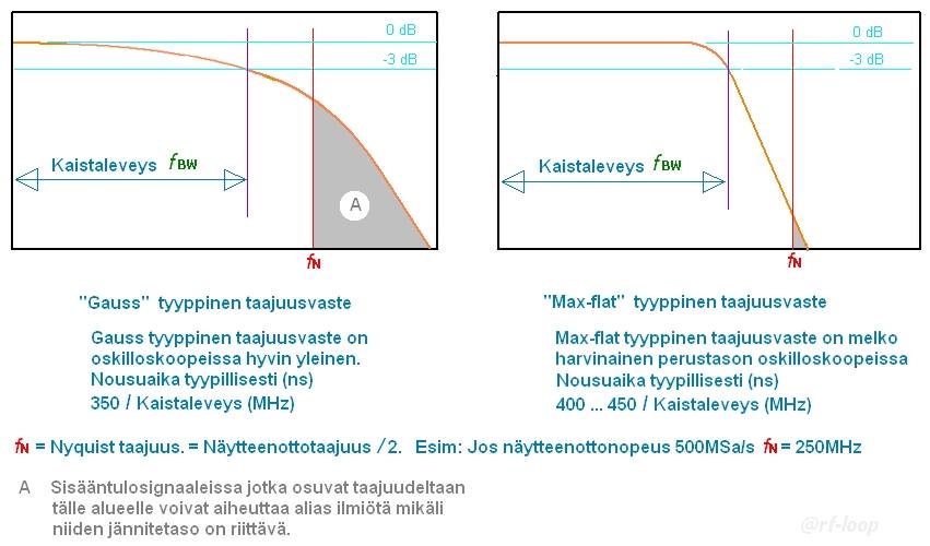


In image all what is in grey area (A) produce alias.
If want be sure that there is not high amount of aliasing then analog front end need filter out all frequency components what go over fNyquist
In these images can not see how much high frequencies are attenuated, only can see that it can trig and produce sinewave image. But also, in these  images signal do not go to fNyquist what is in this case 1.25GHz. If this scope use not interleaved mode then samplerate maax is 1.25GSa/s and then fNyquist is 625MHz.

Many cheap oscilloscopes have analog front end what go far over  fNyquist  so that signal level is still high when reach  fNyquist.  In these cases specially with signals what have high frequency components, example fast edges, measurements may be total false due to aliasing.

For serious use it is very good to know true analog front end frequency bandwidth and BW shape also up to least  fNyquist.  Many times these "hackers" do not understand this at all or other reason is that just only do not care. Only what they understand (or want) is how much MHz and thinking that more is better. I have never seen "hacker" or modifier who make his equipment better so that they reduce BW and make BW shape more steep so that  fNyquist is enough attenuated.


But most important is: Know your tools. This may need many kind of tests before serious use.

If I can hope I like to see this R&S high class scope real analog front end BW shape  from 0 to 1.2GHz.

« Last Edit: April 09, 2017, 07:31:29 am by rf-loop »
I drive a LEC (low el. consumption) BEV car. Smoke exhaust pipes - go to museum. In Finland quite all electric power is made using nuclear, wind, solar and water.

Wises must compel the mad barbarians to stop their crimes against humanity. Where have the wises gone?
 
The following users thanked this post: AndyP, fonograph, Octane

Online nctnico

  • Super Contributor
  • ***
  • Posts: 26891
  • Country: nl
    • NCT Developments
If you look towards the oscilloscope, probes and the object under test as a system then it quickly becomes clear that having excess margin for the anti-aliasing filter isn't necessary. Let's say your are looking at a 75MHz square wave from a digital circuit on a 200MHz 500Ms/s scope with a standard 1:10 high impedance probe. The 5th harmonic of that 75MHz square wave will be at 375MHz and have a level of -14dB referenced to the 75MHz fundamental. If I look at my scope the anti-aliasing filter attenuates by about 10dB at 375MHz. The output resistance of logic is typically 33 Ohm. The probe impedance at 375MHz and 10pf capacitance is is 42 Ohm so that is (off the cuff) another 3dB. All in all the 5th harmonic appears 27dB (10^(27/20) = 22 times) lower than the fundamental at the ADC's input. If the signal is displayed with 3 divisions (in the real world you will have multiple signals on screen) then the 375MHz harmonic (mirrored to 125MHz due to aliasing) will occupy around 0.125 division. That probably won't even show due to the noise.
« Last Edit: April 09, 2017, 09:12:30 am by nctnico »
There are small lies, big lies and then there is what is on the screen of your oscilloscope.
 

Offline MrW0lf

  • Frequent Contributor
  • **
  • Posts: 922
  • Country: ee
    • lab!fyi
Serious question: why do you test at 300MHz scope at 900MHz and 1GHz?

First thing you do when get something new (scope, car, wife) is test for limits. Then you can be sure it will be ok under normal usage... But must watch out, your limits may be also subject to tests... :P
 

Offline Joel_l

  • Frequent Contributor
  • **
  • Posts: 268
  • Country: us
To add a little more to the other good explanations,

Lets say I'm looking at a digital bus, it's more than can I see a 300MHz digital signal flying across. What defects can I expect to catch on those fast rising/falling edges, will I see that non monotonic glitch that is causing my logic to get stupid?

If things are repetitive, It is easier to build a waveform and eventually see it, things that are one shot are much harder to capture and are more scope HW limited.

As has been mentioned, there are many aspects that limit what you can do. Pushing the scope is how you learn those limits.
 

Offline Octane

  • Regular Contributor
  • *
  • Posts: 103
  • Country: us
Thanks for all your explanations. I understand Shannon-Nyquist of course, but it never came to my mind that I would need to look deeply into the scope behavior above the stated BW or even close to it's sample rate. I would have assumed that the front end is built in a way so that everything above nyquist is sufficiently suppressed. So that aliasing (at least at full sample rate) does not occur (I know that sampler rate changes with time base, Nr of channels and so forth...). At least on an A-brand scope.
W4MFT
 

Online nctnico

  • Super Contributor
  • ***
  • Posts: 26891
  • Country: nl
    • NCT Developments
Having a small margin for the anti-aliasing filter to work can also be found on A-brand scopes but you'll have to look at higher bandwidth models especially with multiple channels on.
There are small lies, big lies and then there is what is on the screen of your oscilloscope.
 

Offline Joel_l

  • Frequent Contributor
  • **
  • Posts: 268
  • Country: us
So, I still haven't found automatic screen blanking, does it exist?
 

Offline mikeselectricstuff

  • Super Contributor
  • ***
  • Posts: 13736
  • Country: gb
    • Mike's Electric Stuff
So, I still haven't found automatic screen blanking, does it exist?
If you mean a screensaver, I don't think there is one - I've certainly not seen it.
 But why would you want it ? LCDs don't burn in to any noticeable degree.
Youtube channel:Taking wierd stuff apart. Very apart.
Mike's Electric Stuff: High voltage, vintage electronics etc.
Day Job: Mostly LEDs
 

Offline Joel_l

  • Frequent Contributor
  • **
  • Posts: 268
  • Country: us
They actually do and it's not as difficult as you think. There's also the life of the backlight.

I've seen LCD panels damaged after a couple of years of constant static images.

Then personal preference, I just rather have it dim after a time I can set.

So, I still haven't found automatic screen blanking, does it exist?
If you mean a screensaver, I don't think there is one - I've certainly not seen it.
 But why would you want it ? LCDs don't burn in to any noticeable degree.
« Last Edit: April 09, 2017, 07:24:40 pm by Joel_l »
 

Offline ws2812b

  • Regular Contributor
  • *
  • Posts: 52
  • Country: at
@mike: didn't you show the screensaver here: https://twitter.com/mikelectricstuf/status/846419601529430019
Roflmaopimp
 

Offline snoopy

  • Frequent Contributor
  • **
  • Posts: 767
  • Country: au
    • Analog Precision
Another review of this scope on youtube ;)


Online voltsandjolts

  • Supporter
  • ****
  • Posts: 2299
  • Country: gb
Wow, that sure is a very clean bench.
 

Offline eb4eqa

  • Regular Contributor
  • *
  • Posts: 98
Being colorblind I have a hard time telling CH1 from CH2 in my Agilent DSO-X3012A, which are Green and Yellow (I can't tell you which is which...). It would be fantastic to have yellow and blue for example, but it can't be adjusted.

I have been unable to find a reference to this on the RTB2000 manual. Can someone confirm if the colors can actually be changed? That would be a great selling point for us colorblinds....

Thank you,
Roberto


Offline mikeselectricstuff

  • Super Contributor
  • ***
  • Posts: 13736
  • Country: gb
    • Mike's Electric Stuff
Being colorblind I have a hard time telling CH1 from CH2 in my Agilent DSO-X3012A, which are Green and Yellow (I can't tell you which is which...). It would be fantastic to have yellow and blue for example, but it can't be adjusted.

I have been unable to find a reference to this on the RTB2000 manual. Can someone confirm if the colors can actually be changed? That would be a great selling point for us colorblinds....

Thank you,
Roberto
They can't be changed, though there are a couple of "rainbow" colour modes, which you might be able to use on one trace to differentiate it.
Youtube channel:Taking wierd stuff apart. Very apart.
Mike's Electric Stuff: High voltage, vintage electronics etc.
Day Job: Mostly LEDs
 

Offline Pinkus

  • Frequent Contributor
  • **
  • Posts: 773
Being colorblind I have a hard time telling CH1 from CH2 in my Agilent DSO-X3012A, which are Green and Yellow (I can't tell you which is which...). It would be fantastic to have yellow and blue for example, but it can't be adjusted.

I have been unable to find a reference to this on the RTB2000 manual. Can someone confirm if the colors can actually be changed? That would be a great selling point for us colorblinds....

Thank you,
Roberto
Oh yeah. I have the same problem. And as EVERY 20th male is effected, I am wondering for years why nobody ever had the idea of allowing a user defined color for each channel (even a selection list with just 16 entries would be fine). A scope with such a feature would have indeed a BIG USP!!!
If you are interested in this desease see here: http://www.color-blindness.com/deuteranopia-red-green-color-blindness/
Test out yourself. Maybe you will find out that you are affected too (I found out not before I was 18 by doing such a test but was always wondering how difficult the decoding of color coded resistors were for me). Test here: http://enchroma.com/test/instructions/


Online nctnico

  • Super Contributor
  • ***
  • Posts: 26891
  • Country: nl
    • NCT Developments
Being colorblind I have a hard time telling CH1 from CH2 in my Agilent DSO-X3012A, which are Green and Yellow (I can't tell you which is which...). It would be fantastic to have yellow and blue for example, but it can't be adjusted.

I have been unable to find a reference to this on the RTB2000 manual. Can someone confirm if the colors can actually be changed? That would be a great selling point for us colorblinds....

Thank you,
Roberto
Oh yeah. I have the same problem. And as EVERY 20th male is effected, I am wondering for years why nobody ever had the idea of allowing a user defined color for each channel (even a selection list with just 16 entries would be fine). A scope with such a feature would have indeed a BIG USP!!!
Tektronix was ahead then with their TDS500/600/700 series. These allow to set/change all colors for the traces, user interface and hardcopy output.
There are small lies, big lies and then there is what is on the screen of your oscilloscope.
 

Offline PA0PBZ

  • Super Contributor
  • ***
  • Posts: 5125
  • Country: nl
Being colorblind I have a hard time telling CH1 from CH2 in my Agilent DSO-X3012A, which are Green and Yellow (I can't tell you which is which...). It would be fantastic to have yellow and blue for example, but it can't be adjusted.

Will you be able to pick 4 colors that you can easily tell apart from each other?
Keyboard error: Press F1 to continue.


Share me

Digg  Facebook  SlashDot  Delicious  Technorati  Twitter  Google  Yahoo
Smf