Regarding D1 and D4, at low frequencies the only difference between normal and Schottky diodes is the control voltage offset for the PIN diode attenuator/limiter. At 100MHz the difference is negligible in this application.
Much more important is that these diodes need to be fast enough to provide a proper detector function up to at least 2GHz. I’m not aware of any normal Si-diode that could do that, but an average Schottky diode won’t be any better either. You really need an ultrafast diode specifically designed for RF detector/mixer applications.
Just to illustrate the difference, I’ve simulated your input circuit with three different diodes for the RF detector: BAT15 (which is a proper RF mixer diode and roughly equivalent to BAT17, but appears to be more robust) BAT54 (which is not intended for HF) and 1N4148. See the results below:
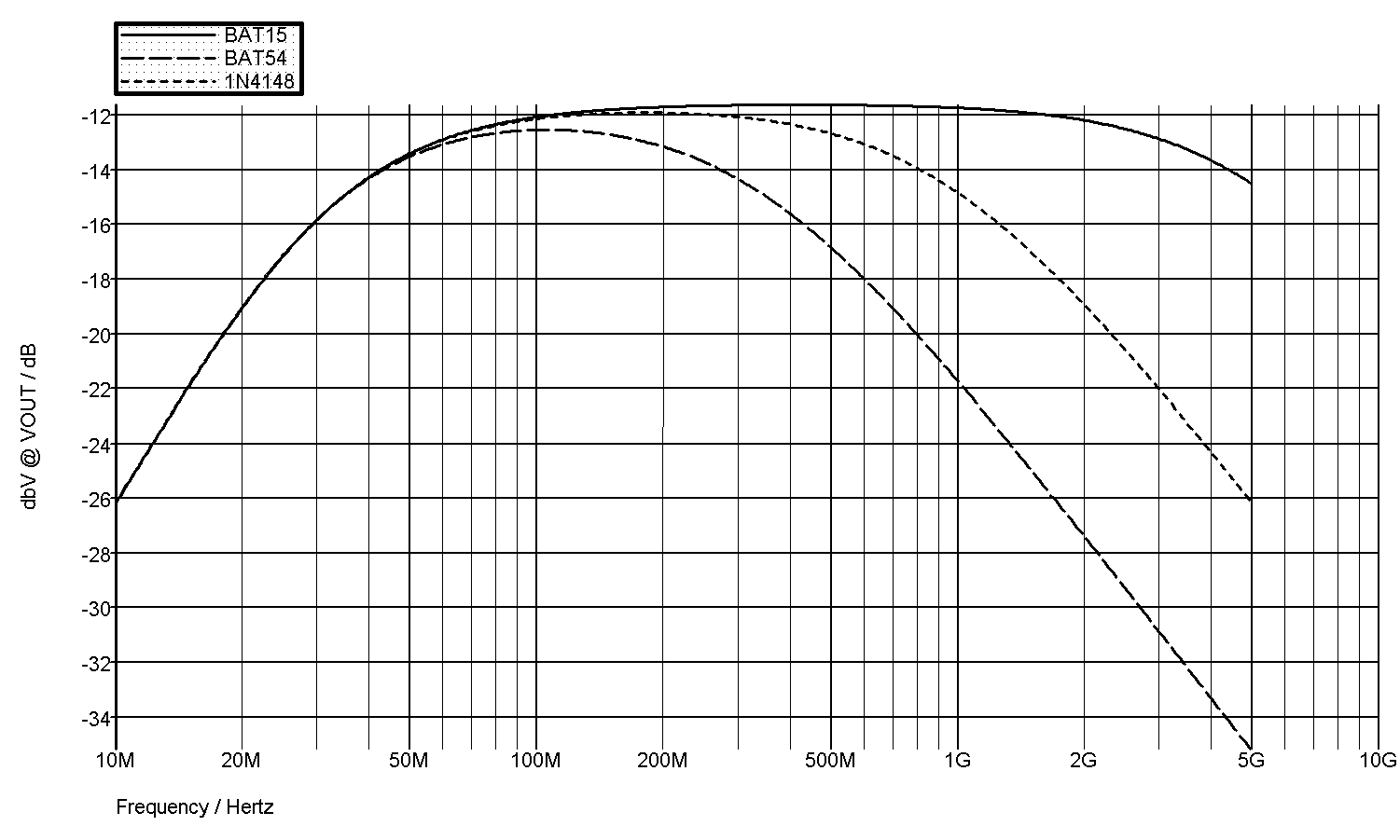
As can be seen, with BAT 15 the input circuit works up to 5GHz within less than 3dB, no problem. Of course, the parasitic elements in a real world circuit would make the results worse, but we are just looking at the diodes right now.
BAT54 on the other hand causes 10dB attenuation at 1GHz due to its large capacitance already, and the automatic level adjust for input attenuation/limiting will not work at that high frequencies either. Ironically, the latter will most probably not even be a problem, as it merely causes additional attenuation at higher input levels.
1N4148 does a significantly better job than the BAT54 and causes little more than 3dB attenuation at 1GHz.
One more remark with regard to the input circuit. R10, L2 and C12 can be omitted, as this quite obviously is nothing more than a low frequency gain correction for the discrete amplifier in the original Philips design, not needed for the MMIC. This will further improve the overall frequency response, because less components in the signal path also means less parasitics.
Regarding the notch filter with C18, I don’t quite get it.
What’s the benefit of the prescaler turning off at higher frequencies?
And if there’s a benefit, wouldn’t be a lowpass filter be more suitable?
Finally for the ground plane. So I understand you only have a 2-layer PCB and there is no solid ground plane, i.e. other traces running on the same layer, thus disrupting it. Well, in this case, it’s not a ground plane any more. For a high frequency design like this, a 4-layer PCB with true ground (and supply) plane(s) would be clearly indicated.


