Author Topic: Replacement for the PM9610 Prescaler for Philips PM6654 High precision Counter  (Read 28877 times)

0 Members and 1 Guest are viewing this topic.

Offline SaabFANTopic starter

  • Frequent Contributor
  • **
  • Posts: 735
  • Country: de
I actually thought about putting in some LL4148 but didn't do that because I though it was more important to use schottkys there.
Although at the moment it probably doesn't really make a difference because the highest frequency I can generate here is about 140MHz.

I have a solid ground plane underneath the second prescaler, but I have routed the +5V supply to the Standby-Pin on the top layer.

Interestingly, I have discovered that there seems to be a mechanical problem as well - If I put pressure on the board from the right side and at the correct spot, it suddenly puts out a perfectly clean ECL-Signal at 6,25MHz (Input = 100MHz). I have checked the signal at basically every place and it stays constant until the first prescaler. That one is the pressure-sensitive one...

I am now soldering another board with the copper-foil in place from the beginning and putting in 3,3nF coupling capacitors (easier to solder), as well as all the other hacks I have already employed to get it to work. Once I have it up and running I'll incorporate all the changes into the design  and order another batch in China.

It is true that my design could go higher than 1,5GHz because I use 2,5GHz prescaler-chips, but the counter is only able to count up to 120MHz, which translates to 1950MHz at the prescaler-input. Changing the capacitor will pull the notch higher in frequency - I just assumed 1nH inductance of the short 6mil trace parallel to the capacitor btw.

Online Performa01

  • Super Contributor
  • ***
  • Posts: 1625
  • Country: at
Regarding D1 and D4, at low frequencies the only difference between normal and Schottky diodes is the control voltage offset for the PIN diode attenuator/limiter. At 100MHz the difference is negligible in this application.

Much more important is that these diodes need to be fast enough to provide a proper detector function up to at least 2GHz. I’m not aware of any normal Si-diode that could do that, but an average Schottky diode won’t be any better either. You really need an ultrafast diode specifically designed for RF detector/mixer applications.

Just to illustrate the difference, I’ve simulated your input circuit with three different diodes for the RF detector: BAT15 (which is a proper RF mixer diode and roughly equivalent to BAT17, but appears to be more robust) BAT54 (which is not intended for HF) and 1N4148. See the results below:
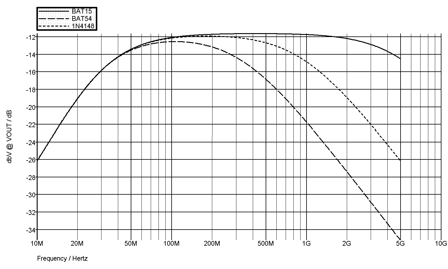


As can be seen, with BAT 15 the input circuit works up to 5GHz within less than 3dB, no problem. Of course, the parasitic elements in a real world circuit would make the results worse, but we are just looking at the diodes right now.

BAT54 on the other hand causes 10dB attenuation at 1GHz due to its large capacitance already, and the automatic level adjust for input attenuation/limiting will not work at that high frequencies either. Ironically, the latter will most probably not even be a problem, as it merely causes additional attenuation at higher input levels.

1N4148 does a significantly better job than the BAT54 and causes little more than 3dB attenuation at 1GHz.

One more remark with regard to the input circuit. R10, L2 and C12 can be omitted, as this quite obviously is nothing more than a low frequency gain correction for the discrete amplifier in the original Philips design, not needed for the MMIC. This will further improve the overall frequency response, because less components in the signal path also means less parasitics.

Regarding the notch filter with C18, I don’t quite get it.
What’s the benefit of the prescaler turning off at higher frequencies?
And if there’s a benefit, wouldn’t be a lowpass filter be more suitable?

Finally for the ground plane. So I understand you only have a 2-layer PCB and there is no solid ground plane, i.e. other traces running on the same layer, thus disrupting it. Well, in this case, it’s not a ground plane any more. For a high frequency design like this, a 4-layer PCB with true ground (and supply) plane(s) would be clearly indicated.
 
The following users thanked this post: chickenHeadKnob, edavid

Offline SaabFANTopic starter

  • Frequent Contributor
  • **
  • Posts: 735
  • Country: de
I don't know what the Philips-Engineers were thinking either when they put the notch-filter in there. Maybe it was smaller than using a low-pass on the crammed board... We'll probably never know because I doubt one of the designers of this board will come here and tell us :)

I have now ordered a few BAT17 from Conrad and a VCO to generate higher frequencies. But for the time the LL4148 will have to do. They are the ones with the lowest capacitance and specified reverse recovery time - some manufacturers specify it in the datasheet some unfortunately don't...

The ground planes on the top and bottom layer around the RF-Path is basically uninterrupted except for the supply of the MMIC and next to the Prescalers. The one mistake I probably made was that I routed the pullup for the first prescaler on the top layer underneath the chip instead of the bottom layer.
The updated PCB has the pullup-line for the standby-pin of both prescalers routed in a way that the RF-Path up to the second prescaler has an uninterrupted ground-plane beneath it.
A 4-Layer board seems like overkill to me and would also be prohibitively expensive (27€ vs. 84€ for 10 boards).

Online Performa01

  • Super Contributor
  • ***
  • Posts: 1625
  • Country: at
I don't know what the Philips-Engineers were thinking either when they put the notch-filter in there. Maybe it was smaller than using a low-pass The updated PCB has the pullup-line for the standby-pin of both prescalers routed in a way that the RF-Path up to the second prescaler has an uninterrupted ground-plane beneath it.

That sounds good.

Basically, you're right, the ground plane is most important for the high frequency section of the PCB.

But behind the 2nd prescaler, frequencies up to 120MHz aren't exactly low either. More importantly, this is the output of a digital divider, hence a digital signal with steep edges, hence lots of strong harmonics. So you should try hard to get a true (uninterrupted) ground plane for the entire signal path from input to output of the entire circuit - where "ground plane" refers to a reasonable low inductance (hence as wide as possible, but never less than say 3mm) copper trace going straight from input to output. This is the only thing that really matters. All the other ground connected copper areas will give some shielding, but do not contribute to signal integritiy in any way.
 

Offline SaabFANTopic starter

  • Frequent Contributor
  • **
  • Posts: 735
  • Country: de
I'm pretty sure it is working now. The little piece of copper foil underneath the first Prescaler seems to have been the solution. The counter is now able to count 100MHz sent to the prescaler. Above 100MHz the output of the Si5351 gets really jittery and the frequency count jumps up and down several MHz at the prescaler-input and even worse at the normal Input (terminated with 50 Ohms of course).
I haven't checked or adjusted the Standby-Circuit yet because I'm currently using a LL4148 as the detector-diode and BAS70 Schottky-Diodes (those were the ones with the lowest capacity I could find in my part-box - Unfortunately without any information about reverse recovery in the datasheet) for the automatic Attenuator.

Now I have to wait for the diodes and build something that can generate higher frequencies. I have 2 GHZ VCOs in my part-box, as well as an ADF4351 Module intended for my Spectrum Analyzer. I'm still at least a little bit tempted to buy the 8922H that is offered on ebay for about a year now for 350€ - It has an RF-Generator in it that goes up to 1GHz. :)

Well, if someone want's one of these prototype-boards, you can have them for 5€ per board plus shipping. They require cutting one trace and soldering a 1nF cap manhattan-style to the first pin of the first prescaler, as well as the copper-foil underneath the first prescaler (see Screenshot of the 3D-Rendering of the board).
I'm going to order the new design in 2 or 3 weeks I think. Still trying to get a HP Spectrum Analyzer and I need to save money^^

Offline SaabFANTopic starter

  • Frequent Contributor
  • **
  • Posts: 735
  • Country: de
Just to be clear: The 5€/PCB offer is for the unpopulated non-reworked PCB.

Offline SaabFANTopic starter

  • Frequent Contributor
  • **
  • Posts: 735
  • Country: de
I have just checked the lower end of the Prescaler-Board: It works down to at least 26MHz and about 5mVrms (measured by putting the output of a 26MHz TCXO through a 10dB and 14dB attenuator before feeding it into the counter).
I haven't gotten around to build a signal source that produces higher frequencies than 120MHz though, so I havent been able to check the performance at higher frequencies yet.

Offline david69

  • Regular Contributor
  • *
  • Posts: 93
Could I use Micrel prescaler SYS89875U for divider ?
There is reset as well, I enclose datasheet...
The PM9610 is divider 16?
 

Offline SaabFANTopic starter

  • Frequent Contributor
  • **
  • Posts: 735
  • Country: de
I don't think that that component is capable of producing the required signal-levels to drive the MC10102 NOR-Gate on the mainboard of the counter correctly.
It requires PECL-Levels and the chip you're asking about has LVDS-Outputs.
If you power it with close to +4V, it might work, but the chip is operating close to the maximum rating, which isn't recommended.

What you could do: Use a fast comparator at the output of the prescaler to produce the right signal levels for the ECL-Circuits on the mainboard.

But before that: Try to inject a 250 mVpp signal directly at the connector for the Prescaler-Module and measure the output of IC116 on the mainboard with channel C enabled. If there is a signal at pin 2 of IC116, your chip should work without a comparator.

With that in mind, every other 1:16 Prescaler should also work, provided that the output is PECL-Compatible.

Offline david69

  • Regular Contributor
  • *
  • Posts: 93
OK, Thank You much! The 1:16 dividers with LVPECL out
are reachable :) But there is connector BU2 and BU302
in elder version, but I don`t have it :( Where I can enable
input C on processor board?  David
 

Offline SaabFANTopic starter

  • Frequent Contributor
  • **
  • Posts: 735
  • Country: de
No idea what Connector BU302 / BU02 does.
My counter has no holes in the mainboard at that location and the service-manual doesn't mention anything that would connect to this connector and the diode located there.
It might be possible that the PM9610 was used in other counters as well, though, and those needed that connector to enable the high frequency channel.

To activate channel C on the PM6652 and PM6654, the pins 5 and 6 on connector BU107 have to be connected. That sets the configuration-bit for the RF-Option.


Btw. when testing the ADF4351 at different frequencies, I discovered that my board is able to prescale a 2.4GHz signal at 0dBm - But there's a notch around 1.6GHz (displayed frequency jumps all over the place) and 3GHz is too much (counter only displays "0."

Offline david69

  • Regular Contributor
  • *
  • Posts: 93
It would be like this scheme? I have several MiniCircuits
MAR6, or ERA3 should be working up 2GHz, the divider
MC12095 is easy to buy on Ebay :) This scheme would
be produced noice and wrong counter`s display, but I think in cause "right signal" the counter should be displayed right value :) Thanks and Happy Easter
 

Offline SaabFANTopic starter

  • Frequent Contributor
  • **
  • Posts: 735
  • Country: de
Yes, in the absence of a strong enough signal, the counter "counts" the noise. Also the Prescalers tend to self-oscillate at a certain frequency.
That's why the detector-circuit with the OpAmp is in there. It turns off the prescalers if the input-signal isn't strong enough, preventing any signal from appearing at the output.
I have included the detector-circuit on by board, but at the moment I've turned down the sensitivity of the circuit so the prescalers are always on. In essence it works like the circuit you drew up.
Important is a 30dB gain at the input to be able to count a 10mVrms signal and the limiter to go up to 12Vrms without blowing the amplifier.

Edit: You need a termination-resistor between the MMIC and the Prescaler. It doesn't have a 50 Ohm Input-Impedance, so no termination will create reflections and all kinds of trouble. The Terminator must be on its own segment of the signal-path with DC-Blocks in both directions. You cannot connect it directly to the input-pin of the prescaler. It would eat up the bias-voltage at that pin and make the ECL-Circuit inside Prescaler "deaf".
Also keep in mind to have a solid ground-plane underneath the chip, or it WILL become an oscillator (see earlier posts).

Offline david69

  • Regular Contributor
  • *
  • Posts: 93
My idea is use RF detektor LT5538 with comparator, where You
can set needed GAIN,
 

Offline SaabFANTopic starter

  • Frequent Contributor
  • **
  • Posts: 735
  • Country: de
Why use such an expensive chip when you can do the same with a simple diode? You don't want to measure the RF-Voltage accurately over a huge dB-Range. You just need a rough value for the comparator to turn the outputs on or off.

Offline david69

  • Regular Contributor
  • *
  • Posts: 93
You have true, LT is expensive, in package exacting for soldering
:(
I don`t know, but AD8313 in CONTROLLER MODE would be
controll directly divider MC12095? The scheme will be plainer
with this chip from Ebay?
 

Offline david69

  • Regular Contributor
  • *
  • Posts: 93
Attempt for improve scheme
« Last Edit: April 19, 2017, 05:44:15 pm by david69 »
 

Offline SaabFANTopic starter

  • Frequent Contributor
  • **
  • Posts: 735
  • Country: de
It generally should work, but I see a few problems:

- The MC12095 has it's input loaded with 56 Ohms. I made that mistake too and it just doesn't work. The sensitivity of the chip is extremely low if you put a resistor there. You need to place a DC-Block capacitor between the terminator and the input-pin of the Prescaler. It is an ECL-Circuit and has bias-voltage at the input-pin. Disturb that bias-voltage and the chip stops working correctly.
Also the DC-Block capacitors at the inverting inputs of the prescalers should match the capacitance of the other DC-Block caps.

- What's the purpose of R13? At 10 Ohms it will load down the output significantly. To have 5V across it, there needs to be a current of 500mA flowing through it. Way more than such a tiny chip can handle. If used at all, you can put 1k or 10k there. The SB-Input is relatively high impedance (as high as ECL-Inputs can be) and the AD8313 has a totem pole output-stage. If it want's the standby-pin to go LOW, it will pull it actively low, so no actual need for a pulldown-resistor.

- The detector and the Prescaler both have 50 Ohms termination, which results in a 25 Ohm load for the ERA-3 Amplifier, resulting in reduced amplitude. Made the same mistake and was pointed towards it by another forum-member. Replacing the termination-resistors with 100 Ohms resistors made the circuit work a lot better.

Also not so much a problem, but unecessary: You don't need a DC-Block capacitor at the output of the second Prescaler-chip. At that point you're connecting digital circuits, which generally speaking like their signals at either 0V or as close to Vcc as possible (in this case 5V).

Offline david69

  • Regular Contributor
  • *
  • Posts: 93
Yes, R13 is mistake, I was thinking about 1K resistor. I will revork
output from MAR6. Thank You.
 

Offline david69

  • Regular Contributor
  • *
  • Posts: 93
reworked scheme
 

Offline SaabFANTopic starter

  • Frequent Contributor
  • **
  • Posts: 735
  • Country: de
Your schematic looks good, except for the terminators R9 and R10.
The way you have connected them, you have formed a voltage-divider with R1, resulting in a much lower DC-Voltage at Pin 3 of the MMIC.
You need to isolate the DC-Supply from the terminators by two additional DC Block-Capacitors (see attached picture)

Offline david69

  • Regular Contributor
  • *
  • Posts: 93
I will make test platine :) Thank You
 

Online nctnico

  • Super Contributor
  • ***
  • Posts: 26868
  • Country: nl
    • NCT Developments
I'd put way more clearance between the HF traces and the ground pours. Say at least 2mm or so but there are online tools which can calculate the minimum clearance between a microstrip and ground pours.
There are small lies, big lies and then there is what is on the screen of your oscilloscope.
 

Offline david69

  • Regular Contributor
  • *
  • Posts: 93
reworked platine
« Last Edit: May 06, 2017, 11:07:49 am by david69 »
 

Offline SaabFANTopic starter

  • Frequent Contributor
  • **
  • Posts: 735
  • Country: de
I would also add Ground-Stitching Vias to the board to connect the top and bottom ground-plane.


Share me

Digg  Facebook  SlashDot  Delicious  Technorati  Twitter  Google  Yahoo
Smf