Author Topic: PRP1 - Low cost 2GHz power rail probe  (Read 30014 times)

0 Members and 3 Guests are viewing this topic.

Online Lexy

  • Contributor
  • Posts: 37
  • Country: nl
Re: PRP1 - Low cost 2GHz power rail probe
« Reply #150 on: April 03, 2026, 09:00:46 am »
Ow, I just noticed: The attenuation on the scope when I did the measurement is set to 1:1, not 1.3:1. So to get the noise at the input of the PRP1, the noise values should be multiplied with 1.3.
 
The following users thanked this post: Filippo52

Offline Filippo52

  • Regular Contributor
  • *
  • Posts: 197
  • Country: it
Re: PRP1 - Low cost 2GHz power rail probe
« Reply #151 on: April 03, 2026, 12:56:49 pm »
I informed Tszaboo yesterday that I may have solved the problem, but he's probably on vacation and hasn't responded. Since this is good news for the PRP1 probe, I'm letting everyone know.

The blame for everything lies primarily with me; I decided to measure the PRP1 probe's declared noise, and in doing so, I made two huge mistakes, driving good old Tszaboo crazy. He helped me so much. I also thank Martin72 for his help, who gave me some very useful advice in another discussion about noise measurements (but only of the MHO954 oscilloscope).

I'll try to summarize and hope I can be understood.

First, the essential things to know and follow, then my mistakes, and finally the final measurements with photos that demonstrate everything.

Noise measurements must be done with precise oscilloscope settings, and for the measurements to be comparable, they must be the same. There is no standard.
Let's start with the things common to all methods and state that we're talking about evaluating the noise of the PRP1 probe.

1 - the oscilloscope must be set to 50 ohms, and you don't need the supplied probes, but caps to close the inputs; this is mandatory on the PRP1 probe.
2 - setting 20 MHz filter. This is useful in general, but it's mandatory here because Tszaboo supplied the noise with such a filter.
3 - only one active channel. Of course, it's convenient to include a second one for immediate comparison, but since the full sampling rate, along with the scan speed, affects the measurement, it's best not to include anything else that affects these.

I'll show you more than one method; I'll start with the one suggested by Martin72, which is the one I used in the following photos.

a - Sensitivity at 1 mV/div
b - Scan speed at 1 ms/div
c - Memory set to use the maximum possible bandwidth, respecting point b above.

Then there's the mode Rigol uses for the MHO900, so it's not necessarily suitable for everyone.
a - 50 ohms, but it's already available as a general setting.
b - Sensitivity at 200 uV/div, and this automatically activates the 20 MHz filter for Rigol.
c - Scan speed at 20 uV/div
d - Memory depth at 1 Mpts
e - Sample rate at a maximum of 4 GSa/sec.

What we do in order:
1 - With the settings indicated, REPEAT I used Martin72's. We measure the oscilloscope noise without connecting anything to the channel input except a short-circuited plug.
2 - We plug in On the oscilloscope, the probe is also turned on and there is nothing at its input except a shorted cap.
3 - Using the well-known formula, calculate the probe's noise.
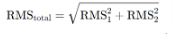
formula" border="0

Ecco le foto delle misure fatte con il metodo di Martin72
questa che segue è il rumore dell'oscilloscopio (inferiore a quello che dichiara Rigol, meglio così)

ultima-oscilloscopio-solo" border="0

questa altra è il rumore attaccando la sonda PRP! all'ingresso dell'oscilloscopio, sonda con il tappo corctocircuito sull'ingresso

ultima-oscilloscopio-con-sonda" border="0


Keep in mind that the calculation will not be precise because the oscilloscope we're using for the measurement has a noise level slightly lower than that of the probe being measured. In fact, be careful because if you have noisy oscilloscopes, the measurement will gradually become less precise.
I neglected the 1.3:1 correction factor because it makes little difference.
I repeat, to be very reliable, you need at least a factor of 10 between the measuring instrument and the one being measured.
With the values ​​I read, the PRP1 noise will be just over 70 uV. Tszaboo may be worried, but I repeat, measurements made this way aren't precise, and just over 70 uV is PERFECT.
With the errors I had made previously, the values ​​were 400 uV, even 800 uV when I read VRMS, and these worried me a bit.
I apologize and hope I've clarified things a bit, with the substantial help of Tszaboo and Martin72.

Now, to be honest, and I'd like someone who can clearly read the ripple of a simple cell phone charger: empty and fully charged... I'll wait for you.

Now let's talk about errors.

1 - What to measure? You need to measure AC-RMS and not VRMS, because VRMS also includes the DC offset and ruins the measurement.
2 - Using the cap on my Rigol MHO954 oscilloscope is optional because it makes no difference between with and without it. Anyway, test it and use the lowest value.
Instead, for the PRP1 probe it is ABSOLUTELY NECESSARY to have a cap that short-circuits the input otherwise the noise value will be 6-7 dB higher.
 

Online tszabooTopic starter

  • Super Contributor
  • ***
  • Posts: 9786
  • Country: nl
  • Current job: ATEX product design
Re: PRP1 - Low cost 2GHz power rail probe
« Reply #152 on: April 24, 2026, 05:10:11 pm »
The PRP1 is back in stock in Eleshop and the Zeenko store.
 

Offline bnz

  • Regular Contributor
  • *
  • Posts: 82
  • Country: de
Re: PRP1 - Low cost 2GHz power rail probe
« Reply #153 on: April 30, 2026, 08:11:11 am »
@tszaboo
Is there a chance to do a modification to rise the offset voltage slightly above 24V? Of cause on my own risk  :)
I would be interested to measure the bus supplying 24V regulators.
 

Online tszabooTopic starter

  • Super Contributor
  • ***
  • Posts: 9786
  • Country: nl
  • Current job: ATEX product design
Re: PRP1 - Low cost 2GHz power rail probe
« Reply #154 on: April 30, 2026, 08:44:58 am »
Hi bnz. The applicable offset voltage is a little higher than 24V, more like 25V. The specification is 24V, so it can do that 100% of the cases including tolerances. If you put a resistor in parallel with R37 (0603 component) (next to the potentiometer, in the middle) you can increase the voltage offset range. Something like 100K will give you about 28-29V.
The noise performance decreases with this of course. This is always a tradeoff.
If you decide to modify let me know how it goes.
Oh and the parts are rated to 50V max.
 

Offline crysti

  • Regular Contributor
  • *
  • Posts: 83
  • Country: ro
Re: PRP1 - Low cost 2GHz power rail probe
« Reply #155 on: May 11, 2026, 09:01:55 pm »
Thanks for the PRP1 project and the documentation around it. It seems like a very practical solution for measuring power rail ripple and noise.

I have a question/suggestion regarding a possible future PRP1 version.

Would it be technically feasible to make a variant with a much larger DC offset cancellation range, for example around ±120 V? One possible approach might be to run the internal offset circuitry from higher rails, such as ±12 V instead of ±2.5 V, while keeping a similar offset ratio. However, for practical reasons, the absolute resistor values would probably also need to be increased.

For example, instead of a low-value input/offset network, a higher-voltage version could use something like a 10:1 ratio with larger values, such as 500 kΩ / 50 kΩ or 1 MΩ / 100 kΩ, rather than 50 kΩ / 5 kΩ for DC. This would keep the offset scaling manageable while reducing the input current and resistor dissipation at high DC voltages. The high-voltage input resistor would likely need to be implemented as a series string for voltage rating, power dissipation, and reliability.

I understand that this would not be a trivial change, since it would affect capacitor voltage ratings, protection, creepage/clearance, noise, bias-current errors, output recovery, and general safety considerations. It would also not make the probe suitable for unsafe mains-referenced measurements unless the whole system and grounding are designed for that.

Another feature that could be interesting is automatic zero/offset adjustment. Instead of the manual coarse/fine potentiometers, the probe could use an MCU with an ADC monitoring the output DC level and a bipolar DAC generating the offset correction. Ideally, it could have an “Auto Zero / Hold” mode: press a button, the probe centers the output, then freezes the DAC value so that slow real rail variations are not continuously servoed away.

Has this kind of higher-offset / auto-zero version been considered, or would the added complexity, noise, and safety trade-offs make it impractical for this type of probe?
« Last Edit: May 12, 2026, 05:17:21 am by crysti »
 

Online tszabooTopic starter

  • Super Contributor
  • ***
  • Posts: 9786
  • Country: nl
  • Current job: ATEX product design
Re: PRP1 - Low cost 2GHz power rail probe
« Reply #156 on: May 11, 2026, 09:24:04 pm »
Hi crysti. There is always tradeoff of internal noise and offset capability. I see higher voltage requested by some people. What application would you use it ,where you need to measure ~microvolts of noise on a 120V rail? I could probably do it with a relay switching a range.

About the digital version, yes, some people suggested it, and it would make sense. I think it will be years before I come back to this project, right now I'm working on this for example:
https://www.eevblog.com/forum/testgear/hzb-7m-low-cost-high-impadance-buffer-by-tszaboo/msg6247697/#msg6247697
 

Online tszabooTopic starter

  • Super Contributor
  • ***
  • Posts: 9786
  • Country: nl
  • Current job: ATEX product design
Re: PRP1 - Low cost 2GHz power rail probe
« Reply #157 on: June 05, 2026, 09:20:19 am »
Here are some measurements that I was just doing on a board.
During EMC testing, we noticed some noise around 175MHz, that was still within the limits, but wanted to address it anyway. With near field probing we found a DC-DC converter that was making this noise on it's input. This was a 5V rail, so I measured it first with a regular probe, on an 8 bit scope, just to see that the radiated noise from the inductor, quantization noise probing etc, making this measurement impossible.

https://www.analog.com/en/resources/technical-articles/input-and-output-noise-in-buck-converters-explained.html
The noise appears when the FET is switching, as explained on Figure 9 of the paper above. For the analog devices test, the ringing seems to appear on the high side FET, for me it was the low side FET.
Here are the pictures of the switching noise on my board:


We've added an extra capacitor, 10nF, with the SRF at around 150MHz on the input. This reduced the amplitude of the noise by about 40%. Here are the after images:


We also tested the circuit before and after in a TEM cell (Which ntcnico suggested to get for such purposes, and I have to agree, very useful tool) and the radiated noise got reduced by 20dB, so now this is way below the limits required by the standards for compliance.
The  PRP1 made these tests possible to be performed in the time domain.
 

Offline hpw

  • Frequent Contributor
  • **
  • Posts: 507
  • Country: 00
Re: PRP1 - Low cost 2GHz power rail probe
« Reply #158 on: June 05, 2026, 05:47:25 pm »
for this purpose I used two 9V batteries... may some dislike..


Share me

Digg  Facebook  SlashDot  Delicious  Technorati  Twitter  Google  Yahoo
Smf