Author Topic: Show us your $20 Transistor Tester enclosures and mods (note: lots of pics)  (Read 45518 times)

0 Members and 1 Guest are viewing this topic.

Offline bitseekerTopic starter

  • Super Contributor
  • ***
  • Posts: 9057
  • Country: us
  • Lots of engineer-tweakable parts inside!
Starting this new thread for everyone to share how they package up their $20 transistor tester (LCR T3, LCR T4, GM320, AY-AT, etc.) or make other physical customizations to the basic kit.

For firmware-related discussion, visit the original thread $20 LCR ESR Transistor checker project.

Here are some examples to get started (click thumbnail for larger image):

upsss
Added an ISP connector, banana jacks, a Li-Ion battery which is charged through the DC connector, and replaced the crystal with a 16MHz one.


madires
My very first tester with the rotary encoder and frequency counter options.


pepe10000
A 3D-printed case with banana jacks.
« Last Edit: March 22, 2017, 04:29:08 am by bitseeker »
TEA is the way. | TEA Time channel
 
The following users thanked this post: bitwelder, PointyOintment, upsss, pepe10000

Offline upsss

  • Regular Contributor
  • *
  • Posts: 163
  • Country: us
Re: Show us your $20 Transistor Tester enclosures and mods
« Reply #1 on: March 09, 2017, 05:09:30 pm »
This was my original tester.
« Last Edit: March 09, 2017, 08:09:54 pm by upsss »
 
The following users thanked this post: bitseeker, pepe10000

Offline bitseekerTopic starter

  • Super Contributor
  • ***
  • Posts: 9057
  • Country: us
  • Lots of engineer-tweakable parts inside!
Re: Show us your $20 Transistor Tester enclosures and mods
« Reply #2 on: March 09, 2017, 06:30:29 pm »
Thanks, upsss. You can attach larger images. The forum will create the thumbnail for you. I had to do them manually in my original post because I referenced images from the original transistor tester thread rather than reupload.
TEA is the way. | TEA Time channel
 

Offline pepe10000

  • Regular Contributor
  • *
  • Posts: 87
  • Country: es
Re: Show us your $20 Transistor Tester enclosures and mods
« Reply #3 on: March 09, 2017, 08:29:39 pm »
This post seems to me a very good idea, so I'm going to put the photos of my 3 LCR-T4-H multimeters.

Box inclined printed in 3D:
https://www.thingiverse.com/thing:1372607
ISP Connector.
Ni-Mh 9v battery.
Charger module built with an LM317 with constant current.
Battery cutout switch.
Copper sticker for discharge of capacitors (used in glassworks).
Rubber stickers for the base (used as insulation in windows).
Stickers for serigraphs printed on inkjet printer and improved with spray varnish.
 
« Last Edit: December 18, 2017, 09:02:14 pm by pepe10000 »
 
The following users thanked this post: JoeO, upsss

Offline pepe10000

  • Regular Contributor
  • *
  • Posts: 87
  • Country: es
Re: Show us your $20 Transistor Tester enclosures and mods
« Reply #4 on: March 09, 2017, 08:37:19 pm »
Flat box printed in 3D:
https://www.thingiverse.com/thing:1797074
ISP Connector.
3.7V Lithium battery for a cell phone (recycled).
Charger module + power supply (9.2v).
LC filter (not necessary, but I like well filtered voltages).
Low battery LED.
Battery cutout switch.
Banana connectors.
Copper sticker for discharge of capacitors (used in glassworks).
Rubber stickers for the base (used as insulation in windows).
Stickers for serigraphs printed on inkjet printer and improved with spray varnish.
 
« Last Edit: December 18, 2017, 09:02:51 pm by pepe10000 »
 
The following users thanked this post: upsss

Offline pepe10000

  • Regular Contributor
  • *
  • Posts: 87
  • Country: es
Re: Show us your $20 Transistor Tester enclosures and mods
« Reply #5 on: March 09, 2017, 08:42:27 pm »
Door bell box:
https://www.ebay.es/itm/White-Plastic-Box-Project-Diy-Electronic-Case-Box-100-80-29mm-L-W-H/190998494412?hash=item2c7865bccc:g:K4IAAOxyUrZSptU7
ISP Connector.
Ni-Mh 9v battery.
Charger module built with an LM317 with constant current.
Battery cutout switch.
Adapters for SMD components.
Adapters for IR and Optocouplers.
Copper sticker for discharge of capacitors (used in glassworks).
Rubber stickers for the base (used as insulation in windows).
Stickers for serigraphs printed on inkjet printer and improved with spray varnish.

« Last Edit: March 20, 2018, 07:29:27 am by pepe10000 »
 

Offline casinada

  • Frequent Contributor
  • **
  • Posts: 599
  • Country: us
Re: Show us your $20 Transistor Tester enclosures and mods
« Reply #6 on: March 09, 2017, 08:52:22 pm »
Muy didacticos Pepe  :) :-+

Condensador tambien Capacitor  :)
 
The following users thanked this post: pepe10000

Offline upsss

  • Regular Contributor
  • *
  • Posts: 163
  • Country: us
Re: Show us your $20 Transistor Tester enclosures and mods
« Reply #7 on: March 09, 2017, 09:13:11 pm »
@pepe10000, What is this chart Cap vs. Voltage on the bottom of your testers?
 
The following users thanked this post: pepe10000

Offline aargee

  • Frequent Contributor
  • **
  • Posts: 873
  • Country: au
Re: Show us your $20 Transistor Tester enclosures and mods
« Reply #8 on: March 09, 2017, 09:19:24 pm »
Looks like a capacitor ESR values table. Recommended values for the capacitor vs the capacitor working voltage.

Nice cases, designed yourself?
Not easy, not hard, just need to be incentivised.
 
The following users thanked this post: pepe10000

Offline pepe10000

  • Regular Contributor
  • *
  • Posts: 87
  • Country: es
Re: Show us your $20 Transistor Tester enclosures and mods
« Reply #9 on: March 09, 2017, 09:24:37 pm »
@pepe10000, What is this chart Cap vs. Voltage on the bottom of your testers?

It is a table of ESR values of capacitors that I use as reference.
 

Offline linux-works

  • Super Contributor
  • ***
  • Posts: 1996
  • Country: us
    • netstuff
Re: Show us your $20 Transistor Tester enclosures and mods
« Reply #10 on: March 09, 2017, 09:25:26 pm »


just got that done today ;)

idea from the other main thread; I'll post more photos and the design files for those that want to lasercut their own.

 
The following users thanked this post: upsss, pepe10000

Offline pepe10000

  • Regular Contributor
  • *
  • Posts: 87
  • Country: es
Re: Show us your $20 Transistor Tester enclosures and mods
« Reply #11 on: March 09, 2017, 09:28:26 pm »
Looks like a capacitor ESR values table. Recommended values for the capacitor vs the capacitor working voltage.

Nice cases, designed yourself?

No, the 3D printed boxes are from a well-known website, which I have only modified to suit my taste

I do not know if the rules of the forum allow to put links to these 3D pages.

And the doorbell box is recycled and adapted.
« Last Edit: March 09, 2017, 09:30:02 pm by pepe10000 »
 

Offline upsss

  • Regular Contributor
  • *
  • Posts: 163
  • Country: us
Re: Show us your $20 Transistor Tester enclosures and mods
« Reply #12 on: March 09, 2017, 10:07:08 pm »
@pepe10000, What is this chart Cap vs. Voltage on the bottom of your testers?

It is a table of ESR values of capacitors that I use as reference.

FYI, there is no such thing as "standard" ESR values of Capacitance vs. Voltage.  "Regular" (crappy) Electrolytic of the same value and voltage can have up to TEN times higher ESR than a high quality "Low ESR" Electrolytic designed specifically for high frequency PWM circuits. 
« Last Edit: March 09, 2017, 11:03:48 pm by upsss »
 
The following users thanked this post: pepe10000

Offline aargee

  • Frequent Contributor
  • **
  • Posts: 873
  • Country: au
Re: Show us your $20 Transistor Tester enclosures and mods
« Reply #13 on: March 10, 2017, 12:06:47 am »
Yes, but it is a nice go-to reference for common DC / Low frequency expected values. Most of the ones I've changed are quite obviously stuffed, with the readings way above the ball park.
I usually go with an "A-B" comparison with a new good brand electrolytic if in doubt.

I'll post my Th!ngyverse sourced 3D printed case later. (That's not the website you're looking for - no?  8))
Not easy, not hard, just need to be incentivised.
 
The following users thanked this post: pepe10000

Offline pepe10000

  • Regular Contributor
  • *
  • Posts: 87
  • Country: es
Re: Show us your $20 Transistor Tester enclosures and mods
« Reply #14 on: March 10, 2017, 06:04:42 am »
I'll post my Th!ngyverse sourced 3D printed case later. (That's not the website you're looking for - no?  8))

Exactly, the designs I used are from that page.
 

Offline pepe10000

  • Regular Contributor
  • *
  • Posts: 87
  • Country: es
Re: Show us your $20 Transistor Tester enclosures and mods
« Reply #15 on: March 10, 2017, 06:21:51 am »
@pepe10000, What is this chart Cap vs. Voltage on the bottom of your testers?

It is a table of ESR values of capacitors that I use as reference.

FYI, there is no such thing as "standard" ESR values of Capacitance vs. Voltage.  "Regular" (crappy) Electrolytic of the same value and voltage can have up to TEN times higher ESR than a high quality "Low ESR" Electrolytic designed specifically for high frequency PWM circuits.

This table is quite old and as it says aargee only serves as a small reference of the expected values of ESR for low frequency.
 

Offline linux-works

  • Super Contributor
  • ***
  • Posts: 1996
  • Country: us
    • netstuff
Re: Show us your $20 Transistor Tester enclosures and mods
« Reply #16 on: March 13, 2017, 03:39:38 pm »
tweaked some measurements (allowing more room for finger/thumb to access the lever).  also added a small slide switch to cut power directly.


the pcb is red, so for fun, I went with red plastic, too.  I kind of like how it ended up.

I have extra cases; if you want one, PM me.  I also have extras of the mounting hardware (rubber feet, screws, standoffs, nuts, switch, small rotary encoder knob).  all the parts were from amazon, so for those that have amazon in their locale, these parts are somewhat easily buyable.

parts list:

kit: https://www.amazon.com/gp/product/B01HCXG9YS
rubber feet and 4-40 screws: https://www.amazon.com/gp/product/B007HKFPYM https://www.amazon.com/gp/product/B00137N2J0
small rotary knob: https://www.amazon.com/gp/product/B015E4CUAO
slide switch (bottom mount): https://www.amazon.com/gp/product/B007Q854MS
standoffs (4-40, 1/2" and 5/8"): https://www.amazon.com/gp/product/B00137S0V0 https://www.amazon.com/gp/product/B00137NJBQ
screws (4-40x1/4") https://www.amazon.com/gp/product/B00F34USTG/
plastic 4-40 nuts: https://www.amazon.com/gp/product/B009EENZ00
2-56 nuts and screws (for switch): https://www.amazon.com/gp/product/B00F3320HK https://www.amazon.com/gp/product/B009EENY88

other than the raw 1/8" plastic, I think that's all the parts that did not come in the kit, and that I used to build the unit, above (other than the 3 test lead mini banana jacks; those were from mouser or digikey and I don't have their #'s handy; but they are easy enough to find).

HTH
« Last Edit: March 13, 2017, 03:51:18 pm by linux-works »
 
The following users thanked this post: bitseeker, denimdragon

Offline bitseekerTopic starter

  • Super Contributor
  • ***
  • Posts: 9057
  • Country: us
  • Lots of engineer-tweakable parts inside!
Re: Show us your $20 Transistor Tester enclosures and mods
« Reply #17 on: March 13, 2017, 07:12:18 pm »
The red turned out great! One tweak that I might try on it would be to add a riser of some sort (IC socket(s)?) to raise the zif connector for easier access to the lever and the component under test.

Do you plan to add connectors for the signal gen and counter? I suppose at least one would fit on the side opposite the power switch.
TEA is the way. | TEA Time channel
 

Offline PointyOintment

  • Frequent Contributor
  • **
  • Posts: 327
  • Country: ca
  • ↑ I scanned my face
Re: Show us your $20 Transistor Tester enclosures and mods
« Reply #18 on: March 14, 2017, 01:12:24 am »
That looks amazing! One question: what does the 1112333 mean? Is it this layout?
1
1
1
2
3
3
3
NCNCNC2NCNCNC
I haven't seen any layout like that on the testers I've looked at closely so far.

When mine arrives (hopefully soon—I've waited 4 months so far) I think I'm going to do a 3D-printed case for it. I want exposed ZIF socket, exposed SMD pads, low-profile knob, and permanently attached leads at the top, with ideally both pointy probes and some kind of grabbers (double-ended). Does anybody know of leads like that, that come in three colors?
I refuse to use AD's LTspice or any other "free" software whose license agreement prohibits benchmarking it (which implies it's really bad) or publicly disclosing the existence of the agreement. Fortunately, I haven't agreed to that one, and those terms are public already.
 

Offline StillTrying

  • Super Contributor
  • ***
  • Posts: 2850
  • Country: se
  • Country: Broken Britain
Re: Show us your $20 Transistor Tester enclosures and mods
« Reply #19 on: March 14, 2017, 01:35:51 am »
Both rows of the zif are probably the same, I've got a yellow T4 one with a normal green backlight LCD, on that the zif connections are
1231111
1231111

That 1112333 zif arrangement looks more convenient than mine!
« Last Edit: March 14, 2017, 01:44:21 am by StillTrying »
.  That took much longer than I thought it would.
 

Offline madires

  • Super Contributor
  • ***
  • Posts: 7754
  • Country: de
  • A qualified hobbyist ;)
Re: Show us your $20 Transistor Tester enclosures and mods
« Reply #20 on: March 14, 2017, 01:51:44 am »
I like to following pinout (+/- is the optional Zener check up to 50V):
123+++--
112233+-

Another handy pinout would be:
12312321
11223321
 

Offline linux-works

  • Super Contributor
  • ***
  • Posts: 1996
  • Country: us
    • netstuff
Re: Show us your $20 Transistor Tester enclosures and mods
« Reply #21 on: March 14, 2017, 03:06:14 am »
the way this kit was made, the pin1 slots are the left 3, pin2 only has the middle slot and the rest of the 3 to the right are pin3.   seems very logical that way.  other layouts seem odd to me, but I had no choice with this kit ;)

on my chassis, I did not plan to add freq-out and voltage/freq-in, but I could be talked into it, I guess.  there is room on the back for connectors, but the front is taken by the battery.

as for the riser of the zif socket, I agree its down too low.  maybe a wire-wrap socket would be a good idea for the base, then press and glue the zif into the wirewrap socket.  not sure it will fit, as the wirewrap socket is machine pin style (round) and the pins on the zif are flat.

I also want to find a real zif socket since the fake 'textool' one will go 'funky' in no time flat.  its already acting funny (press the lever down and its sometimes hard to grab and push back up again).


that aside, I got some requests for this case from folks in europe.  I wonder: would someone be willing to be a middleman for me and take the combined pkg of plastic and re-mail out to the local guys who want one?  might be easier for me that way than sending X pkgs to various locations in europe.

I do plan to post the mechanical drawing (files) for this so anyone who has a laser cutter can do it or farm it out.  the only slight problem is that the thickness of the acrylic is somewhat non-standard; its less than 1/8" and if you use standard 1/8" plastic, the notch holes will be too tight.  I used what my local techshop had in stock, but unfortunately, they don't seem very keen on reordering and so I have no stock left right now and unless they order more (been waiting weeks for them to get on the ball!) I can't print anymore.  I keep asking them to order more plastic but they don't seem to care, for some reason (anyone know who the manager is of the redwood city tech shop?  no name or number is listed on the main site and I'd like to call that manager and let him know his people are not doing their jobs - no one is ordering more plastic and the desk jockeys don't ever relay my messages to the ordering person, sigh...).


Offline perieanuo

  • Frequent Contributor
  • **
  • Posts: 838
  • Country: fr
Re: Show us your $20 Transistor Tester enclosures and mods
« Reply #22 on: March 14, 2017, 06:54:38 am »
Lokk what this guy did, I think it's the best case I ever seen for the GM328.Maybe it may costs a little more,for me in France you go for 40 euros or more to print it but finally it's a semi-pro case.
Maybe even pro, the project was forced to obey the actual shitty solutions for i/o-s.
All credits go to the person who did this of course.
http://3dtoday.ru/3d-models/mechanical-parts/body/box_tft_gm328_transistor_tester_/


best regards to everyone,ovidiu
« Last Edit: March 14, 2017, 07:16:40 am by perieanuo »
 

Offline luma

  • Regular Contributor
  • *
  • Posts: 130
  • Country: us
Re: Show us your $20 Transistor Tester enclosures and mods
« Reply #23 on: March 14, 2017, 01:37:59 pm »
I printed this case from Thingiverse for my M12864 style tester:
 

Offline bitseekerTopic starter

  • Super Contributor
  • ***
  • Posts: 9057
  • Country: us
  • Lots of engineer-tweakable parts inside!
Re: Show us your $20 Transistor Tester enclosures and mods
« Reply #24 on: March 14, 2017, 08:49:14 pm »
That looks amazing! One question: what does the 1112333 mean?

I think the dropped '2' is for visual effect. It helps it not to blend in with the multiple '1' and '3'. I like it.
TEA is the way. | TEA Time channel
 
The following users thanked this post: PointyOintment

Offline Dubbie

  • Supporter
  • ****
  • Posts: 1115
  • Country: nz
Re: Show us your $20 Transistor Tester enclosures and mods
« Reply #25 on: March 15, 2017, 12:26:44 am »
Does no-one else use the SMD pads? I use them probably just as much as the ZIF socket.
 

Offline linux-works

  • Super Contributor
  • ***
  • Posts: 1996
  • Country: us
    • netstuff
Re: Show us your $20 Transistor Tester enclosures and mods
« Reply #26 on: March 15, 2017, 01:04:19 am »
That looks amazing! One question: what does the 1112333 mean?

I think the dropped '2' is for visual effect. It helps it not to blend in with the multiple '1' and '3'. I like it.

(smile) - yes, you got it.  I dropped the 2 below the 'line' just to set it off visually.  that's all it was about ;)
 
The following users thanked this post: PointyOintment

Offline ebastler

  • Super Contributor
  • ***
  • Posts: 6422
  • Country: de
Re: Show us your $20 Transistor Tester enclosures and mods
« Reply #27 on: March 15, 2017, 06:16:22 am »
Lokk what this guy did, I think it's the best case I ever seen for the GM328.Maybe it may costs a little more,for me in France you go for 40 euros or more to print it but finally it's a semi-pro case.
Maybe even pro, the project was forced to obey the actual shitty solutions for i/o-s.
All credits go to the person who did this of course.
http://3dtoday.ru/3d-models/mechanical-parts/body/box_tft_gm328_transistor_tester_/


best regards to everyone,ovidiu

Once you close the ZIF socket by pushing the lever down, how are you ever going to pry it back up again?
Not convinced...
 

Offline aargee

  • Frequent Contributor
  • **
  • Posts: 873
  • Country: au
Re: Show us your $20 Transistor Tester enclosures and mods
« Reply #28 on: March 15, 2017, 07:31:50 am »
If it's like mine, you just push the lever far enough to 'grab' the component and then push test while you're holding it.
Not easy, not hard, just need to be incentivised.
 

Offline Codebird

  • Regular Contributor
  • *
  • Posts: 161
  • Country: gb
Re: Show us your $20 Transistor Tester enclosures and mods
« Reply #29 on: March 15, 2017, 11:27:35 am »
Do diode testers count?

https://birds-are-nice.me/ipfs/Qmd8GXUEkw63J8SBmkS5thnoDTyJTyp1yM6SfzEHvLZp3M/tester_complete.jpg

0-5V (true zero) high-precision lower supply with voltage and current display, and serial output for drawing nice I/V graphs. Includes a built-in meter for voltage and current measurement using an external supply too. I built it to test schottky diodes. Can't trust eBay parts to be on spec - I got caught once by a diode sold as a schottky that turned out to be a regular diode with a false label on it.
 

Offline PointyOintment

  • Frequent Contributor
  • **
  • Posts: 327
  • Country: ca
  • ↑ I scanned my face
Re: Show us your $20 Transistor Tester enclosures and mods
« Reply #30 on: March 16, 2017, 10:14:23 am »
I do plan to post the mechanical drawing (files) for this so anyone who has a laser cutter can do it or farm it out.  the only slight problem is that the thickness of the acrylic is somewhat non-standard; its less than 1/8" and if you use standard 1/8" plastic, the notch holes will be too tight.

3 mm? Around here, that, not 1/8", is the standard.
I refuse to use AD's LTspice or any other "free" software whose license agreement prohibits benchmarking it (which implies it's really bad) or publicly disclosing the existence of the agreement. Fortunately, I haven't agreed to that one, and those terms are public already.
 

Offline linux-works

  • Super Contributor
  • ***
  • Posts: 1996
  • Country: us
    • netstuff
Re: Show us your $20 Transistor Tester enclosures and mods
« Reply #31 on: March 16, 2017, 05:48:35 pm »
2.64mm is what my mitutoyo calipers say.


Offline upsss

  • Regular Contributor
  • *
  • Posts: 163
  • Country: us
Re: Show us your $20 Transistor Tester enclosures and mods
« Reply #32 on: March 18, 2017, 07:10:59 am »
Lokk what this guy did, I think it's the best case I ever seen for the GM328.Maybe it may costs a little more,for me in France you go for 40 euros or more to print it but finally it's a semi-pro case.
Maybe even pro, the project was forced to obey the actual shitty solutions for i/o-s.
All credits go to the person who did this of course.
http://3dtoday.ru/3d-models/mechanical-parts/body/box_tft_gm328_transistor_tester_/


best regards to everyone,ovidiu

Once you close the ZIF socket by pushing the lever down, how are you ever going to pry it back up again?
Not convinced...

I solved the problem by simply bending up the lever.
 

Offline ebastler

  • Super Contributor
  • ***
  • Posts: 6422
  • Country: de
Re: Show us your $20 Transistor Tester enclosures and mods
« Reply #33 on: March 18, 2017, 10:48:41 am »
Does this count? Note the highly optimized human factors design, with easy access to the ZIF lever, SMD pad, and battery compartment... ;)

With hindsight, I should have put the battery holder on the left side, to make the SMD pads even more accessible. I had not wanted to block the LCD contrast pot, which sits on the left below the display, but I never touch that anyway.

I did patch in the encoder, on a PCB that was laid out for just a pushbutton. The layout was accommodating enough; drilling four extra holes and soldering two patch wires did the trick.
 

Offline bitseekerTopic starter

  • Super Contributor
  • ***
  • Posts: 9057
  • Country: us
  • Lots of engineer-tweakable parts inside!
Re: Show us your $20 Transistor Tester enclosures and mods
« Reply #34 on: March 20, 2017, 01:26:00 am »
Hehe, nice tweaks.
TEA is the way. | TEA Time channel
 

Online xrunner

  • Super Contributor
  • ***
  • Posts: 7513
  • Country: us
  • hp>Agilent>Keysight>???
Re: Show us your $20 Transistor Tester enclosures and mods
« Reply #35 on: March 20, 2017, 01:28:38 am »
Bookmark -

pic tomorrow ...
I told my friends I could teach them to be funny, but they all just laughed at me.
 
The following users thanked this post: bitseeker

Offline aargee

  • Frequent Contributor
  • **
  • Posts: 873
  • Country: au
Re: Show us your $20 Transistor Tester enclosures and mods
« Reply #36 on: March 21, 2017, 01:53:19 am »
Chalk and cheese.

Got the colour just right, it was printed before the Agilent arrived.
Not easy, not hard, just need to be incentivised.
 

Offline Dubbie

  • Supporter
  • ****
  • Posts: 1115
  • Country: nz
Re: Show us your $20 Transistor Tester enclosures and mods
« Reply #37 on: March 21, 2017, 03:02:26 am »
Ebastler, yours is the only one I would find useful so far! All the others don't have the SMD pads exposed.
 

Offline bitseekerTopic starter

  • Super Contributor
  • ***
  • Posts: 9057
  • Country: us
  • Lots of engineer-tweakable parts inside!
Re: Show us your $20 Transistor Tester enclosures and mods
« Reply #38 on: March 21, 2017, 04:35:24 am »
@aargee: That's quite a color match. Just a coincidence or did you have another Agilent/Keysight meter to base your filament color on?
TEA is the way. | TEA Time channel
 

Offline ebastler

  • Super Contributor
  • ***
  • Posts: 6422
  • Country: de
Re: Show us your $20 Transistor Tester enclosures and mods
« Reply #39 on: March 21, 2017, 10:50:48 am »
Ebastler, yours is the only one I would find useful so far! All the others don't have the SMD pads exposed.

Thanks! Laziness might have played a part in my "design decision" as well, to be honest...  ;)

Pepe10000's black enclosure (on the first page of this thread) also does a nice job keeping everything accessible. The board he used seems well-suited for an enclosure, with all user interface elements sitting nicely on the same level.
« Last Edit: March 21, 2017, 10:56:39 am by ebastler »
 

Online xrunner

  • Super Contributor
  • ***
  • Posts: 7513
  • Country: us
  • hp>Agilent>Keysight>???
Re: Show us your $20 Transistor Tester enclosures and mods
« Reply #40 on: March 21, 2017, 11:29:42 am »
Here's what I threw together.
I told my friends I could teach them to be funny, but they all just laughed at me.
 
The following users thanked this post: PointyOintment

Offline aargee

  • Frequent Contributor
  • **
  • Posts: 873
  • Country: au
Re: Show us your $20 Transistor Tester enclosures and mods
« Reply #41 on: March 21, 2017, 01:11:17 pm »
@aargee: That's quite a color match. Just a coincidence or did you have another Agilent/Keysight meter to base your filament color on?

Purely coincidence, the roll of PLA 3D filament I have here is an exact match for Agilent orange!
Not easy, not hard, just need to be incentivised.
 

Offline bitseekerTopic starter

  • Super Contributor
  • ***
  • Posts: 9057
  • Country: us
  • Lots of engineer-tweakable parts inside!
Re: Show us your $20 Transistor Tester enclosures and mods
« Reply #42 on: March 21, 2017, 11:50:37 pm »
Amazing coincidence!
TEA is the way. | TEA Time channel
 

Offline linux-works

  • Super Contributor
  • ***
  • Posts: 1996
  • Country: us
    • netstuff
Re: Show us your $20 Transistor Tester enclosures and mods
« Reply #43 on: March 22, 2017, 02:51:04 am »
I guess the lack of smd pad access does not bother me.  if I need to check an smd device, I might just make a jig that plugs into the zif socket and gives me 'direct' access that way.

this could be a good small project; design a small board that has .1" spacing for pins and various smd layouts on the top board that connect to the 1/2/3 pins.  there could be a panel of such boards with different spacing and you just plug in the right extender module.

the laser-cut method does not lend itself well to multi layers.


Offline bitseekerTopic starter

  • Super Contributor
  • ***
  • Posts: 9057
  • Country: us
  • Lots of engineer-tweakable parts inside!
Re: Show us your $20 Transistor Tester enclosures and mods
« Reply #45 on: March 22, 2017, 04:27:43 am »
Over the past couple years, I've seen in the original thread several variations of test pads for these testers, either integrated into the case or via adapter PCB. After scrolling through over 2100 posts :o trying to find them, here's a summary:

This one has the ZIF socket and SMD pads on the adapter and connects via banana plugs:


Someone else made adapters like these:


Mauro made his own:


One by zhqsoft:


This one has many layouts:


And a Russian tester with DIP socket and adapter:
TEA is the way. | TEA Time channel
 
The following users thanked this post: mauroh, perieanuo

Offline bitseekerTopic starter

  • Super Contributor
  • ***
  • Posts: 9057
  • Country: us
  • Lots of engineer-tweakable parts inside!
And now, for something completely different. An LCR-T3 in an audio cassette case.

TEA is the way. | TEA Time channel
 
The following users thanked this post: GerritMax

Offline linux-works

  • Super Contributor
  • ***
  • Posts: 1996
  • Country: us
    • netstuff
has anyone done a Qi charged build before? ;)


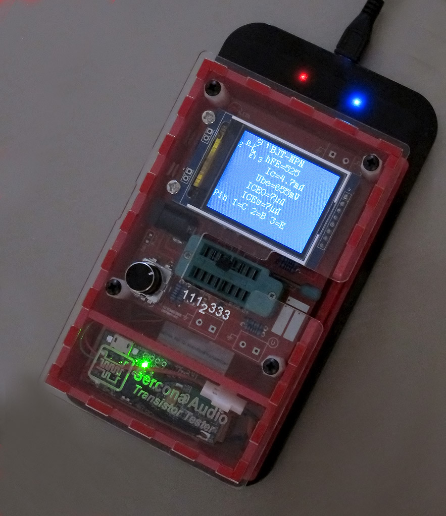
this is using off-the-shelf parts, more or less.  a $10 credit card thing that is a qi coil and circuit in a thin card; this is taped to the base of the plastic box, inside the box (the thickness of the plastic is between the sender coil and this unit's coil).  a $10 charger/boost converter board from amazon (many models like it at the usual places).  this takes 5v from a usb connection (or my qi coil!) and charges a 3.7v lipo battery.  I used a quadcopter toy battery that is 500mah rated and should run this tester for a fairly long time (have not tested it yet for run-time). 

that's really all this is, the $10 qi coil card thing, remove its usb male and solder to its 2 wires after confirming which is red and which is black (they are flat wire and the plastic has to be scraped off from one end and then wires soldered to that copper flex trace.  its not hard to do).  and then some combo of a charger board and a boost converter to create the final 5v.

I used my existing box design that worked for a 9v battery but the wiring now goes to the input of the volt reg chip instead of thru a diode or transistor.  I get a 'warning' at power-up (I'll get rid of that with a custom sw build) but other than that, it seems to run ok on 5v.


also on this build: I removed the crappy TFXTDOL zif and put in a real, actual, honest TEXTOOL socket.  found a few of them, used, at my local surplus store.  note, this one was 16pin so I had to cut off the top 2 pins since the pcb did not have spare holes (that would have been nearly brilliant of the pcb designer to allow for 14 and also the slightly more common (imo) 16pin zif sockets.  there's still room on the board for even longer sockets.  the china fakes are 'genuine crap' ;)  I was going to buy new textool sockets ($16 or more, sigh) but found some used ones that were still in good shape.


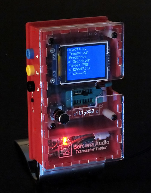
edit: 2nd photo with the tester on a charging stand.  usb charging cord for stand is too dark to be seen in this photo.  stand has adjustment knob on the back to let you slide the coil up and down.  loosen, move coil until you get max output with the device, then tighten and its now aligned to that device, perfectly.  here, the red light shows its charging.
« Last Edit: March 25, 2017, 11:45:32 pm by linux-works »
 

Offline bitseekerTopic starter

  • Super Contributor
  • ***
  • Posts: 9057
  • Country: us
  • Lots of engineer-tweakable parts inside!
That's the first Qi-compatible rechargeable version I'm aware of. Nicely done! :-+
TEA is the way. | TEA Time channel
 

Offline perieanuo

  • Frequent Contributor
  • **
  • Posts: 838
  • Country: fr
Here's my egg :)
i know it's not even finished (still looking for a cheap glass or plexi to cover the display from inside box)
cheap stuff like 5 euros for the box
the back side has also a DB9 connector for firmware update,opposite gender regarding to testing DB9 conn so anybody can't reverse those two
reason:that is what I had in my secret closet :)
 

Offline madires

  • Super Contributor
  • ***
  • Posts: 7754
  • Country: de
  • A qualified hobbyist ;)
The 644/1284 dev board with an ILI9341/9342 display board. The input protection (SRV05-04 and TVS) and the relay for the SamplingADC's cap are missing.
« Last Edit: May 05, 2017, 11:20:29 am by madires »
 
The following users thanked this post: cdev, bitseeker, elecdonia, jakeisprobably, pepe10000, UKTech

Offline linux-works

  • Super Contributor
  • ***
  • Posts: 1996
  • Country: us
    • netstuff
I just bought a 3d printer.  would like to see how the 3d printed cases work out.  the one that was posted on the .ru site, can anyone send me a link to the stl or gcode files?

I'm referring to the m328 color version, knob on the left, zif on the right.

Offline bitseekerTopic starter

  • Super Contributor
  • ***
  • Posts: 9057
  • Country: us
  • Lots of engineer-tweakable parts inside!
This one? https://yadi.sk/d/yW8xa5NJgUo5z/M328Kit%2BTFT

If not, navigate up one level and there are other versions.
TEA is the way. | TEA Time channel
 

Offline pepe10000

  • Regular Contributor
  • *
  • Posts: 87
  • Country: es
Hello, if it is the bitseeker comment, GM328B (AY-AT DIY Kit) there is not much variety to choose.

For my taste the best are these two, I attach the files in case you need them and photos of the assembly that I am performing (they are not finished).

They have some design flaws but they can be used.

A greeting.

P.S. Unzip with WinRar.
 
The following users thanked this post: bitseeker, nicolasCR

Offline linux-works

  • Super Contributor
  • ***
  • Posts: 1996
  • Country: us
    • netstuff
thanks for the links.  I will give both a try.

I may still prefer the laser cut version, but since I have a new 3d printer, I want to get some experience using it and see what it can do.

thanks guys.

Offline bitseekerTopic starter

  • Super Contributor
  • ***
  • Posts: 9057
  • Country: us
  • Lots of engineer-tweakable parts inside!
Sure thing. Looking forward to seeing what you come up with.
TEA is the way. | TEA Time channel
 

Offline bitseekerTopic starter

  • Super Contributor
  • ***
  • Posts: 9057
  • Country: us
  • Lots of engineer-tweakable parts inside!
The 644/1284 dev board with an ILI9341/9342 display board. The input protection (SRV05-04 and TVS) and the relay for the SamplingADC's cap are missing.

I didn't know you had such a nice setup for this variation, madires. It looks better than just a dev board.
TEA is the way. | TEA Time channel
 
The following users thanked this post: pepe10000

Offline Mechatrommer

  • Super Contributor
  • ***
  • Posts: 11622
  • Country: my
  • reassessing directives...
this is enclosure for board variant as shown in "5.jpg" which the kit can be bought from ebay.. (i'm not affiliate)
http://www.ebay.com.my/itm/M328-LCD-12864-Transistor-Tester-DIY-Kit-Diode-Triode-Capacitance-LCR-ESR-Meter-/201481944845?hash=item2ee9427f0d:g:7tsAAOSw2GlXKYmx
« Last Edit: May 25, 2017, 05:10:13 pm by Mechatrommer »
Nature: Evolution and the Illusion of Randomness (Stephen L. Talbott): Its now indisputable that... organisms “expertise” contextualizes its genome, and its nonsense to say that these powers are under the control of the genome being contextualized - Barbara McClintock
 

Offline bitseekerTopic starter

  • Super Contributor
  • ***
  • Posts: 9057
  • Country: us
  • Lots of engineer-tweakable parts inside!
I like it, Mechatrommer. The flip-open test clips and tilting bail are neat.
TEA is the way. | TEA Time channel
 

Offline PointyOintment

  • Frequent Contributor
  • **
  • Posts: 327
  • Country: ca
  • ↑ I scanned my face
That test clip looks really convenient. I might have to make something like that. How did you get that terrible surface finish on the front of the case?
I refuse to use AD's LTspice or any other "free" software whose license agreement prohibits benchmarking it (which implies it's really bad) or publicly disclosing the existence of the agreement. Fortunately, I haven't agreed to that one, and those terms are public already.
 

Offline Mechatrommer

  • Super Contributor
  • ***
  • Posts: 11622
  • Country: my
  • reassessing directives...
How did you get that terrible surface finish on the front of the case?
because its not sticking to the bed well so there are few void spots. where it sticked, it brought some of the blue tape with it, i have to postprocess and sand it to get better finish result. i've not used my printer for some time.. and its abs, abs gives me bad result. whats not obvious is the warping effect. i can get better output if using pla, but i want to finish up my abs supply first.
Nature: Evolution and the Illusion of Randomness (Stephen L. Talbott): Its now indisputable that... organisms “expertise” contextualizes its genome, and its nonsense to say that these powers are under the control of the genome being contextualized - Barbara McClintock
 

Offline linux-works

  • Super Contributor
  • ***
  • Posts: 1996
  • Country: us
    • netstuff
I'm a month into 3d printing (first machine, still learning).  its not easy and it takes getting used to the brand of filament, your machine, slicer settings, so many things.

I only print PLA, so far, and while its the 'easiest' thing to print, I still get warping from heat on some corners, on some larger items.  on small items, its no problem.

build-tak is helping.  I had mixed luck with blue tape but it would bubble and lift under heat (not even heated bed) and its a hassle to keep replacing the tape.  try build-tak stuck onto a piece of glass.
 
The following users thanked this post: Mechatrommer

Offline Lighthammer

  • Newbie
  • Posts: 4
  • Country: de
Made my case for M328 tester with color display.
I used following components:
- 18650 LiPo-Cell from broken power-bank (connector broken, cell ok) 2000mAh
- Loader for Lipo with USB-connector
- Step-up converter to 5V to power the tester
- Step-up converter to 26V for Z-Diode test
- The button on the left cuts power when pressed, if the MCU hangs.
- The test-socket sits on a adaptor-board to lift it up, and the bottom row has 2221333 connection for different IR-decoder pinout.


Offline tooki

  • Super Contributor
  • ***
  • Posts: 11473
  • Country: ch
Re: Show us your $20 Transistor Tester enclosures and mods
« Reply #63 on: June 12, 2017, 02:12:38 pm »
Chalk and cheese.

Got the colour just right, it was printed before the Agilent arrived.
Maybe I spent too much time helping graphic designers calibrate their displays and printers back when I did tech support, or maybe I'm just an intrinsic color nut, but to me, those are noticeably different shades of orange. (That said, I assume 3D printer filament comes in a couple of colors you have to choose from, and for not having the Agilent in front of you to compare, it is a close match.)
 

Offline cdev

  • Super Contributor
  • ***
  • !
  • Posts: 7350
  • Country: 00
I have mine in the cardboard box that my Raspberry Pi came in. The hole for the display, test button, and ZIF socket is covered with a cardboard cover made from a frozen pizza box with a bit of velcro to hold it shut when not in use. I also use a rubber band to keep it shut. This works well. I have used cardboard - sometimes combined with copper flashing or tape, when shielding is required, to protect projects for a long time. If something isn't meant to go outdoors, and doesn't run hot or contain parts that are connected to line voltage, it works very well and its very easy to do. I save pieces of cardboard that are bright colors or have some interesting image on them so the boxes are colorful.
« Last Edit: June 13, 2017, 03:57:50 am by cdev »
"What the large print giveth, the small print taketh away."
 

Offline bitseekerTopic starter

  • Super Contributor
  • ***
  • Posts: 9057
  • Country: us
  • Lots of engineer-tweakable parts inside!
Nifty reuse, cdev. Post some photos, too. ^-^
TEA is the way. | TEA Time channel
 

Offline cdev

  • Super Contributor
  • ***
  • !
  • Posts: 7350
  • Country: 00
Added!
"What the large print giveth, the small print taketh away."
 

Offline bitseekerTopic starter

  • Super Contributor
  • ***
  • Posts: 9057
  • Country: us
  • Lots of engineer-tweakable parts inside!
Hehe, nice color bars. ^-^
TEA is the way. | TEA Time channel
 

Offline mauroh

  • Frequent Contributor
  • **
  • Posts: 292
  • Country: it
    • Mauro Pintus
Hi, this is a fload of pictures with the last modificatione I made to the case of my tester to better fit my needs.

Additions:
1) External 12V connector
2) DC/DC step-down from external 12V or VBat to 5V 2A to power the external bluetooth or servo motors or other external adapters without stress the little internal regulator
3) power switch to cut off the external 5V when not needed. Now I can leave the bluetooth adapter or the servo motors connected and power it only when needed
4) Connectors on the mini banana plug. Now I can lift the PCB without desolder the connecttions to the mini banana connectors
5) Bluetooth adapter
6) Servo motor standard connector

I really like the solution from Mechatrommer for the SMD components and on another thread I found an interesting zip socket for sor-23 components.
I'm thinking to combine this to come up with a simple solution for quickly test the sot-23 transiostors

Mauro


The following users thanked this post: bitseeker

Offline mauroh

  • Frequent Contributor
  • **
  • Posts: 292
  • Country: it
    • Mauro Pintus
I found another thread talking about the sot23 zif.
Interesting ideas....

https://www.eevblog.com/forum/projects/diy-sot23-zif-socket/

« Last Edit: June 23, 2017, 01:44:48 pm by mauroh »
 
The following users thanked this post: bitseeker

Offline bitseekerTopic starter

  • Super Contributor
  • ***
  • Posts: 9057
  • Country: us
  • Lots of engineer-tweakable parts inside!
Lots of good ideas for SMD connections. I like the jig with the pogo pins and the simplicity of using a neodymium magnet for holding down an SOIC.
TEA is the way. | TEA Time channel
 

Offline MosherIV

  • Super Contributor
  • ***
  • Posts: 1530
  • Country: gb
Hi

I have time on my hands so I got round to boxing up my LCR-T4 meter


« Last Edit: July 21, 2017, 04:27:11 pm by MosherIV »
 

Offline bitseekerTopic starter

  • Super Contributor
  • ***
  • Posts: 9057
  • Country: us
  • Lots of engineer-tweakable parts inside!
Nice! I really need to finish the enclosure for mine. So many projects, so little time. :'(
TEA is the way. | TEA Time channel
 
The following users thanked this post: MosherIV

Offline pepe10000

  • Regular Contributor
  • *
  • Posts: 87
  • Country: es
Re: Show us your $20 Transistor Tester enclosures and mods (note: lots of pics)
« Reply #73 on: September 12, 2017, 06:33:54 am »
AY-AT DIY KIT (GM328B) multimeter.

Big box printed in 3D:
https://www.thingiverse.com/thing:2070417
ISP Connector.
3.7V Lithium battery for a photo camera (recycled).
Charger module + power supply (9.2v).
LC filter (not necessary, but I like well filtered voltages).
Low battery led made with a KA75330.
LDO HT7550 changed by an MCP1702 5v.
Reference voltage TL431 changed by an LM4040 2.5v.
Battery cutout switch.
Zener measurement up to 45v with DC-DC Step-UP manual switch.
TVS protection for external voltage.
Filter capacitors for the power lines of the processor and the reset.
Socket ZIF supplemented.
Copper sticker for discharge of capacitors (used in glassworks).
Rubber stickers for the base (used as insulation in windows).
Stickers for serigraphs printed on inkjet printer and improved with spray varnish.
 
« Last Edit: December 18, 2017, 09:03:50 pm by pepe10000 »
 
The following users thanked this post: cdev, nicolasCR

Offline pepe10000

  • Regular Contributor
  • *
  • Posts: 87
  • Country: es
Re: Show us your $20 Transistor Tester enclosures and mods (note: lots of pics)
« Reply #74 on: December 17, 2017, 09:02:33 am »
AY-AT DIY KIT (GM328B) multimeter.

Style box printed in 3D:
http://3dtoday.ru/3d-models/mechanical-parts/body/box_tft_gm328_transistor_tester_/
ISP Connector.
3.7V Lithium battery of a mobile (recycled).
Charger module + power supply (9.2v).
LC filter (not necessary, but I like well filtered voltages).
Low battery led made with a KA75330.
LDO HT7550 changed by an MCP1702 5v.
Reference voltage TL431 changed by an LM4040 2.5v.
Battery cutout switch.
Zener measurement up to 25v with DC-DC Step-UP manual switch.
TVS protection for external voltage.
Filter capacitors for the power lines of the processor and the reset.
Socket ZIF supplemented.
Copper sticker for discharge of capacitors (used in glassworks).
Rubber stickers for the base (used as insulation in windows).
Stickers for serigraphs printed on inkjet printer and improved with spray varnish.
 
« Last Edit: December 18, 2017, 09:04:18 pm by pepe10000 »
 
The following users thanked this post: cdev, nicolasCR

Offline bitseekerTopic starter

  • Super Contributor
  • ***
  • Posts: 9057
  • Country: us
  • Lots of engineer-tweakable parts inside!
Re: Show us your $20 Transistor Tester enclosures and mods (note: lots of pics)
« Reply #75 on: December 18, 2017, 02:19:48 am »
Nice job, pepe. If you have the 3D files online, you can share links to them in your posts.
TEA is the way. | TEA Time channel
 
The following users thanked this post: pepe10000

Offline Calambres

  • Frequent Contributor
  • **
  • Posts: 349
  • Country: es
    • Piso-Tones
Re: Show us your $20 Transistor Tester enclosures and mods (note: lots of pics)
« Reply #76 on: December 18, 2017, 08:18:17 am »
Another one from spain  :)

Used a plastic box I had laying around.


The following users thanked this post: pepe10000

Offline pepe10000

  • Regular Contributor
  • *
  • Posts: 87
  • Country: es
Re: Show us your $20 Transistor Tester enclosures and mods (note: lots of pics)
« Reply #77 on: December 18, 2017, 09:05:16 pm »
Nice job, pepe. If you have the 3D files online, you can share links to them in your posts.

Done.
 

Offline bitseekerTopic starter

  • Super Contributor
  • ***
  • Posts: 9057
  • Country: us
  • Lots of engineer-tweakable parts inside!
Re: Show us your $20 Transistor Tester enclosures and mods (note: lots of pics)
« Reply #78 on: December 18, 2017, 10:17:19 pm »
Excellent! :-+
TEA is the way. | TEA Time channel
 

Offline TechieTX

  • Contributor
  • Posts: 41
  • Country: us
I don't have an artistic bone in my body, but someone needs to merge these two designs:


(yeah, the screws are out of it 'cos I'm trying to get it running again, after sitting for 15 years in a box of unused 'stuff')
"No matter where you go, there you are." ~BB
 
The following users thanked this post: 001

Offline 001

  • Super Contributor
  • ***
  • Posts: 1170
  • Country: aq
Re: Show us your $20 Transistor Tester enclosures and mods (note: lots of pics)
« Reply #80 on: September 22, 2018, 07:58:53 am »
I don't have an artistic bone in my body, but someone needs to merge these two designs:


(yeah, the screws are out of it 'cos I'm trying to get it running again, after sitting for 15 years in a box of unused 'stuff')

nice idea
 

Offline Messtechniker

  • Frequent Contributor
  • **
  • Posts: 781
  • Country: de
  • Old analog audio hand - No voodoo.
Re: Show us your $20 Transistor Tester enclosures and mods (note: lots of pics)
« Reply #81 on: September 22, 2018, 09:06:39 am »
Attached some pics of the wooden box for my "Transistor Tester" rather "Component Tester". Items on both sides were used to flash the 328 since the firmware is updated so frequently. Lately I have been using the TL 866 instead.
Agilent 34465A, Siglent SDG 2042X, Hameg HMO1022, R&S HMC 8043, Peaktech 2025A, Voltcraft VC 940, M-Audio Audiophile 192, R&S Psophometer UPGR, 3 Transistor Testers, DL4JAL Transistor Curve Tracer, UT622E LCR meter
 
The following users thanked this post: 001

Offline 001

  • Super Contributor
  • ***
  • Posts: 1170
  • Country: aq
Re: Show us your $20 Transistor Tester enclosures and mods (note: lots of pics)
« Reply #82 on: September 22, 2018, 09:50:30 am »
Attached some pics of the wooden box for my "Transistor Tester" rather "Component Tester". Items on both sides were used to flash the 328 since the firmware is updated so frequently. Lately I have been using the TL 866 instead.

Is it PC-connected?
 

Offline Messtechniker

  • Frequent Contributor
  • **
  • Posts: 781
  • Country: de
  • Old analog audio hand - No voodoo.
Re: Show us your $20 Transistor Tester enclosures and mods (note: lots of pics)
« Reply #83 on: September 22, 2018, 02:48:04 pm »
Is it PC-connected?
Yup. :-+

Screenshot of my proggy enclosed.
« Last Edit: September 22, 2018, 02:53:19 pm by Messtechniker »
Agilent 34465A, Siglent SDG 2042X, Hameg HMO1022, R&S HMC 8043, Peaktech 2025A, Voltcraft VC 940, M-Audio Audiophile 192, R&S Psophometer UPGR, 3 Transistor Testers, DL4JAL Transistor Curve Tracer, UT622E LCR meter
 
The following users thanked this post: 001, indman

Offline 001

  • Super Contributor
  • ***
  • Posts: 1170
  • Country: aq
Re: Show us your $20 Transistor Tester enclosures and mods (note: lots of pics)
« Reply #84 on: September 22, 2018, 05:43:12 pm »
awesome!
how it works?
 

Offline Messtechniker

  • Frequent Contributor
  • **
  • Posts: 781
  • Country: de
  • Old analog audio hand - No voodoo.
It works by simply taking, and then processing whatever the transistor tester spews out through its serial port. Since this output is very much dependent on the type of display and the firmware version used, I can at the moment not provide a program which will universally run in connection with any transistor tester. There are simply too many variants and different firmware versions around. Some even don't provide a serial output.

Having SCPI-like commands as envisaged for future versions using a 644 of even larger micro will make my program more universal. So we will have to wait and see.
Agilent 34465A, Siglent SDG 2042X, Hameg HMO1022, R&S HMC 8043, Peaktech 2025A, Voltcraft VC 940, M-Audio Audiophile 192, R&S Psophometer UPGR, 3 Transistor Testers, DL4JAL Transistor Curve Tracer, UT622E LCR meter
 

Online indman

  • Super Contributor
  • ***
  • Posts: 1010
  • Country: by
Messtechniker,  big thanks for the done work and remarkable programs for display and saving the results of measurements for UART.  :-+  At me your programs for resistors, transistors bjt, Jfet, mosfet,opto perfectly work with Fish8840(ATMega328) tester. Did you do updates for these programs? Maybe all of you share the program for capacitors which was shown above?  :)
« Last Edit: October 03, 2018, 08:57:42 am by indman »
 

Offline madires

  • Super Contributor
  • ***
  • Posts: 7754
  • Country: de
  • A qualified hobbyist ;)
Having SCPI-like commands as envisaged for future versions using a 644 of even larger micro will make my program more universal. So we will have to wait and see.

Please have a look at the remote command feature in 1.33m ;)
 
The following users thanked this post: bitseeker

Offline Messtechniker

  • Frequent Contributor
  • **
  • Posts: 781
  • Country: de
  • Old analog audio hand - No voodoo.
@ indman
Please find - for size reasons -in your PM the latest version of my capacitance measurung program for the transistor tester. Note: it requires a more recent firmware version. These progs will not be updated since i am planning to follow the route madires just mentioned. This, hopefully, will make updates much easier for me.

@ madires
Thanks for the hint which I am planning to follow up.
Agilent 34465A, Siglent SDG 2042X, Hameg HMO1022, R&S HMC 8043, Peaktech 2025A, Voltcraft VC 940, M-Audio Audiophile 192, R&S Psophometer UPGR, 3 Transistor Testers, DL4JAL Transistor Curve Tracer, UT622E LCR meter
 

Offline Giox040

  • Newbie
  • Posts: 9
  • Country: it
Hi!
Attached some pics of my "AY-AT" ATmega328 "Component Tester", with ISP connector,  Lythium battery, step-Up converter, USB charger, and Zener expansion.
 
The following users thanked this post: nicolasCR

Offline vivaT

  • Contributor
  • Posts: 13
Here's a tweezer version of the transistor tester made for R/C and diodes. I modified a dc-dc charge board with protection for the battery and needed to change the firmware to BGR from RGB to get the tiny TFT ST7735 128x64 0.9" lcd to work with correct colours. Its pretty accurate using LT1004 and cherry picked 470k, 680 ohm resistors. The rotary switch works very well after i modified the values: Phases 2, Steps 15. It has outputs on the pcb for all three test points plus IR/ PWM and frequency counter for when i get round to adding those options. I kept the programming interface for the regular updates provided by madries on his M firmware. The 7-way LCD ribbon cable was made from silicone sleeve and coloured 0.1mm enameled wire. charging and serial comms are done via mini usb.
 
The following users thanked this post: edavid, Cliff Matthews, bitseeker

Offline bitseekerTopic starter

  • Super Contributor
  • ***
  • Posts: 9057
  • Country: us
  • Lots of engineer-tweakable parts inside!
Wow, that is really cool! Nicely done.
TEA is the way. | TEA Time channel
 

Online jdev99

  • Regular Contributor
  • *
  • Posts: 67
  • Country: england
I remixed this case from egil   https://www.thingiverse.com/thing:1580922  , to use with the Hiland M644 and a dual 18650 battery holder.
There is also a small switch on the back to switch the battery off.

https://www.thingiverse.com/thing:4584702

« Last Edit: August 31, 2020, 05:16:00 pm by jdev99 »
 
The following users thanked this post: edavid

Offline Bud

  • Super Contributor
  • ***
  • Posts: 6903
  • Country: ca
Attached some pics of the wooden box for my "Transistor Tester" rather "Component Tester". Items on both sides were used to flash the 328 since the firmware is updated so frequently. Lately I have been using the TL 866 instead.

This is the first time ever that i see the display mounted Inside the box and boards mounted Outside  :D
Facebook-free life and Rigol-free shack.
 

Offline bitseekerTopic starter

  • Super Contributor
  • ***
  • Posts: 9057
  • Country: us
  • Lots of engineer-tweakable parts inside!
I remixed this case from egil   https://www.thingiverse.com/thing:1580922  , to use with the Hiland M644 and a dual 18650 battery holder.
There is also a small switch on the back to switch the battery off.

https://www.thingiverse.com/thing:4584702

Very nice. What kind of filament did you use?
TEA is the way. | TEA Time channel
 

Offline doniceti

  • Newbie
  • Posts: 3
  • Country: bg
Re: Show us your $20 Transistor Tester enclosures and mods (note: lots of pics)
« Reply #95 on: September 17, 2021, 12:50:29 pm »
Hello guys, I am new to the forum, but I used a lot of useful information before registration. I decided it was my turn to help someone. I made a modification of the original Plexiglas case.
1274278-0" alt="" class="bbc_img" />
1274284-1" alt="" class="bbc_img" />
I cut a small piece from the top plate to make it easier to use the ZIF socket, and I also sanded the bottom surface to make it matte - it looks good and makes the LED light not too bright (even annoying).
1274290-2" alt="" class="bbc_img" />
I also cut a piece from broken LCD panel (75x37 mm) and glued it over the display for better protection.
1274296-3" alt="" class="bbc_img" />
The PCB is attached to the front panel with a plastic sleeve instead of metal nuts. The sleeves are slightly longer, but not in the original size. The nuts are placed on the underside of the PCB and the front screws are connected to them. The rear screws are screwed to the same nuts. This makes it easier to remove the back plate to replace the battery.
1274302-4" alt="" class="bbc_img" />
1274308-5" alt="" class="bbc_img" />

« Last Edit: September 17, 2021, 12:53:41 pm by doniceti »
 

Offline bateau020

  • Regular Contributor
  • *
  • Posts: 241
  • Country: fr
Re: Show us your $20 Transistor Tester enclosures and mods (note: lots of pics)
« Reply #96 on: September 17, 2021, 01:50:17 pm »
Hiland M644, in a standard case, added a SMD device test board with ENIG coating, as I mainly do SMD. Got a spare SMD test board that I probably will do nothing with, so if anyone wants one, PM me.
 

Offline nicolasCR

  • Newbie
  • Posts: 1
  • Country: co
very good contribution, thanks, I bought one of these gm328 and would like to make those modifications
 

Offline xchg.ca

  • Contributor
  • Posts: 27
  • Country: ca
    • Inside Out Electronics Youtube chanel
Here is my 2x18650 Mod for GM328
1539118-0

Vid is here:
https://youtu.be/1lj1IrBzrqU

3D Printable parts are here
https://www.thingiverse.com/thing:4803320
 

Offline Substance

  • Newbie
  • Posts: 3
  • Country: nl
The component tester that I have built was created from a salvaged enclosure and two circuit boards. I thought it would be fun to have a mouse wheel, and so I mounted that on the rotary encoder shaft. Converting this box to a component tester, and making sure that all the mechanics would work as intended, was a pleasant part of the project. Next, I will create a ZIF socket adapter that plugs into the three inputs.
 
The following users thanked this post: edavid, ledtester

Offline alex_D

  • Contributor
  • Posts: 20
  • Country: gb
Here's my new DIY setup, I'm still working on the case, but the component tester is working well and it's good to be able to enable all features of the M firmware and still only reach 78% full using a 644p.  :clap:

The display is a 2.4" ILI9341 and is connected with dupont leads so I can experiment with others displays, the ST7735 also works well, but not
as nice as the ILI9341.

The board is based on the open source hardware design, I have just moved some of the device footprints a bit closer to fit on a 100mmx80mm board. also added an extra pin for backlight, the board supports the 30v zener test but I have not yet added the components for that part.

There are a couple of typos on the silk screen labelling, I wanted to fully label the board so it could be build without referrring to a diagram.
« Last Edit: May 08, 2023, 01:27:28 pm by alex_D »
 
The following users thanked this post: .RC.

Offline .RC.

  • Frequent Contributor
  • **
  • Posts: 256
  • Country: au
Is the board your own design?
 

Offline porter

  • Contributor
  • Posts: 46
  • Country: us
Quick and dirty with outlet box I happened to have on hand. Does the job. Looking at some the the postings, I think I will upgrade.
 

Offline Altair8800

  • Regular Contributor
  • *
  • Posts: 54
  • Country: us
For Reference:  Our very own BillyO on his Uni-Byte Youtube channel just recently posted his 3 MODs of his T7 Transistor Tester

1) Increase battery capacity
2) Improve connectivity
3) Make it more stable on the bench


Share me

Digg  Facebook  SlashDot  Delicious  Technorati  Twitter  Google  Yahoo
Smf