Author Topic: Siglent's new product- SDS2000X Series  (Read 42460 times)

0 Members and 1 Guest are viewing this topic.

Offline cidcorpTopic starter

  • Supporter
  • ****
  • Posts: 105
  • Country: ca
Siglent's new product- SDS2000X Series
« on: November 27, 2015, 03:28:59 pm »
Well in case anyone doesn't know, they announced another line following the 1000X series, SDS2000X series.  Seems when ever I pick up a Scope, the manuafacturer
releases the updated version for around the same price I paid for the older model.  Just my luck  >:(

https://youtu.be/encIyO1ohS0

Brief specs that are worth noting:

Record Lengths up to 140Mpts
Digital Trigger
Waveform capture rate up to 500,000wfm/s (sequence mode) and 140,000wfm/s (normal)
25Mhz Function/Arb Generator (not sure if this is option or standard)
16 channel MSO Digital channels (rather than the 8 on SDS2000)

Looks like just an updated version of the SDS2000, question is does the this model now replace the SDS2000? Or are they
two separate lines like Rigol's Z series?

Also will Dave do a review in the future of what the differences are, cause I'm a little baffled...

Chinese manufacturers have this tendency to constantly release new hardware without ironing out the firmware/software issues
with the previously released gear.  One thing *at the very least* Siglent is doing right is keeping the firmware common across
all devices.  So fixes/changes, blanket across their line of similar products. 

Chris


« Last Edit: November 27, 2015, 04:47:50 pm by cidcorp »
 

Online tautech

  • Super Contributor
  • ***
  • Posts: 28310
  • Country: nz
  • Taupaki Technologies Ltd. Siglent Distributor NZ.
    • Taupaki Technologies Ltd.
Re: Siglent's VERY new product- SDS2000X Series
« Reply #1 on: November 27, 2015, 09:21:48 pm »
Chris, we'll all know more next week.......  :popcorn:

Some dealers may already have their demo units but at this time I'm holding back....I don't need 2x 300MHz 4 channel demos, it's a lot of coin tied up.  :scared:

I can tell you this though, it is essentially only a HW revision of the existing SDS2000 series, the visible differences being front panel layout tweaks to address the Trigger level and Multipurpose knobs close proximity to each other.
This knob placement was much critisied when the 2000 series was first released although minor changes of how one placed their hand overcame the this issue.

It will be using a variant of the new V2 FW and have the same range of options as the existing 2000 series.

More will be revealed soon.  ;)
« Last Edit: November 27, 2015, 09:29:49 pm by tautech »
Avid Rabid Hobbyist
Siglent Youtube channel: https://www.youtube.com/@SiglentVideo/videos
 

Offline rf-loop

  • Super Contributor
  • ***
  • Posts: 4086
  • Country: fi
  • Born in Finland with DLL21 in hand
Re: Siglent's new product- SDS2000X Series
« Reply #2 on: November 28, 2015, 03:21:07 am »
Well in case anyone doesn't know, they announced another line following the 1000X series, SDS2000X series.  Seems when ever I pick up a Scope, the manuafacturer
releases the updated version for around the same price I paid for the older model.  Just my luck  >:(


Brief specs that are worth noting:

Record Lengths up to 140Mpts
Digital Trigger
Waveform capture rate up to 500,000wfm/s (sequence mode) and 140,000wfm/s (normal)
25Mhz Function/Arb Generator (not sure if this is option or standard)
16 channel MSO Digital channels (rather than the 8 on SDS2000)

Looks like just an updated version of the SDS2000, question is does the this model now replace the SDS2000? Or are they
two separate lines like Rigol's Z series?

Also will Dave do a review in the future of what the differences are, cause I'm a little baffled...

Chinese manufacturers have this tendency to constantly release new hardware without ironing out the firmware/software issues
with the previously released gear.  One thing *at the very least* Siglent is doing right is keeping the firmware common across
all devices.  So fixes/changes, blanket across their line of similar products. 

Chris

Sidenote: Not only chinese manufacturers... Have you seen how many sub versions some old Tektronix oscilloscope have, frequently changed something in HW.  Also car manufacturers in Germany...and very specially in Japan,  buy today and you do not know if motor or chassis have lot of "hidden" changes after last week models. And more fun, depending also what factory have assembled it... Frequently something changes and you meet this problem after you need buy some spare parts.


Public information release date is 30th Nov. It is not today. Today is 28th afaik.  It is also clearly stated By Siglent who also have asked that who ever have preliminary informatiion from Siglent do not publish information before official launch date what is not today.
(also there is possible unexpected short delay with some models availability)

also SDS2000 without X have also same (starting from FW 2.0): Waveform capture rate up to 500,000wfm/s (sequence mode) and 140,000wfm/s (normal and including history recording).
« Last Edit: November 28, 2015, 03:39:32 am by rf-loop »
I drive a LEC (low el. consumption) BEV car. Smoke exhaust pipes - go to museum. In Finland quite all electric power is made using nuclear, wind, solar and water.

Wises must compel the mad barbarians to stop their crimes against humanity. Where have the wises gone?
 

Online nctnico

  • Super Contributor
  • ***
  • Posts: 26875
  • Country: nl
    • NCT Developments
Re: Siglent's new product- SDS2000X Series
« Reply #3 on: November 28, 2015, 03:34:28 pm »
So the only major difference is the layout of the front panel and 16 digital inputs. IMHO the layout of the SDS2000 wasn't bad but maybe Siglent wants to make their new oscilloscopes look more similar.
There are small lies, big lies and then there is what is on the screen of your oscilloscope.
 

Offline pascal_sweden

  • Super Contributor
  • ***
  • Posts: 1539
  • Country: no
Re: Siglent's new product- SDS2000X Series
« Reply #4 on: November 28, 2015, 04:07:11 pm »
In what way is the "digital trigger" in the Siglent scopes different from other DSOs?

On their website they indicate that most DSOs still use an "analog trigger". Is this true?

What about Rigol DS1000Z and DS2000A series? Do they still use an "analog trigger" or do they use a "digital trigger" as well?

Are there big differences between the Siglent "digital trigger" system and the Rigol "digital trigger" system?
Is the Siglent trigger system more advanced than the Rigol trigger system?
« Last Edit: November 28, 2015, 04:11:10 pm by pascal_sweden »
 

Online nctnico

  • Super Contributor
  • ***
  • Posts: 26875
  • Country: nl
    • NCT Developments
Re: Siglent's new product- SDS2000X Series
« Reply #5 on: November 28, 2015, 04:34:40 pm »
In what way is the "digital trigger" in the Siglent scopes different from other DSOs?
All triggering is digital because it basically is a comparator and a trigger level. What Siglent did is somehow remove the need to have a bit if hysteresis in the trigger circuitry. The SDS2000 I had triggered on small signals unlike any other oscilloscope I have seen so far. But don't get too exited: it is very rare to need such a sensitive trigger. It is a bit like the waveforms/second number. Looks nice but the practical application is very limited. I'd actually rather have a scope with more memory than waveforms/second.
There are small lies, big lies and then there is what is on the screen of your oscilloscope.
 

Offline pascal_sweden

  • Super Contributor
  • ***
  • Posts: 1539
  • Country: no
Re: Siglent's new product- SDS2000X Series
« Reply #6 on: November 28, 2015, 04:48:36 pm »
It would be interesting to know more technical details about the Siglent digital trigger circuitry.

A picture of a traditional digital trigger circuit (Rigol) versus a picture of an improved digital trigger circuit (Siglent).
 

Online tautech

  • Super Contributor
  • ***
  • Posts: 28310
  • Country: nz
  • Taupaki Technologies Ltd. Siglent Distributor NZ.
    • Taupaki Technologies Ltd.
Re: Siglent's new product- SDS2000X Series
« Reply #7 on: November 28, 2015, 06:51:25 pm »
In what way is the "digital trigger" in the Siglent scopes different from other DSOs?
All triggering is digital because it basically is a comparator and a trigger level. What Siglent did is somehow remove the need to have a bit if hysteresis in the trigger circuitry. The SDS2000 I had triggered on small signals unlike any other oscilloscope I have seen so far. But don't get too exited: it is very rare to need such a sensitive trigger. It is a bit like the waveforms/second number. Looks nice but the practical application is very limited. I'd actually rather have a scope with more memory than waveforms/second.
Watch the Vid above again, both are increased.
Avid Rabid Hobbyist
Siglent Youtube channel: https://www.youtube.com/@SiglentVideo/videos
 

Online nctnico

  • Super Contributor
  • ***
  • Posts: 26875
  • Country: nl
    • NCT Developments
Re: Siglent's new product- SDS2000X Series
« Reply #8 on: November 28, 2015, 07:01:51 pm »
According to rf-loop the SDS2000 (without X) has the same waveform update rate but let's not get too exited about waveforms/second. Also the long memory is only useful if the protocol decoding decodes all instead of only what is on screen. Recently I had to hunt down an intermittent I2C problem and the SDS2000 with the V1 firmware would have been absolutely useless.
There are small lies, big lies and then there is what is on the screen of your oscilloscope.
 

Offline 0xdeadbeef

  • Super Contributor
  • ***
  • Posts: 1570
  • Country: de
Re: Siglent's new product- SDS2000X Series
« Reply #9 on: November 28, 2015, 07:16:55 pm »
It would be interesting to know more technical details about the Siglent digital trigger circuitry.
A picture of a traditional digital trigger circuit (Rigol) versus a picture of an improved digital trigger circuit (Siglent).
I fear that a digital trigger could also mean that it's always completely done in the FPGA which could introduce latency/jitter.
So a digital trigger is not necessarily always a good thing.
Trying is the first step towards failure - Homer J. Simpson
 

Online tautech

  • Super Contributor
  • ***
  • Posts: 28310
  • Country: nz
  • Taupaki Technologies Ltd. Siglent Distributor NZ.
    • Taupaki Technologies Ltd.
Re: Siglent's new product- SDS2000X Series
« Reply #10 on: November 28, 2015, 07:28:09 pm »
It would be interesting to know more technical details about the Siglent digital trigger circuitry.
A picture of a traditional digital trigger circuit (Rigol) versus a picture of an improved digital trigger circuit (Siglent).
I fear that a digital trigger could also mean that it's always completely done in the FPGA which could introduce latency/jitter.
So a digital trigger is not necessarily always a good thing.
It will be interesting if some soon to be posted tests on the 2000X show it has been much better implemented than in the most popular DSO's on this forum.  :box:
Avid Rabid Hobbyist
Siglent Youtube channel: https://www.youtube.com/@SiglentVideo/videos
 

Online nctnico

  • Super Contributor
  • ***
  • Posts: 26875
  • Country: nl
    • NCT Developments
Re: Siglent's new product- SDS2000X Series
« Reply #11 on: November 28, 2015, 08:28:37 pm »
I think I already posted some numbers on the minimal signal level for triggering. IIRC a 'regular' scope stops triggering on a clean sine wave around 6mV where the SDS2000 could get a stable trigger on a signal less than 1mV. This looks very cool but it could very easely backfire (not work at all) when trying to trigger on a noisy signal!. Remember Siglent is relatively new in the oscilloscope business and there is probably a very good reason why other manufacturers with more than half a century experience with building oscilloscopes have choosen to use a higher trigger hysteresis.
There are small lies, big lies and then there is what is on the screen of your oscilloscope.
 

Online tautech

  • Super Contributor
  • ***
  • Posts: 28310
  • Country: nz
  • Taupaki Technologies Ltd. Siglent Distributor NZ.
    • Taupaki Technologies Ltd.
Re: Siglent's new product- SDS2000X Series
« Reply #12 on: November 28, 2015, 09:03:52 pm »
I think I already posted some numbers on the minimal signal level for triggering. IIRC a 'regular' scope stops triggering on a clean sine wave around 6mV where the SDS2000 could get a stable trigger on a signal less than 1mV. This looks very cool but it could very easely backfire (not work at all) when trying to trigger on a noisy signal!. Remember Siglent is relatively new in the oscilloscope business and there is probably a very good reason why other manufacturers with more than half a century experience with building oscilloscopes have choosen to use a higher trigger hysteresis.
With the new additional input 1mV range the X series has a stated Triiger sensitivity of ±0.2div which indicates it will be much better than the existing 2000 series stated 0.5 div.
Remembering of course also the existing 2000 series with V1 FW, the min V/div range was 2 mV.
Avid Rabid Hobbyist
Siglent Youtube channel: https://www.youtube.com/@SiglentVideo/videos
 

Online tautech

  • Super Contributor
  • ***
  • Posts: 28310
  • Country: nz
  • Taupaki Technologies Ltd. Siglent Distributor NZ.
    • Taupaki Technologies Ltd.
Re: Siglent's new product- SDS2000X Series
« Reply #13 on: November 28, 2015, 09:35:36 pm »
Looking back at an early 2013 SDS2000 datasheet: Hardware based Digital Trigger system.

I don't see any difference between what was stated then and now.  :-//
Avid Rabid Hobbyist
Siglent Youtube channel: https://www.youtube.com/@SiglentVideo/videos
 

Offline Hydrawerk

  • Super Contributor
  • ***
  • Posts: 2599
  • Country: 00
Re: Siglent's new product- SDS2000X Series
« Reply #14 on: November 28, 2015, 09:58:56 pm »
Nice specifications, but what SW bugs can we expect??
Amazing machines. https://www.youtube.com/user/denha (It is not me...)
 

Online tautech

  • Super Contributor
  • ***
  • Posts: 28310
  • Country: nz
  • Taupaki Technologies Ltd. Siglent Distributor NZ.
    • Taupaki Technologies Ltd.
Re: Siglent's new product- SDS2000X Series
« Reply #15 on: November 28, 2015, 10:08:08 pm »
Nice specifications, but what SW bugs can we expect??
As it will run a variant of the new V2 FW, very few we expect.

Wuerstchenhund reckons he's found 2 in the V2 FW in the existing 2000 series this thread:
https://www.eevblog.com/forum/testgear/siglent-sds2000-new-v2-firmware/

One being a very small trace zero offset and the other I'm unable to reproduce.
Avid Rabid Hobbyist
Siglent Youtube channel: https://www.youtube.com/@SiglentVideo/videos
 

Offline cidcorpTopic starter

  • Supporter
  • ****
  • Posts: 105
  • Country: ca
Re: Siglent's new product- SDS2000X Series
« Reply #16 on: November 28, 2015, 10:53:53 pm »
Quote from: rf-loop

Public information release date is 30th Nov. It is not today. Today is 28th afaik.  It is also clearly stated By Siglent who also have asked that who ever have preliminary information from Siglent do not publish information before official launch date what is not today.
(also there is possible unexpected short delay with some models availability)


Wow if this is the case they shouldn't have mentioned it on twitter, and directed people to go view the YouTube video  >:D
Sorry if I steps on toes, I have no internal connection / contacts with Siglent, so the info was just what I heard publicly *directly*
from Siglent.

Chris
 

Offline cidcorpTopic starter

  • Supporter
  • ****
  • Posts: 105
  • Country: ca
Re: Siglent's new product- SDS2000X Series
« Reply #17 on: November 28, 2015, 11:06:24 pm »
Quote from: tautech

As it will run a variant of the new V2 FW, very few we expect.

Wuerstchenhund reckons he's found 2 in the V2 FW in the existing 2000 series this thread:
https://www.eevblog.com/forum/testgear/siglent-sds2000-new-v2-firmware/

One being a very small trace zero offset and the other I'm unable to reproduce.


Sorry for the double post, I was able to reproduce this small offset, but only after the initial v2 firmware update and the Self-Cal (as instructed).  Because the unit was only operating
for roughly 20 minutes I decided to leave it running for an hour and did the Self-Cal again - offset disappeared so it looks like in my case it wasn't up to operating temperature and
all has been well since then.


Online tautech

  • Super Contributor
  • ***
  • Posts: 28310
  • Country: nz
  • Taupaki Technologies Ltd. Siglent Distributor NZ.
    • Taupaki Technologies Ltd.
Re: Siglent's new product- SDS2000X Series
« Reply #18 on: November 29, 2015, 12:42:21 am »
Quote from: rf-loop

Public information release date is 30th Nov. It is not today. Today is 28th afaik.  It is also clearly stated By Siglent who also have asked that who ever have preliminary information from Siglent do not publish information before official launch date what is not today.
(also there is possible unexpected short delay with some models availability)


Wow if this is the case they shouldn't have mentioned it on twitter, and directed people to go view the YouTube video  >:D
Sorry if I steps on toes, I have no internal connection / contacts with Siglent, so the info was just what I heard publicly *directly*
from Siglent.

Chris
Don't stress Chris, for those that have taken the time to look the 2000X has been seen on the China website for some weeks, not obvious but you can find it with Google.
Quote from: tautech

As it will run a variant of the new V2 FW, very few we expect.

Wuerstchenhund reckons he's found 2 in the V2 FW in the existing 2000 series this thread:
https://www.eevblog.com/forum/testgear/siglent-sds2000-new-v2-firmware/

One being a very small trace zero offset and the other I'm unable to reproduce.


Sorry for the double post, I was able to reproduce this small offset, but only after the initial v2 firmware update and the Self-Cal (as instructed).  Because the unit was only operating
for roughly 20 minutes I decided to leave it running for an hour and did the Self-Cal again - offset disappeared so it looks like in my case it wasn't up to operating temperature and
all has been well since then.


Good to know, thanks, I'll repeat the Self cal after a longer warm up any post results in the V2 FW thread.
The waveform I posted showing the 60uV offset was after ~30 minutes.
Avid Rabid Hobbyist
Siglent Youtube channel: https://www.youtube.com/@SiglentVideo/videos
 

Offline rf-loop

  • Super Contributor
  • ***
  • Posts: 4086
  • Country: fi
  • Born in Finland with DLL21 in hand
Re: Siglent's new product- SDS2000X Series
« Reply #19 on: November 29, 2015, 02:47:03 am »


Public information release date is 30th Nov. It is not today. Today is 28th afaik.  It is also clearly stated By Siglent who also have asked that who ever have preliminary information from Siglent do not publish information before official launch date what is not today.
(also there is possible unexpected short delay with some models availability)


Wow if this is the case they shouldn't have mentioned it on twitter, and directed people to go view the YouTube video  >:D
Sorry if I steps on toes, I have no internal connection / contacts with Siglent, so the info was just what I heard publicly *directly*
from Siglent.

Chris
Quote from: tautech
Don't stress Chris, for those that have taken the time to look the 2000X has been seen on the China website for some weeks, not obvious but you can find it with Google.


Yes, do not stress. It is not our problem, it is Siglent problem.

More I wonder why Siglent send letters to distributors to not add information to internet sides about SDS2000X before official launch date. Why we need reject information? Perhaps in Siglent organisation left hand do not know what right hand do or all are just randomly mixed. If they do not have Company internal rules and publication policy how they can expect other peoples respect "rules" they set,  and then they themselves show that these "rules" are nonsense.

Edit: repaired quoting
« Last Edit: November 29, 2015, 07:32:31 am by rf-loop »
I drive a LEC (low el. consumption) BEV car. Smoke exhaust pipes - go to museum. In Finland quite all electric power is made using nuclear, wind, solar and water.

Wises must compel the mad barbarians to stop their crimes against humanity. Where have the wises gone?
 

Offline seabell

  • Contributor
  • Posts: 10
  • Country: tt
Re: Siglent's new product- SDS2000X Series
« Reply #20 on: November 29, 2015, 04:23:22 am »
Chinese manufacturers have this tendency to constantly release new hardware without ironing out the firmware/software issues
with the previously released gear.  One thing *at the very least* Siglent is doing right is keeping the firmware common across
all devices.  So fixes/changes, blanket across their line of similar products.

I certainly concur with the first sentence above. Been bitten hard by Sigrunt already.
You must be either very brave/lucky or aware of and comfortable with the fact that the true cost of this equipment could be FAR more than the initial purchase price.
Best strategy - if you really want to take the chance on this 'cat in a bag' - is to wait at least a year. By then they might have got it semi-reliable.
Be VERY wary of Siglent. They foist firmware that's barely past alpha stage on their customers, then expect YOU to cover the costs when your shiny new Sigbox turns tits-up.
 

Online tautech

  • Super Contributor
  • ***
  • Posts: 28310
  • Country: nz
  • Taupaki Technologies Ltd. Siglent Distributor NZ.
    • Taupaki Technologies Ltd.
Re: Siglent's new product- SDS2000X Series
« Reply #21 on: November 30, 2015, 07:55:03 am »
All the details of the new SDS2000X series are now on Siglent websites.

Datasheet:

http://www.siglentamerica.com/USA_website_2014/Documents/DataSheet/SDS2000X_DataSheet_(4-CH).pdf

Avid Rabid Hobbyist
Siglent Youtube channel: https://www.youtube.com/@SiglentVideo/videos
 

Online coppice

  • Super Contributor
  • ***
  • Posts: 8635
  • Country: gb
Re: Siglent's new product- SDS2000X Series
« Reply #22 on: November 30, 2015, 08:25:19 am »
Sidenote: Not only chinese manufacturers... Have you seen how many sub versions some old Tektronix oscilloscope have, frequently changed something in HW.  Also car manufacturers in Germany...and very specially in Japan,  buy today and you do not know if motor or chassis have lot of "hidden" changes after last week models. And more fun, depending also what factory have assembled it... Frequently something changes and you meet this problem after you need buy some spare parts.
This is extensively covered in books about product design management. If you change models too often people keep waiting for the next one, and never buy anything. If you change models too seldom the competition passes you. Several strategies have been used to try to optimise the balance of product introduction rates. In the 90s many Sony products changed every 6 weeks, but the model names only changed every few months. If you went into a shop to look at, say, a camcorder, and went back to look at the same thing 2 months later you would have found a few new bells and whistles on the second viewing which were not there on the first.
 

Online tautech

  • Super Contributor
  • ***
  • Posts: 28310
  • Country: nz
  • Taupaki Technologies Ltd. Siglent Distributor NZ.
    • Taupaki Technologies Ltd.
Re: Siglent's new product- SDS2000X Series
« Reply #23 on: December 01, 2015, 06:48:23 am »
Wonder how Dave's visit from Siglent management went today?  :popcorn:
Avid Rabid Hobbyist
Siglent Youtube channel: https://www.youtube.com/@SiglentVideo/videos
 

Online nctnico

  • Super Contributor
  • ***
  • Posts: 26875
  • Country: nl
    • NCT Developments
Re: Siglent's new product- SDS2000X Series
« Reply #24 on: December 01, 2015, 09:42:42 am »
Wonder how Dave's visit from Siglent management went today?  :popcorn:
I think Dave handed out some books called 'programming for dummies'.  >:D
There are small lies, big lies and then there is what is on the screen of your oscilloscope.
 

Online tautech

  • Super Contributor
  • ***
  • Posts: 28310
  • Country: nz
  • Taupaki Technologies Ltd. Siglent Distributor NZ.
    • Taupaki Technologies Ltd.
Re: Siglent's new product- SDS2000X Series
« Reply #25 on: December 01, 2015, 09:53:10 am »
Wonder how Dave's visit from Siglent management went today?  :popcorn:
I think Dave handed out some books called 'programming for dummies'.  >:D
Haha, we'll see. 
eBay usage guide would be more useful.  ;)

Expect new teardowns and maybe reviews.
Avid Rabid Hobbyist
Siglent Youtube channel: https://www.youtube.com/@SiglentVideo/videos
 

Offline EEVblog

  • Administrator
  • *****
  • Posts: 37717
  • Country: au
    • EEVblog
Re: Siglent's new product- SDS2000X Series
« Reply #26 on: December 01, 2015, 11:01:28 am »
Wonder how Dave's visit from Siglent management went today?  :popcorn:

Very well, I'm impressed by the CEO, he's a nerd like us. I got a short impromptu chat on camera. Bit hard to be candid due to the language difficulties (all the difficultly on my part of course because his English is infinitely better than my Chinese ;D ), but got some interesting info.
I get the impression they really have a handle on things, expect them to improve in leaps and bounds.
They spend 20% of their revenue on R&D, and have 1/3rd of the staff in R&D, roughly half/half hardware/software.
 

Offline EEVblog

  • Administrator
  • *****
  • Posts: 37717
  • Country: au
    • EEVblog
Re: Siglent's new product- SDS2000X Series
« Reply #27 on: December 01, 2015, 11:03:05 am »
The CEO himself hand carried the new SDS2000X on the plane, and had my hot little hand on it for a few minutes before Charles from Trio test stole it - bastard  >:(
I got a bench meter and their new PSU, but they will have the go back too shortly.
 

Online nctnico

  • Super Contributor
  • ***
  • Posts: 26875
  • Country: nl
    • NCT Developments
Re: Siglent's new product- SDS2000X Series
« Reply #28 on: December 01, 2015, 11:34:15 am »
I hate to be negative here but even the nerdy CEOs tend to spout a lot of BS about products being ready on time. That is why they are in a suit travelling around instead of handling a soldering iron. Seeing is believing.
There are small lies, big lies and then there is what is on the screen of your oscilloscope.
 

Online tautech

  • Super Contributor
  • ***
  • Posts: 28310
  • Country: nz
  • Taupaki Technologies Ltd. Siglent Distributor NZ.
    • Taupaki Technologies Ltd.
Re: Siglent's new product- SDS2000X Series
« Reply #29 on: December 01, 2015, 06:21:39 pm »
The CEO himself hand carried the new SDS2000X on the plane, and had my hot little hand on it for a few minutes before Charles from Trio test stole it - bastard  >:(
I got a bench meter and their new PSU, but they will have the go back too shortly.
Hope you get it/one to check out soon, you've been waiting long enough.  :rant:
Avid Rabid Hobbyist
Siglent Youtube channel: https://www.youtube.com/@SiglentVideo/videos
 

Offline Mark_O

  • Frequent Contributor
  • **
  • Posts: 939
  • Country: us
Re: Siglent's new product- SDS2000X Series
« Reply #30 on: December 02, 2015, 01:08:24 am »
I hate to be negative here...

Are you sure about that?    ;D

Quote
but even the nerdy CEOs tend to spout a lot of BS about products being ready on time.  ...  Seeing is believing.

I agree with you that "seeing is believing".  And "actions speak louder than words", for that matter.  I also understand that you got burned with your experience with your Siglent scope, and it's natural you'd be upset about that.    Anyone would.

What I wonder though is if there isn't some benefit to giving them an opportunity to demonstrate whether things are improving on their end, with the new models, or not?  Your skepticism is well-deserved, but condemning them in advance, without even seeing what they have, doesn't make much sense to me.  It seems both premature, and speculative.

Would you prefer that they just go down in flames, and no one ever considers their instrumentation options?  Or that they learn from their mistakes and produce quality products that are cost-effective and solid tools?  Personally I'd consider more options to be a good thing, because it fosters competition.  Without that, things will stagnate, and there won't be any incentive for anyone to keep working on increasing the "bang for the buck".   :'(

I'm pretty sure there will be plenty of time to flame-broil them (or praise them), once the new X-series units become more available, and reviewers have had an opportunity to both evaluate them, and report on their findings.
 

Offline Wuerstchenhund

  • Super Contributor
  • ***
  • Posts: 3088
  • Country: gb
  • Able to drop by occasionally only
Re: Siglent's new product- SDS2000X Series
« Reply #31 on: December 02, 2015, 06:30:58 am »
What I wonder though is if there isn't some benefit to giving them an opportunity to demonstrate whether things are improving on their end, with the new models, or not?  Your skepticism is well-deserved, but condemning them in advance, without even seeing what they have, doesn't make much sense to me.  It seems both premature, and speculative.

In general I would agree, but there's the fact that very recently Siglent was caught manipulating ebay sales in an illegal manner. As to the SDS2000, they have a very long track record of promising improvement and delivering either nothing or in the best case some updates which fixed a few minor bugs while introducing new ones. Plus I found two bugs in their new v2 firmware of which at least one (trace offset from zero line lower v/div settings) has been confirmed by someone else, and I just played around with the new firmware for less than an hour. Frankly, at what, 18 months after the scope came to market, such bugs should not be present in a new firmware.

Quote
Would you prefer that they just go down in flames, and no one ever considers their instrumentation options?  Or that they learn from their mistakes and produce quality products that are cost-effective and solid tools?  Personally I'd consider more options to be a good thing, because it fosters competition.  Without that, things will stagnate, and there won't be any incentive for anyone to keep working on increasing the "bang for the buck".   :'(

That is all well and nice, but I get the feeling that many people in that forum are cutting Chinese B-brands like Siglent and Rigol way more slack than they deserve. I guess some have that image of a small startup with young, sympathetic graduates in mind, pretty much the image of a typical Kickstarter project.

However, the reality is that Siglent is not a startup, they are not even a young company (Siglent was founded in 2002!). They are producing scopes for 13 years now, and after more than a decade in business they really should have sorted things out by now. The fact that they haven't shows pretty clear that their business model is based on decent hardware with somewhat working firmware to keep costs down, and investing in better firmware pretty much means a higher cost base with not necessarily a big enough return through more sales.

Rigol is essentially the same.

I think people should stop romanticizing these Chinese brands, and take them for what they are, which is not the "underdog that fights the evil big brands" but a business revolving about selling test gear at a very low price. Which works great for bottom-of-the-barrel scopes like the Rigol DS1000z or the Siglent SDS1000CML/CNL/X where the price makes up for the bugs and issues, and which have given beginners incredibly cheap starter scopes. But once you climb higher then things change because when people pretty much pay close to big brand prices then they rightfully expect pretty much big brand quality, and that's where Siglent's and Rigol's business model fails.
 

Offline timofonic

  • Frequent Contributor
  • **
  • Posts: 904
  • Country: es
  • Eternal Wannabe Geek
Re: Siglent's new product- SDS2000X Series
« Reply #32 on: December 02, 2015, 10:00:10 am »

Wonder how Dave's visit from Siglent management went today?  :popcorn:
Very well, I'm impressed by the CEO, he's a nerd like us. I got a short impromptu chat on camera. Bit hard to be candid due to the language difficulties (all the difficultly on my part of course because his English is infinitely better than my Chinese ;D ), but got some interesting info.
I get the impression they really have a handle on things, expect them to improve in leaps and bounds.
They spend 20% of their revenue on R&D, and have 1/3rd of the staff in R&D, roughly half/half hardware/software.

I don't understand their name, it seems like one of these cheap knock-offs from a famous brand. Sonny, Samsug, Hakoo...

I think they should spent 70% in software then. I'm scared and deciding if savign for Rigol DS1054Z firmware or this.

If they are brave enough, they should Open Source their firmware in GitHub and prepare the source code to be massively documented. This way, the community would collaborate on improving the firmware.They would be able to focus a bit more in hardware and gets tons of testers.

This would need a different business model, but a very disruptive one towards low cost manufacturing. It would eat the market if managed very smartly and with very well done international management all over the world, from students to high end stuff.

The CEO himself hand carried the new SDS2000X on the plane, and had my hot little hand on it for a few minutes before Charles from Trio test stole it - bastard  >:(
I got a bench meter and their new PSU, but they will have the go back too shortly.

Did you were able to test it? maybe they are scared of you being "over-critical" about your products ;)
 

Online nctnico

  • Super Contributor
  • ***
  • Posts: 26875
  • Country: nl
    • NCT Developments
Re: Siglent's new product- SDS2000X Series
« Reply #33 on: December 02, 2015, 03:28:29 pm »
But once you climb higher then things change because when people pretty much pay close to big brand prices then they rightfully expect pretty much big brand quality, and that's where Siglent's and Rigol's business model fails.
I think this pretty much sums up my feelings as well.

edit: there still is a big void between the $400 entry level oscilloscopes and the professional scopes which start at $4000 so plenty of oportunities for putting a good product out there.
« Last Edit: December 02, 2015, 06:05:50 pm by nctnico »
There are small lies, big lies and then there is what is on the screen of your oscilloscope.
 

Offline pascal_sweden

  • Super Contributor
  • ***
  • Posts: 1539
  • Country: no
Re: Siglent's new product- SDS2000X Series
« Reply #34 on: December 02, 2015, 05:58:27 pm »
But even the big brands are not flawless, as I already indicated on another thread about Rigol stability :)

https://www.eevblog.com/forum/testgear/rigol-ds1054z-freeze-up-bug/msg811866/#msg811866
 

Offline Wuerstchenhund

  • Super Contributor
  • ***
  • Posts: 3088
  • Country: gb
  • Able to drop by occasionally only
Re: Siglent's new product- SDS2000X Series
« Reply #35 on: December 03, 2015, 12:54:24 pm »
edit: there still is a big void between the $400 entry level oscilloscopes and the professional scopes which start at $4000 so plenty of oportunities for putting a good product out there.

I don't know, there are good big brand scopes in the below $4k price class, i.e. the WaveSurfer 3000 (starts at $3k), the Keysight DSOX3kT (a nice scope if you can live with its small memory and limited FFT), or the Hameg R&S Value Line HMO Series.

There are quite a few good options even if you're on a limited budget, you don't have to go B-brand.

And then there's still the 2nd hand market.

But even the big brands are not flawless, as I already indicated on another thread about Rigol stability :)

https://www.eevblog.com/forum/testgear/rigol-ds1054z-freeze-up-bug/msg811866/#msg811866

True, but then that's a Tektronix scope your example is talking about so that isn't surprising.

But aside from maybe Tek (which these days is pretty much at the bottom of the food chain in terms of big brands, and is there for a reason) show-stopping bugs are very rare in big brand scopes, and if they occur they'll get fixed very quickly.
 

Online nctnico

  • Super Contributor
  • ***
  • Posts: 26875
  • Country: nl
    • NCT Developments
Re: Siglent's new product- SDS2000X Series
« Reply #36 on: December 03, 2015, 01:03:15 pm »
edit: there still is a big void between the $400 entry level oscilloscopes and the professional scopes which start at $4000 so plenty of oportunities for putting a good product out there.

I don't know, there are good big brand scopes in the below $4k price class, i.e. the WaveSurfer 3000 (starts at $3k), the Keysight DSOX3kT (a nice scope if you can live with its small memory and limited FFT), or the Hameg R&S Value Line HMO Series.
If you look at base prices yes but you typically want 4 channels, reasonable bandwidth and a few options so you'll end up over $4k quickly!
There are small lies, big lies and then there is what is on the screen of your oscilloscope.
 

Online tautech

  • Super Contributor
  • ***
  • Posts: 28310
  • Country: nz
  • Taupaki Technologies Ltd. Siglent Distributor NZ.
    • Taupaki Technologies Ltd.
Avid Rabid Hobbyist
Siglent Youtube channel: https://www.youtube.com/@SiglentVideo/videos
 

Offline Wuerstchenhund

  • Super Contributor
  • ***
  • Posts: 3088
  • Country: gb
  • Able to drop by occasionally only
Re: Siglent's new product- SDS2000X Series
« Reply #38 on: December 09, 2015, 07:25:55 pm »
edit: there still is a big void between the $400 entry level oscilloscopes and the professional scopes which start at $4000 so plenty of oportunities for putting a good product out there.

I don't know, there are good big brand scopes in the below $4k price class, i.e. the WaveSurfer 3000 (starts at $3k), the Keysight DSOX3kT (a nice scope if you can live with its small memory and limited FFT), or the Hameg R&S Value Line HMO Series.
If you look at base prices yes but you typically want 4 channels, reasonable bandwidth and a few options so you'll end up over $4k quickly!

True, but don't forget that the high bandwidth 4ch B-brand scopes aren't that cheap, either. They only become cheap if you go for the basic low bandwidth version and hack it.

I'm not sure there is enough money in the <$3k for a decent 4ch scope with a bit more bandwidth, some options, especially when maturity is a concern. But remanufactured could be an option (used instruments that look like new and carry as-new warranty, i.e. Keysight CertiPrime). Or, failing that, a newer 2nd hand scopes and maybe some additional warranty/repair package.
 

Online tautech

  • Super Contributor
  • ***
  • Posts: 28310
  • Country: nz
  • Taupaki Technologies Ltd. Siglent Distributor NZ.
    • Taupaki Technologies Ltd.
Re: Siglent's new product- SDS2000X Series
« Reply #39 on: June 29, 2016, 12:33:23 am »
Latest FW for SDS2000X series:

Version: P38.7
http://www.siglentamerica.com/USA_website_2014/Firmware&Software/firmware/SDS2000X-firmware-P38.7.rar

Changelog from website:

1. Supported measurement in Roll mode at run state
2. Added slew rate+ and slew rate- measurement parameters and Updated the description of some parameters
3. Disabled insignificant measurements on FFT
4. Fixed some bugs
   a) Incorrect timing in finite persistence mode
   b) Values change on trigger delay, level, offset etc. when adjusting horizontal, offset and level position back and forward
   c) Unmatched side lobe suppression with blackman or hamming windows in FFT mode
   d) Skew between analog and digital channels out of spec
   e) Freeze problem in some specified case
   f) Measurement statistic does not Update in some cases
   g) Incorrect measurement on ROV?FOV?RPRE?FPRE
Avid Rabid Hobbyist
Siglent Youtube channel: https://www.youtube.com/@SiglentVideo/videos
 

Offline radar_macgyver

  • Frequent Contributor
  • **
  • Posts: 694
  • Country: us
Re: Siglent's new product- SDS2000X Series
« Reply #40 on: June 29, 2016, 04:31:25 am »
Brilliant! They fixed both the bugs I had reported earlier on this thread (persistence not working properly, and serial decode disappears when the left edge scrolls off the screen). The scope feels a lot more responsive now with the new firmware. It doesn't noticeably slow down when measurements are enabled.

Thanks, Siglent, and thanks Tautech!
 
The following users thanked this post: tautech

Online nctnico

  • Super Contributor
  • ***
  • Posts: 26875
  • Country: nl
    • NCT Developments
Re: Siglent's new product- SDS2000X Series
« Reply #41 on: June 29, 2016, 07:58:22 am »
Yeah let's be very happy about things that should have worked out of the box  :palm:
There are small lies, big lies and then there is what is on the screen of your oscilloscope.
 

Online tautech

  • Super Contributor
  • ***
  • Posts: 28310
  • Country: nz
  • Taupaki Technologies Ltd. Siglent Distributor NZ.
    • Taupaki Technologies Ltd.
Re: Siglent's new product- SDS2000X Series
« Reply #42 on: June 29, 2016, 08:24:47 am »
Warning ^^^

Avid Rabid Hobbyist
Siglent Youtube channel: https://www.youtube.com/@SiglentVideo/videos
 
The following users thanked this post: rf-loop, Ellis_Beatty, nugglix

Offline markone

  • Frequent Contributor
  • **
  • Posts: 683
  • Country: it
Re: Siglent's new product- SDS2000X Series
« Reply #43 on: June 29, 2016, 02:25:17 pm »
What about protocol decoding on logical channels, still not supported ?
 

Online tautech

  • Super Contributor
  • ***
  • Posts: 28310
  • Country: nz
  • Taupaki Technologies Ltd. Siglent Distributor NZ.
    • Taupaki Technologies Ltd.
Re: Siglent's new product- SDS2000X Series
« Reply #44 on: June 29, 2016, 09:08:54 pm »
What about protocol decoding on logical channels, still not supported ?
Siglent USA GM advises me it is supported, he's used it and sorry my 2000X is on the way and I can't check for sure at this time.

With the FW the SDS2000X use's (V2) it can be seen decoding in Performa01's screenshots in a SDS2000 from 6 months ago:
https://www.eevblog.com/forum/testgear/siglent-sds2000-new-v2-firmware/msg835171/#msg835171
Avid Rabid Hobbyist
Siglent Youtube channel: https://www.youtube.com/@SiglentVideo/videos
 

Offline markone

  • Frequent Contributor
  • **
  • Posts: 683
  • Country: it
Re: Siglent's new product- SDS2000X Series
« Reply #45 on: June 30, 2016, 02:00:58 am »
What about protocol decoding on logical channels, still not supported ?
Siglent USA GM advises me it is supported, he's used it and sorry my 2000X is on the way and I can't check for sure at this time.

With the FW the SDS2000X use's (V2) it can be seen decoding in Performa01's screenshots in a SDS2000 from 6 months ago:
https://www.eevblog.com/forum/testgear/siglent-sds2000-new-v2-firmware/msg835171/#msg835171

Mmmh, i could be wrong but i can only see bus decoding and bus trigger tests (with some alignment issues), no sign of UART,SPI or similar protocol decoding on LA lines.
 

Online tautech

  • Super Contributor
  • ***
  • Posts: 28310
  • Country: nz
  • Taupaki Technologies Ltd. Siglent Distributor NZ.
    • Taupaki Technologies Ltd.
Re: Siglent's new product- SDS2000X Series
« Reply #46 on: June 30, 2016, 03:16:44 am »
What about protocol decoding on logical channels, still not supported ?
Siglent USA GM advises me it is supported, he's used it and sorry my 2000X is on the way and I can't check for sure at this time.

With the FW the SDS2000X use's (V2) it can be seen decoding in Performa01's screenshots in a SDS2000 from 6 months ago:
https://www.eevblog.com/forum/testgear/siglent-sds2000-new-v2-firmware/msg835171/#msg835171

Mmmh, i could be wrong but i can only see bus decoding and bus trigger tests (with some alignment issues), no sign of UART,SPI or similar protocol decoding on LA lines.
Those apparently have been addressed in the new FW linked in reply #39

d) Skew between analog and digital channels out of spec

I hope to have images and confirmation of digital channel decoding for you soon.
Avid Rabid Hobbyist
Siglent Youtube channel: https://www.youtube.com/@SiglentVideo/videos
 

Offline radar_macgyver

  • Frequent Contributor
  • **
  • Posts: 694
  • Country: us
Re: Siglent's new product- SDS2000X Series
« Reply #47 on: June 30, 2016, 04:35:49 am »
What about protocol decoding on logical channels, still not supported ?
Works for me. I tried acquiring a serial stream from an arduino with both analog and digital channels. Serial decode works fine on both. I had them both on screen at the same time, did not notice any skew between the analog, digital and decoded results. See the attached image.

Yeah let's be very happy about things that should have worked out of the box  :palm:
I know, I know, I shouldn't feed the troll, but even before the firmware update it worked fine as a regular scope. I mentioned finite persistence mode and serial decode, both rather specialist uses for a scope. Whatever makes you feel better, I guess.
 

Offline markone

  • Frequent Contributor
  • **
  • Posts: 683
  • Country: it
Re: Siglent's new product- SDS2000X Series
« Reply #48 on: June 30, 2016, 09:17:17 am »
What about protocol decoding on logical channels, still not supported ?
Works for me. I tried acquiring a serial stream from an arduino with both analog and digital channels. Serial decode works fine on both. I had them both on screen at the same time, did not notice any skew between the analog, digital and decoded results.

That's good, thanks.
 

Online nctnico

  • Super Contributor
  • ***
  • Posts: 26875
  • Country: nl
    • NCT Developments
Re: Siglent's new product- SDS2000X Series
« Reply #49 on: June 30, 2016, 10:08:12 am »
Yeah let's be very happy about things that should have worked out of the box  :palm:
I mentioned finite persistence mode and serial decode, both rather specialist uses for a scope.
I use both persistence and serial decode very often (and I'm likely not the only one) so I wouldn't call that specialist uses. I wonder if you'd be so lenient if you bought a new car and the salesman tells you they will install the handle to open the trunk maybe somewhere in the future.... But indeed let's not go there again.
There are small lies, big lies and then there is what is on the screen of your oscilloscope.
 

Online tautech

  • Super Contributor
  • ***
  • Posts: 28310
  • Country: nz
  • Taupaki Technologies Ltd. Siglent Distributor NZ.
    • Taupaki Technologies Ltd.
Re: Siglent's new product- SDS2000X Series
« Reply #50 on: June 30, 2016, 11:54:00 am »
What about protocol decoding on logical channels, still not supported ?
Works for me. I tried acquiring a serial stream from an arduino with both analog and digital channels. Serial decode works fine on both. I had them both on screen at the same time, did not notice any skew between the analog, digital and decoded results.

That's good, thanks.
And a couple I got sent from the factory.

Just Digital channels


Captured on PC

Avid Rabid Hobbyist
Siglent Youtube channel: https://www.youtube.com/@SiglentVideo/videos
 

Offline radar_macgyver

  • Frequent Contributor
  • **
  • Posts: 694
  • Country: us
Re: Siglent's new product- SDS2000X Series
« Reply #51 on: July 02, 2016, 05:57:57 am »
I wonder if you'd be so lenient if you bought a new car and the salesman tells you they will install the handle to open the trunk maybe somewhere in the future....
Holy shit, I've seen the error of my ways. I'm contacting Saelig right now and getting them to RMA my scope for a full refund. Maybe I might even get them to send me a pony.  ::)
 

Online tautech

  • Super Contributor
  • ***
  • Posts: 28310
  • Country: nz
  • Taupaki Technologies Ltd. Siglent Distributor NZ.
    • Taupaki Technologies Ltd.
Re: Siglent's new product- SDS2000X Series
« Reply #52 on: July 16, 2016, 01:02:21 am »
Finally got around to getting a SDS2304X with MSO option and LA HW and wanted to share some pics of the HW.

Overview


Siglents SPL2016 16 channel LA probe set
http://www.siglentamerica.com/prodcut-fjxx.aspx?fjid=1542&id=1488&tid=1&T=2


The grabbers are finer than I expected, just fine enough for SOIC but I doubt anything smaller.
They are E-Z HOOK branded, made in the USA and come in a small plastic case.
The flying leads are thin and supple and ~6" long excepting the 2 Gnd leads that are ~4".
The connector that inserts (quite a way) into the scopes LA socket has 2 buttons that need be depressed for removal but insertion just a push. There are two 8 channel pods on flat cables 40" (1M) long and each pod can be removed if required.


300 MHz passive probes.


These fixed 10:1 probes are fitted with an attenuation pin and accessories include a BNC adapter and Gnd spring.
They are a little smaller than switchable probes, one shown for comparison on an inch grid cutting mat.
The hook of these probes engages very firmly on the probe with a defined click, no way these will fall off.  :-+

« Last Edit: July 16, 2016, 01:08:27 am by tautech »
Avid Rabid Hobbyist
Siglent Youtube channel: https://www.youtube.com/@SiglentVideo/videos
 

Offline pascal_sweden

  • Super Contributor
  • ***
  • Posts: 1539
  • Country: no
Re: Siglent's new product- SDS2000X Series
« Reply #53 on: July 16, 2016, 05:07:18 pm »
Looks very very nice! You are lucky man! :)

Wish you lots of fun and many cool projects with your new equipment!
 

Online nctnico

  • Super Contributor
  • ***
  • Posts: 26875
  • Country: nl
    • NCT Developments
Re: Siglent's new product- SDS2000X Series
« Reply #54 on: July 16, 2016, 06:19:12 pm »
Looks very very nice! You are lucky man! :)

Wish you lots of fun and many cool projects with your new equipment!
Tautech is a Siglent distributor so he better have some merchandise to show to customers!
BTW It seems Siglent has put color coding on the logic probe leads and the logic probes overall look light years better than what Siglent shipped with the SDS2000 series.
« Last Edit: July 16, 2016, 06:20:52 pm by nctnico »
There are small lies, big lies and then there is what is on the screen of your oscilloscope.
 

Offline rf-loop

  • Super Contributor
  • ***
  • Posts: 4086
  • Country: fi
  • Born in Finland with DLL21 in hand
Re: Siglent's new product- SDS2000X Series
« Reply #55 on: July 16, 2016, 07:16:53 pm »

...logic probe leads and the logic probes overall look light years better than what Siglent shipped with the SDS2000 series.

I have seen (and handled) both in live. They are from different planet.
Also these fixed 10x analog  probes feels bit higher quality.
I drive a LEC (low el. consumption) BEV car. Smoke exhaust pipes - go to museum. In Finland quite all electric power is made using nuclear, wind, solar and water.

Wises must compel the mad barbarians to stop their crimes against humanity. Where have the wises gone?
 

Offline AR

  • Contributor
  • Posts: 25
  • Country: au
Re: Siglent's new product- SDS2000X Series
« Reply #56 on: July 16, 2016, 10:11:28 pm »
Hello Tautech,


Does this series of Siglent do off screen serial decoding like the GDS2204E.

Regards
AR
 

Online tautech

  • Super Contributor
  • ***
  • Posts: 28310
  • Country: nz
  • Taupaki Technologies Ltd. Siglent Distributor NZ.
    • Taupaki Technologies Ltd.
Re: Siglent's new product- SDS2000X Series
« Reply #57 on: July 16, 2016, 10:46:52 pm »
Hello Tautech,


Does this series of Siglent do off screen serial decoding like the GDS2204E.

Regards
AR
Not in the same way AR.
We use a slow timebase setting to capture a string and then the zoom function to examine parts of the string in detail.
Eg, borrowed from this post by rf-loop:
https://www.eevblog.com/forum/testgear/siglent-sds1000x-series-oscilloscopes/msg920669/#msg920669

Different series I know, but it demonstrates the methodology.

Avid Rabid Hobbyist
Siglent Youtube channel: https://www.youtube.com/@SiglentVideo/videos
 

Online nctnico

  • Super Contributor
  • ***
  • Posts: 26875
  • Country: nl
    • NCT Developments
Re: Siglent's new product- SDS2000X Series
« Reply #58 on: July 16, 2016, 11:45:36 pm »
As you can see Siglent only decodes and lists what is on-screen.
There are small lies, big lies and then there is what is on the screen of your oscilloscope.
 

Online tautech

  • Super Contributor
  • ***
  • Posts: 28310
  • Country: nz
  • Taupaki Technologies Ltd. Siglent Distributor NZ.
    • Taupaki Technologies Ltd.
Re: Siglent's new product- SDS2000X Series
« Reply #59 on: July 17, 2016, 12:11:35 am »
.....
Also these fixed 10x analog  probes feels bit higher quality.
Of note, the 10x attenuation pin on these Siglent SP20*0A probes also sets the correct 10x channel input attenuation when used with the older SDS2000 (not X) series.  :)

Resistance between the select pin on the probe termination and BNC shell is 11K.
Avid Rabid Hobbyist
Siglent Youtube channel: https://www.youtube.com/@SiglentVideo/videos
 

Online tautech

  • Super Contributor
  • ***
  • Posts: 28310
  • Country: nz
  • Taupaki Technologies Ltd. Siglent Distributor NZ.
    • Taupaki Technologies Ltd.
Re: Siglent's new product- SDS2000X Series
« Reply #60 on: July 17, 2016, 12:28:25 am »
I'd not seen a "side by side" of both SDS2k and SDS2kX online so here's one:
SDS2kX above.


While some wanted/needed more space between controls only the Trig level and the Multi knob were very close together. Now all knobs have been reduced in size and as watchers will know in a different layout too.
Some buttons have been moved also.
Avid Rabid Hobbyist
Siglent Youtube channel: https://www.youtube.com/@SiglentVideo/videos
 

Offline rf-loop

  • Super Contributor
  • ***
  • Posts: 4086
  • Country: fi
  • Born in Finland with DLL21 in hand
Re: Siglent's new product- SDS2000X Series
« Reply #61 on: July 17, 2016, 07:16:45 am »
As you can see Siglent only decodes and lists what is on-screen.

It can decode only what is captured. I do not know any scope what can decode things what are not captured. 
And, what is captured is also on the screen. Siglent, unlike some others, show all what is captured on the screen and there is not captured part of trace outside of screen.
It looks like this is very hard to understand by peoples who have adapted to thinking that captured waveform length is over display width. Siglent use WICIWYS principle. There is is not unvisible part of captured waveform behind left or right diplay border,  whole lenght of captured waveform is visible. This is also important for reduce blind time. All time what is not visible on the screen is time when user is blind for what is going on. Many scopes hide part of captured lenght and display is only narrow "slice" from whole capture lenght - just for nothing.

There is NOTHING out from window left or right border -  repeat, there is nothing out from window what oscilloscope know, so it also can not decode this nothing. So why this nonsense question after every corner.

But about my old image quoted here. I do not know if zoom window and decoded byte counter (column: NO)  in list is repaired. As can see time in the list is correct (column: TIME). And it decode just perfect when there is string before zoomed window left border. As can see zoomed window is in this example positioned to end of whole decoded string. Before original time of this image there was FW version where this did not work.

I drive a LEC (low el. consumption) BEV car. Smoke exhaust pipes - go to museum. In Finland quite all electric power is made using nuclear, wind, solar and water.

Wises must compel the mad barbarians to stop their crimes against humanity. Where have the wises gone?
 

Online nctnico

  • Super Contributor
  • ***
  • Posts: 26875
  • Country: nl
    • NCT Developments
Re: Siglent's new product- SDS2000X Series
« Reply #62 on: July 17, 2016, 08:57:42 am »
As you can see Siglent only decodes and lists what is on-screen.

It can decode only what is captured. I do not know any scope what can decode things what are not captured. 
It has captured a lot of messages (see zoom window) but the lister only shows what is on screen and thus it decodes only what is on screen. Is that so hard to understand? Just look at the picture. There is 250ms of text captured but only 13ms is shown. That 13ms shows about 12 characters so roughly 240 characters are missing from the list.
« Last Edit: July 17, 2016, 09:01:48 am by nctnico »
There are small lies, big lies and then there is what is on the screen of your oscilloscope.
 

Offline rf-loop

  • Super Contributor
  • ***
  • Posts: 4086
  • Country: fi
  • Born in Finland with DLL21 in hand
Re: Siglent's new product- SDS2000X Series
« Reply #63 on: July 17, 2016, 09:04:53 am »
As you can see Siglent only decodes and lists what is on-screen.

It can decode only what is captured. I do not know any scope what can decode things what are not captured. 
It has captured a lot of messages (see zoom window) but the lister only shows what is on screen and thus it decodes only what is on screen. Is that so hard to understand?

Just zoom in and out and you can find it all is decoded, whole string. Zoomed window show of course only what is in zoomed window width. It is user who slect how much he zoom in or out and what position he want zoom and look. Difficult to learn how to use equipment?
I drive a LEC (low el. consumption) BEV car. Smoke exhaust pipes - go to museum. In Finland quite all electric power is made using nuclear, wind, solar and water.

Wises must compel the mad barbarians to stop their crimes against humanity. Where have the wises gone?
 
The following users thanked this post: Ellis_Beatty

Online nctnico

  • Super Contributor
  • ***
  • Posts: 26875
  • Country: nl
    • NCT Developments
Re: Siglent's new product- SDS2000X Series
« Reply #64 on: July 17, 2016, 09:07:19 am »
As you can see Siglent only decodes and lists what is on-screen.

It can decode only what is captured. I do not know any scope what can decode things what are not captured. 
It has captured a lot of messages (see zoom window) but the lister only shows what is on screen and thus it decodes only what is on screen. Is that so hard to understand?

Just zoom in and out and you can find it all is decoded, whole string. Zoomed window show of course only what is in zoomed window width. It is user who slect how much he zoom in or out and what position he want zoom and look. Difficult?
No but useless. Hint: try debugging a long I2C or SPI message or a UART based message interchange between 2 devices and it will become perfectly clear to you why decoding only what is on screen really is useless for practical purposes.
There are small lies, big lies and then there is what is on the screen of your oscilloscope.
 

Online tautech

  • Super Contributor
  • ***
  • Posts: 28310
  • Country: nz
  • Taupaki Technologies Ltd. Siglent Distributor NZ.
    • Taupaki Technologies Ltd.
Re: Siglent's new product- SDS2000X Series
« Reply #65 on: July 17, 2016, 09:16:14 am »
As you can see Siglent only decodes and lists what is on-screen.

It can decode only what is captured. I do not know any scope what can decode things what are not captured. 
It has captured a lot of messages (see zoom window) but the lister only shows what is on screen and thus it decodes only what is on screen. Is that so hard to understand? Just look at the picture. There is 250ms of text captured but only 13ms is shown. That 13ms shows about 12 characters so roughly 240 characters are missing from the list.
As I understand it and rf-loop will correct me if I'm wrong:

The whole 250ms captured in the image and then zoomed in on can be scrolled through with the H position knob and the decoding and list is updated as you do.

In much the same way as one would use the vernier in a dual timebase CRO.

Correct?
Avid Rabid Hobbyist
Siglent Youtube channel: https://www.youtube.com/@SiglentVideo/videos
 

Online nctnico

  • Super Contributor
  • ***
  • Posts: 26875
  • Country: nl
    • NCT Developments
Re: Siglent's new product- SDS2000X Series
« Reply #66 on: July 17, 2016, 09:20:17 am »
It works that way but the problem is that with long messages (which are not ucommon with I2C, SPI and CAN but also with UART message exchanges between 2 devices) you'll lose overview or can't decode the entire message because by the time you zoomed in enough to see the decoded data the beginning of the message is off-screen and the decoding loses track of the message. This may seem like a minor detail but it really nullifies the usefullness of decoding in a practical situation.
« Last Edit: July 17, 2016, 09:24:29 am by nctnico »
There are small lies, big lies and then there is what is on the screen of your oscilloscope.
 

Online tautech

  • Super Contributor
  • ***
  • Posts: 28310
  • Country: nz
  • Taupaki Technologies Ltd. Siglent Distributor NZ.
    • Taupaki Technologies Ltd.
Re: Siglent's new product- SDS2000X Series
« Reply #67 on: July 17, 2016, 09:32:51 am »
It works that way but the problem is that with long messages (which are not ucommon with I2C, SPI and CAN but also with UART message exchanges between 2 devices) you'll lose overview or can't decode the entire message because by the time you zoomed in enough to see the decoded data the beginning of the message is off-screen and the decoding loses track of the message.
Then would you agree that by simply setting the trigger position to the far left of the display would enable sufficient data to be captured in a long message exchange to be then decoded?
Of course an appropriate timebase prior to zooming need be selected and also then the zoomed timebase, but that's not a problem as when zoomed the zoomed timebase is user adjustable just like a dual timebase in a CRO.
« Last Edit: July 17, 2016, 09:41:06 am by tautech »
Avid Rabid Hobbyist
Siglent Youtube channel: https://www.youtube.com/@SiglentVideo/videos
 

Online nctnico

  • Super Contributor
  • ***
  • Posts: 26875
  • Country: nl
    • NCT Developments
Re: Siglent's new product- SDS2000X Series
« Reply #68 on: July 17, 2016, 09:58:09 am »
It works that way but the problem is that with long messages (which are not ucommon with I2C, SPI and CAN but also with UART message exchanges between 2 devices) you'll lose overview or can't decode the entire message because by the time you zoomed in enough to see the decoded data the beginning of the message is off-screen and the decoding loses track of the message.
Then would you agree that by simply setting the trigger position to the far left of the display would enable sufficient data to be captured in a long message exchange to be then decoded?
No because there is a limited amount of space on the screen to show the text (text=decoded data in hex, binary, decimal or ASCII). At some point there is too much text to display so you can't see what is being decoded but if you zoom in the beginning is lost so there is no decoding at all.
There are small lies, big lies and then there is what is on the screen of your oscilloscope.
 

Online tautech

  • Super Contributor
  • ***
  • Posts: 28310
  • Country: nz
  • Taupaki Technologies Ltd. Siglent Distributor NZ.
    • Taupaki Technologies Ltd.
Re: Siglent's new product- SDS2000X Series
« Reply #69 on: July 17, 2016, 10:11:35 am »
It works that way but the problem is that with long messages (which are not ucommon with I2C, SPI and CAN but also with UART message exchanges between 2 devices) you'll lose overview or can't decode the entire message because by the time you zoomed in enough to see the decoded data the beginning of the message is off-screen and the decoding loses track of the message.
Then would you agree that by simply setting the trigger position to the far left of the display would enable sufficient data to be captured in a long message exchange to be then decoded?
No because there is a limited amount of space on the screen to show the text (text=decoded data in hex, binary, decimal or ASCII). At some point there is too much text to display so you can't see what is being decoded but if you zoom in the beginning is lost so there is no decoding at all.
Sorry I don't get that.  :-//

Here's the pic again:


The trigger condition is met with the first part of the message, the last part of that message is zoomed upon and decoded with the trigger position indicated as off left screen.
Therefore to examine the rest of the message the horizontal position is adjusted to see it.
Is that really too hard?
Avid Rabid Hobbyist
Siglent Youtube channel: https://www.youtube.com/@SiglentVideo/videos
 

Offline pascal_sweden

  • Super Contributor
  • ***
  • Posts: 1539
  • Country: no
Re: Siglent's new product- SDS2000X Series
« Reply #70 on: July 17, 2016, 10:22:19 am »
The trigger defines the start point of the message. That is clear!

But in normal, non-capture mode, you can only fit a limited amount of data on the screen, depending on your time base setting. So you would have to choose your trigger and time base setting carefully, when you are working with long messages.

How does it work in capture mode? Then there is no limit on the amount of data, as long as you stay within the available memory size, right? There the time base setting only defines how much data will fit on an individual screen, but one can scroll through the various screens, right?
« Last Edit: July 17, 2016, 10:26:21 am by pascal_sweden »
 

Online tautech

  • Super Contributor
  • ***
  • Posts: 28310
  • Country: nz
  • Taupaki Technologies Ltd. Siglent Distributor NZ.
    • Taupaki Technologies Ltd.
Re: Siglent's new product- SDS2000X Series
« Reply #71 on: July 17, 2016, 10:46:51 am »
The trigger defines the start point of the message. That is clear!

But in normal, non-capture mode, you can only fit a limited amount of data on the screen, depending on your time base setting. So you would have to choose your trigger and time base setting carefully, when you are working with long messages.

How does it work in capture mode? Then there is no limit on the amount of data, as long as you stay within the available memory size, right? There the time base setting only defines how much data will fit on an individual screen, but one can scroll through the various screens, right?
To use History mode to capture very long messages one would need to set a trigger condition for the end the message, this I have not tried nor does it come to mind that examples are in any threads.

rf-loop?
Avid Rabid Hobbyist
Siglent Youtube channel: https://www.youtube.com/@SiglentVideo/videos
 

Online nctnico

  • Super Contributor
  • ***
  • Posts: 26875
  • Country: nl
    • NCT Developments
Re: Siglent's new product- SDS2000X Series
« Reply #72 on: July 17, 2016, 02:33:11 pm »
Sorry I don't get that.  :-//
The example with ASCII decoding for a UART is poorly choosen so the image doesn't show the problem in a way it is clear to see.

Let me show the power of how the GW Instek GDS2000E does it:

We have this I2C transfer reading 6 bytes from a chip:


Now we want to look into more detail but ofcourse the end of the message falls off the screen:


With full memory decoding it is no problem to scroll to the end of the message without decoding losing track:


Ofcourse this can also be combined with zoom mode:


Decoding like this makes decoding useful to look for timing errors otherwise you are back to counting bits and (in case of I2C) looking for start/stop conditions. Try and do the same with Siglent's decoding.
« Last Edit: July 17, 2016, 02:42:08 pm by nctnico »
There are small lies, big lies and then there is what is on the screen of your oscilloscope.
 

Offline pascal_sweden

  • Super Contributor
  • ***
  • Posts: 1539
  • Country: no
Re: Siglent's new product- SDS2000X Series
« Reply #73 on: July 17, 2016, 04:02:29 pm »
I noticed in the screenshots that the hex values are not the same among the different screens.
If all the screens are concerning the same I2C data sequence, how come the values are not the same among the different screens? Is this a bug in the GW-Instek firmware? Or did you use screenshots at different points in time, referring to different I2C data sequences?
 

Online nctnico

  • Super Contributor
  • ***
  • Posts: 26875
  • Country: nl
    • NCT Developments
Re: Siglent's new product- SDS2000X Series
« Reply #74 on: July 17, 2016, 04:29:05 pm »
This is a quick test with a board I had handy on my bench (thresholds may also be off) and I used different captures when switching between normal/zoom mode so don't get distracted by that. What counts is the idea behind decoding the entire memory.
« Last Edit: July 17, 2016, 04:32:01 pm by nctnico »
There are small lies, big lies and then there is what is on the screen of your oscilloscope.
 

Offline pascal_sweden

  • Super Contributor
  • ***
  • Posts: 1539
  • Country: no
Re: Siglent's new product- SDS2000X Series
« Reply #75 on: July 17, 2016, 04:34:49 pm »
Thanks for clarifying!

I must admit that the GW-Instek implementation looks really nice! If I only had such an oscilloscope! :)

Hopefully Rigol and Siglent will implement their protocol decoding in the same way in the future.

Both Rigol R&D and Siglent R&D, could just buy a GW-Instek GDS2104E oscilloscope, to verify and test the current correct implementation from GW-Instek, and adapt their own incorrect implementation accordingly :)
« Last Edit: July 17, 2016, 05:16:10 pm by pascal_sweden »
 

Online nctnico

  • Super Contributor
  • ***
  • Posts: 26875
  • Country: nl
    • NCT Developments
Re: Siglent's new product- SDS2000X Series
« Reply #76 on: July 17, 2016, 05:23:20 pm »
Don't count on it. Because the current Rigol and Siglent scopes lack the processing power they will need to do decoding in the FPGA which might not have the resources and even if the resources are available implementing the decoding will take a significant amount of FPGA development work.
There are small lies, big lies and then there is what is on the screen of your oscilloscope.
 

Offline pascal_sweden

  • Super Contributor
  • ***
  • Posts: 1539
  • Country: no
Re: Siglent's new product- SDS2000X Series
« Reply #77 on: July 17, 2016, 05:39:48 pm »
Then I have to wait for another DSO manufacturer that launches a Zynq-7000 based bench oscilloscope :)

No matter how good the GW-Instek GDS2104E oscilloscope performs, I don't like the physical design,
and I do consider the physical design important, given that the oscilloscope is on the bench all the time :)

Even if the new Siglent SDS2000X series is not based on a Zynq-7000 SoC, it does have a pretty powerful CPU, doesn't it? What processor is it, and what are the specs of it? Maybe that beast can do the same job as the dual ARM Cortex-A9 architecture in the Zynq-7000 SoC?

Or one can only hope that Rigol is secretly working on a new oscilloscope series based on the Zynq-7000 :)
« Last Edit: July 17, 2016, 05:45:57 pm by pascal_sweden »
 

Online tautech

  • Super Contributor
  • ***
  • Posts: 28310
  • Country: nz
  • Taupaki Technologies Ltd. Siglent Distributor NZ.
    • Taupaki Technologies Ltd.
Re: Siglent's new product- SDS2000X Series
« Reply #78 on: July 17, 2016, 08:40:23 pm »


No matter how good the GW-Instek GDS2104E oscilloscope performs, I don't like the physical design,
and I do consider the physical design important, given that the oscilloscope is on the bench all the time :)

Even if the new Siglent SDS2000X series is not based on a Zynq-7000 SoC, it does have a pretty powerful CPU, doesn't it? What processor is it, and what are the specs of it? Maybe that beast can do the same job as the dual ARM Cortex-A9 architecture in the Zynq-7000 SoC?

Daves teardown:
https://www.eevblog.com/forum/blog/eevblog-864-siglent-sds2000x-series-oscilloscope-teardown/
Avid Rabid Hobbyist
Siglent Youtube channel: https://www.youtube.com/@SiglentVideo/videos
 

Online nctnico

  • Super Contributor
  • ***
  • Posts: 26875
  • Country: nl
    • NCT Developments
Re: Siglent's new product- SDS2000X Series
« Reply #79 on: July 17, 2016, 08:54:01 pm »
The CPU in the SDS2000X is an AD BF531 which is the 400MHz entry level Blackfin DSP. It is extremely out of place for use as a generic purpose processor. Sure the specs boast impressive performance but you won't get those without hand  optimised assembly code OR a very good C compiler which can make use of the parallellism provided by the CPU core. It also doesn't have an MMU so there is no protection (or detection) against different tasks corrupting eachother.

@Pascal: You can buy the GDS2000E and put something like this (a tea cap) over it when not powered:

 :-DD
« Last Edit: July 17, 2016, 09:18:39 pm by nctnico »
There are small lies, big lies and then there is what is on the screen of your oscilloscope.
 
The following users thanked this post: Krisztián

Offline rickv14623

  • Frequent Contributor
  • **
  • Posts: 559
  • Country: us
Re: Siglent's new product- SDS2000X Series
« Reply #80 on: July 26, 2016, 03:04:18 pm »
Found this review from Jack Ganssle today http://www.embedded.com/electronics-blogs/break-points/4442429/Siglent-s-SDS-2000X-oscilloscopes

Looks at SDS2000X next to a Keysight unit.
 

Offline Hydrawerk

  • Super Contributor
  • ***
  • Posts: 2599
  • Country: 00
Re: Siglent's new product- SDS2000X Series
« Reply #81 on: July 31, 2016, 03:58:39 pm »
Thank you.
Amazing machines. https://www.youtube.com/user/denha (It is not me...)
 

Offline Hydrawerk

  • Super Contributor
  • ***
  • Posts: 2599
  • Country: 00
Re: Siglent's new product- SDS2000X Series
« Reply #82 on: July 31, 2016, 04:14:13 pm »
Quote
One of the great things about digital scopes is the deep memory. With 140 Mpts there’s a lot of data captured.
but
Quote
There is no search capability for finding things in the buffer, which some scopes have.
That is not good.   :-- :--
http://www.embedded.com/electronics-blogs/break-points/4442429/Siglent-s-SDS-2000X-oscilloscopes
Amazing machines. https://www.youtube.com/user/denha (It is not me...)
 
The following users thanked this post: Krisztián

Offline pascal_sweden

  • Super Contributor
  • ***
  • Posts: 1539
  • Country: no
Re: Siglent's new product- SDS2000X Series
« Reply #83 on: July 31, 2016, 04:43:10 pm »
Does the GW-Instek GDS2000E have this? Can the dutch guy promoting GW-Instek on this forum, make a video about this functionality? :)
 

Offline Hydrawerk

  • Super Contributor
  • ***
  • Posts: 2599
  • Country: 00
Re: Siglent's new product- SDS2000X Series
« Reply #84 on: July 31, 2016, 04:52:23 pm »
There is a Search button on GW-Instek GDS2000E. You can look into the user manual.
Amazing machines. https://www.youtube.com/user/denha (It is not me...)
 

Online nctnico

  • Super Contributor
  • ***
  • Posts: 26875
  • Country: nl
    • NCT Developments
Re: Siglent's new product- SDS2000X Series
« Reply #85 on: July 31, 2016, 05:26:37 pm »
There is a Search button on GW-Instek GDS2000E. You can look into the user manual.
And there it says it can search for triggers (edge, runt, bus decoding), signal peaks or FFT peaks.
There are small lies, big lies and then there is what is on the screen of your oscilloscope.
 

Offline radar_macgyver

  • Frequent Contributor
  • **
  • Posts: 694
  • Country: us
Re: Siglent's new product- SDS2000X Series
« Reply #86 on: July 31, 2016, 06:10:01 pm »
Another serial decoder bug to report, this time on the I2C decoder.

I'm using an STM32F469 to read data from a TH02 temperature sensor (HopeRF). I have the analog channels 1 and 2 hooked up to SDA and SCL, respectively. First, I noticed that, unlike for the serial decoder, I can't make an acquisition and then zoom in on the region of interest. When attempting to do so, the decoded results don't follow the zoom change.

To illustrate, the first attachment is a capture of a single I2C transaction. The micro's software does the transaction only once, so the scope is not re-triggered. Triggering is set to 'normal'. The decode looks fine. I then use the horizontal position to move the traces. Note that the decode results don't follow. I can also change the horizontal timebase, and the decoded results still don't match up.

I also noticed that if I change the horizontal timebase and make the micro do another I2C transfer, the scope captures it and displays it on the traces, but the bus decode does not change. If I do another transaction without touching the controls of the scope, it does the decode. Subsequent transfers are captured and decoded without error. It's as if the first transaction after changing the horizontal timebase isn't properly decoded. I noticed that this is only true of the horizontal timebase, not the horizontal position. It also happens when changing the memory depth (these images were all recorded at 7k, but the behavior is the same regardless of memory depth). It also behaves identically if I use the digital channels to read in the I2C bus.

From my earlier tests with Serial (UART) decode, I know that the scope handles zoom/pan properly when doing serial decode; it just doesn't seem to do so for I2C. Would be nice if they can roll this in to the next firmware update.
 
The following users thanked this post: tautech

Offline marmad

  • Super Contributor
  • ***
  • Posts: 2979
  • Country: aq
    • DaysAlive
Re: Siglent's new product- SDS2000X Series
« Reply #87 on: July 31, 2016, 06:14:30 pm »
Don't count on it. Because the current Rigol and Siglent scopes lack the processing power they will need to do decoding in the FPGA which might not have the resources and even if the resources are available implementing the decoding will take a significant amount of FPGA development work.

You don't know what you're talking about. The Rigol DS2000 has been doing decoding on it's entire memory since before your GW Instek GDS2000E was even brought to market. I believe I showed it when I made my comparison video with the Siglent SDS2000 2 years ago.
 

Online nctnico

  • Super Contributor
  • ***
  • Posts: 26875
  • Country: nl
    • NCT Developments
Re: Siglent's new product- SDS2000X Series
« Reply #88 on: July 31, 2016, 06:25:41 pm »
@marmad: Can you shift the I2C start condition out of the screen to the left to prove it (ofcourse the start condition must still be in memory but just outside the display range)?
There are small lies, big lies and then there is what is on the screen of your oscilloscope.
 

Offline marmad

  • Super Contributor
  • ***
  • Posts: 2979
  • Country: aq
    • DaysAlive
Re: Siglent's new product- SDS2000X Series
« Reply #89 on: July 31, 2016, 06:37:24 pm »
@marmad: Can you shift the I2C start condition out of the screen to the left to prove it (ofcourse the start condition must still be in memory but just outside the display range)?

The entire waveform is a single capture with the start condition that triggered well outside screen-left. Look at the little graphic at top-center of the screen: the gray/black sine wave shows the part of memory currently being displayed (the black section), with the orange T (trigger point) far to the left of the current part displayed on screen. Here's another image using zoom mode; the trigger is all the way outside of both the zoomed window (black) and unzoomed portions (blue).

« Last Edit: July 31, 2016, 06:39:18 pm by marmad »
 

Online nctnico

  • Super Contributor
  • ***
  • Posts: 26875
  • Country: nl
    • NCT Developments
Re: Siglent's new product- SDS2000X Series
« Reply #90 on: July 31, 2016, 06:43:26 pm »
Well at least that shows the DS2000 appears to decode the entire memory. That is different from what I've seen from the Rigol DS1000Z and Siglent oscilloscopes so far.
There are small lies, big lies and then there is what is on the screen of your oscilloscope.
 

Offline pascal_sweden

  • Super Contributor
  • ***
  • Posts: 1539
  • Country: no
Re: Siglent's new product- SDS2000X Series
« Reply #91 on: July 31, 2016, 07:44:46 pm »
So the Rigol DS2000A, the Owon XDS3000 and the GW-Instek GDS2000E all do decoding in full memory and not only for what is displayed on the screen.

But why can't they make this work on the Rigol DS1000Z in a similar way? Is it just a design decision as such in that firmware, or is it really not feasible from a technical hardware perspective?
 

Offline marmad

  • Super Contributor
  • ***
  • Posts: 2979
  • Country: aq
    • DaysAlive
Re: Siglent's new product- SDS2000X Series
« Reply #92 on: July 31, 2016, 07:53:56 pm »
So the Rigol DS2000A, the Owon XDS3000 and the GW-Instek GDS2000E all do decoding in full memory and not only for what is displayed on the screen.

But why can't they make this work on the Rigol DS1000Z in a similar way? Is it just a design decision as such in that firmware, or is it really not feasible from a technical hardware perspective?

Actually, the Owon XDS3000 doesn't do it (I made a mistake and deleted my previous message) - I hadn't tested well enough. It also decodes just what is displayed.

But in terms of the Rigol DS2000(A) versus the Rigol DS1000Z, I'm pretty sure that it's related to what nctnico mentioned earlier: speed. People seem to think that the DS2000A is quite similar to the DS1000Z series - but in fact, in terms of speed, they're like night and day. The DS2000A has a FPGA dedicated for display processing (and extra display memory) that the DS1000Z is lacking, so using the DS1000Z after using the DS2000(A) feels as slow as molasses.
« Last Edit: July 31, 2016, 07:57:15 pm by marmad »
 

Offline pascal_sweden

  • Super Contributor
  • ***
  • Posts: 1539
  • Country: no
Re: Siglent's new product- SDS2000X Series
« Reply #93 on: July 31, 2016, 08:11:03 pm »
If you buy a new Rigol DS2000A or MSO2000A these days, will it include the Yaigol PLL fix from in the factory? Or does it still include the PLL hardware issue, which is masked with a semi workaround firmware?
 

Offline Hydrawerk

  • Super Contributor
  • ***
  • Posts: 2599
  • Country: 00
Re: Siglent's new product- SDS2000X Series
« Reply #94 on: July 31, 2016, 08:18:58 pm »
So the Rigol DS2000A, the Owon XDS3000 and the GW-Instek GDS2000E all do decoding in full memory and not only for what is displayed on the screen.
What about Rigol DS4000?
Amazing machines. https://www.youtube.com/user/denha (It is not me...)
 

Offline marmad

  • Super Contributor
  • ***
  • Posts: 2979
  • Country: aq
    • DaysAlive
Re: Siglent's new product- SDS2000X Series
« Reply #95 on: July 31, 2016, 08:32:36 pm »
Here is a very clear and easy-to-understand illustration of the kind of problems nctnico has been trying to explain which can result from only decoding display memory:

A single I2C READ of 19 consecutive bytes of data.

There are two images for each DSO - one with the I2C READ command at the far left of the respective display area (50h), and the second one with the I2C READ command just beyond the left edge of the screen.

You can see that the Owon (which is only decoding display memory) loses the ability to decode any part of the string as soon as it loses the READ command from display memory (since it doesn't know what the data is in reference to).


« Last Edit: July 31, 2016, 08:36:18 pm by marmad »
 

Offline pascal_sweden

  • Super Contributor
  • ***
  • Posts: 1539
  • Country: no
Re: Siglent's new product- SDS2000X Series
« Reply #96 on: July 31, 2016, 08:43:36 pm »
Regarding the Serial Decode option. Does the Rigol DS2000A support 9-bit serial data?

Note that LeCroy does support this:
http://teledynelecroy.com/options/productseries.aspx?mseries=261&groupid=88

So if Wuerstchenhund reads this, he is going to be a happy man! :)
« Last Edit: July 31, 2016, 08:56:44 pm by pascal_sweden »
 

Offline marmad

  • Super Contributor
  • ***
  • Posts: 2979
  • Country: aq
    • DaysAlive
Re: Siglent's new product- SDS2000X Series
« Reply #97 on: July 31, 2016, 08:59:18 pm »
Regarding the Serial Decode option. Does the Rigol DS2000A support 9-bit serial data?

Isn't that something you can find out from the online manual? Obviously, this discussion of decoding on other DSOs is slightly off-topic to the thread - but at least it was related to a specific question about the capabilities of the SDS2000X series. But asking other questions about other DSOs is not, so let's leave those for other threads, ok?
 

Offline pascal_sweden

  • Super Contributor
  • ***
  • Posts: 1539
  • Country: no
Re: Siglent's new product- SDS2000X Series
« Reply #98 on: July 31, 2016, 09:06:22 pm »
Okey, fair enough. I have checked in the manual of Rigol DS2000A and it does support 9 bit data!
Strangely enough, it is not supported on the Rigol DS1000Z, unless it is a typo in the User's Guide.

Rigol DS2000A:
Press Data Bits to set the data width of each frame. It can be set to 5, 6, 7, 8 or 9 and the default is 8.

Rigol DS1000Z:
Press Data to set the data width of each frame. It can be set to 5, 6, 7 or 8 and the default is 8.

Maybe now one can confirm here if the same is true for the Siglent SDS2000X series! :)
« Last Edit: July 31, 2016, 09:22:05 pm by pascal_sweden »
 

Online tautech

  • Super Contributor
  • ***
  • Posts: 28310
  • Country: nz
  • Taupaki Technologies Ltd. Siglent Distributor NZ.
    • Taupaki Technologies Ltd.
Re: Siglent's new product- SDS2000X Series
« Reply #99 on: July 31, 2016, 09:17:17 pm »
Regarding the Serial Decode option. Does the Rigol DS2000A support 9-bit serial data?

The latest manual suggest the SDS2kX supports 7 and 10 bit but the manual is older than the latest FW, so I'd need to check a unit to be sure.............. :popcorn:

Edit
Only 7 or 10 bit with current FW 38.7
« Last Edit: July 31, 2016, 09:28:31 pm by tautech »
Avid Rabid Hobbyist
Siglent Youtube channel: https://www.youtube.com/@SiglentVideo/videos
 

Online nctnico

  • Super Contributor
  • ***
  • Posts: 26875
  • Country: nl
    • NCT Developments
Re: Siglent's new product- SDS2000X Series
« Reply #100 on: July 31, 2016, 09:50:01 pm »
The latest manual suggest the SDS2kX supports 7 and 10 bit but the manual is older than the latest FW, so I'd need to check a unit to be sure.............. :popcorn:

Edit
Only 7 or 10 bit with current FW 38.7
I'm 99.99% sure you mean 7,8,9 or 10 bit.

edit: added Tautech's text quote
« Last Edit: August 01, 2016, 08:00:00 am by nctnico »
There are small lies, big lies and then there is what is on the screen of your oscilloscope.
 

Offline Wuerstchenhund

  • Super Contributor
  • ***
  • Posts: 3088
  • Country: gb
  • Able to drop by occasionally only
Re: Siglent's new product- SDS2000X Series
« Reply #101 on: August 01, 2016, 07:55:45 am »
Regarding the Serial Decode option. Does the Rigol DS2000A support 9-bit serial data?

Note that LeCroy does support this:
http://teledynelecroy.com/options/productseries.aspx?mseries=261&groupid=88

Actually its up to 16bit for data (the 9bit thing is a specific mode).

Quote
So if Wuerstchenhund reads this, he is going to be a happy man! :)

Why? Because some upper mid-range and high-end scopes support that (FYI: the cheapest scope that supports that option, the WaveSurfer 10, starts at $10k)? :palm:

But now you got me all excited waiting to hear from you how that is relevant for a thread discussing a <$1700 Siglent entry-level scope  ;)
 

Online tautech

  • Super Contributor
  • ***
  • Posts: 28310
  • Country: nz
  • Taupaki Technologies Ltd. Siglent Distributor NZ.
    • Taupaki Technologies Ltd.
Re: Siglent's new product- SDS2000X Series
« Reply #102 on: August 18, 2016, 04:57:10 pm »
For the inbuilt AWG in this series of DSOs, new EasyWave software:
http://www.siglentamerica.com/USA_website_2014/Firmware&Software/Software/EasyWave_V100R001B01D01P34.rar

Note this is NOT FW, it is PC software for remote management of the AWG over LAN or USB


UI screenshot

Avid Rabid Hobbyist
Siglent Youtube channel: https://www.youtube.com/@SiglentVideo/videos
 

Online tautech

  • Super Contributor
  • ***
  • Posts: 28310
  • Country: nz
  • Taupaki Technologies Ltd. Siglent Distributor NZ.
    • Taupaki Technologies Ltd.
Re: Siglent's new product- SDS2000X Series
« Reply #103 on: November 23, 2016, 06:04:19 pm »
New FW for SDS2000X DSO's
http://www.siglentamerica.com/gjjrj-xq.aspx?id=4991&tid=15

~3 Mb

Changelog
1. Optimized the FFT
  a) The maximum number of FFT points was increased from 1.4k to 16k
  b) Flattop window was added
  c) The UI was optimized
2. Optimized the hardware frequency counter. The precision at low frequency was improved
3. Optimized the Autoset function
4. Optimized the efficiency on the LAN port
5. Fixed some bugs
  a) The abnormal display of digital channels in some cases
  b) The IIC decoded results don’t follow the zoom change
  c) AC/HFR trigger broken
  d) UART decoding broken in previous 1.2.2.x version
  e) …

Avid Rabid Hobbyist
Siglent Youtube channel: https://www.youtube.com/@SiglentVideo/videos
 

Online tautech

  • Super Contributor
  • ***
  • Posts: 28310
  • Country: nz
  • Taupaki Technologies Ltd. Siglent Distributor NZ.
    • Taupaki Technologies Ltd.
Re: Siglent's new product- SDS2000X Series
« Reply #104 on: May 14, 2017, 02:39:53 am »
New firmware for the 2000X series that also now offers long awaited Power Analysis functionality (Option)
Trial times come enabled for PA = 30

Version: V1.2.2.2
http://siglentamerica.com/gjjrj-xq.aspx?id=5334&tid=15
~3 Mb

Changelog
1. Released the Power Analysis option
2. Fixed several bugs in serial decode


Note.
There is another freshly released version for the SDS2000 series also fixing and enabling the PA option.
« Last Edit: May 14, 2017, 10:01:40 am by tautech »
Avid Rabid Hobbyist
Siglent Youtube channel: https://www.youtube.com/@SiglentVideo/videos
 

Offline lichao

  • Newbie
  • Posts: 7
  • Country: us
Re: Siglent's new product- SDS2000X Series
« Reply #105 on: May 14, 2017, 03:09:31 am »
when will it be available to purchase in US?
 

Online tautech

  • Super Contributor
  • ***
  • Posts: 28310
  • Country: nz
  • Taupaki Technologies Ltd. Siglent Distributor NZ.
    • Taupaki Technologies Ltd.
Re: Siglent's new product- SDS2000X Series
« Reply #106 on: May 14, 2017, 03:43:40 am »
when will it be available to purchase in US?
AFAICT immediately but I have no pricing at this time.
The PA option comes pre-installed and just an option code need be purchased to activate it.
This new FW only enables the PA option to been seen now in the Options UI.
Contact supplier for pricing and, pay and you will receive a code to enter online along with scope SN# and scope ID# to get the option activation code to enter in your scope. There is a new hidden Siglent webpage for pre-purchased option enablement. The link should be provided after purchase.
I have it somewhere.........not found quickly.

It has been changed to this method rather than sending the supplier the scope info in an effort to reduce/eliminate error.

Excuse the ke_board errors. Fixed.  :)
« Last Edit: May 14, 2017, 04:10:14 am by tautech »
Avid Rabid Hobbyist
Siglent Youtube channel: https://www.youtube.com/@SiglentVideo/videos
 

Online JPortici

  • Super Contributor
  • ***
  • Posts: 3461
  • Country: it
Re: Siglent's new product- SDS2000X Series
« Reply #107 on: May 14, 2017, 06:33:10 am »
About time!

is there an updated manual with the PA too?
I recall rf-loop writing that you'd need special probes inserted (or at least a current probe) to activate the function.. what if i have my current sense amplifier and i wanted to use only voltage probes instead?
 

Online tautech

  • Super Contributor
  • ***
  • Posts: 28310
  • Country: nz
  • Taupaki Technologies Ltd. Siglent Distributor NZ.
    • Taupaki Technologies Ltd.
Re: Siglent's new product- SDS2000X Series
« Reply #108 on: May 14, 2017, 08:38:52 am »
About time!

is there an updated manual with the PA too?
Not that I can see online or in my records.
In some short while we would expect new units shipped to have the PA option available for use in the Options trial time period. EDIT Upon updating with latest 2.2 FW 30 Trial times for use of PA option are activated.
So all current 2000X series owners can have free 30 test drives with the PA option.  :)

I have it enabled in my SDS2304X (special test mode  ;) ) so I'll grab some screenshots of the UI.

PA is accessed in the Utilities menu, P2.
The main UI:


One item is unshown in the above PA Analysis menu: Efficiency

From the Power Quality sub menu shown above these further options are available:


Each selection from the Analysis type menu creates different lists and types of analysis options to perform.

Quote
I recall rf-loop writing that you'd need special probes inserted (or at least a current probe) to activate the function.. what if i have my current sense amplifier and i wanted to use only voltage probes instead?
Not to activate it but for the comprehensive suite of measurements to provide accurate data.
One of the adjustments that must be made prior to using it is nulling the propagation delays between the voltage and current probes. (Deskew probes) Current probes need be an accurate and characterised for the PA analysis suite to give quality data.
Siglent offer this accessory for accurate calibration and deskew of current probes.
http://siglentamerica.com/prodcut-fjxx.aspx?fjid=1311&id=1488&tid=1&T=2

Connection is available on the PCB for the voltage probe to get the same pulse as through the current loop to allow nulling of the propagation delay with the Deskew adjustment provided in the 2000X.


« Last Edit: May 14, 2017, 09:21:53 am by tautech »
Avid Rabid Hobbyist
Siglent Youtube channel: https://www.youtube.com/@SiglentVideo/videos
 

Online tautech

  • Super Contributor
  • ***
  • Posts: 28310
  • Country: nz
  • Taupaki Technologies Ltd. Siglent Distributor NZ.
    • Taupaki Technologies Ltd.
Re: Siglent's new product- SDS2000X Series
« Reply #109 on: May 14, 2017, 10:19:09 am »
Is there an updated manual with the PA too?
Attached is old 2014 (SDS2000) version listing some functionality and screenshots. (Word doc)
Avid Rabid Hobbyist
Siglent Youtube channel: https://www.youtube.com/@SiglentVideo/videos
 

Online tautech

  • Super Contributor
  • ***
  • Posts: 28310
  • Country: nz
  • Taupaki Technologies Ltd. Siglent Distributor NZ.
    • Taupaki Technologies Ltd.
Re: Siglent's new product- SDS2000X Series
« Reply #110 on: November 23, 2017, 09:25:45 pm »
New firmware for SDS2000X models.

Version 1.2.2.2R10
3 Mb

http://siglentamerica.com/gjjrj-xq.aspx?id=6493&tid=15

Changelog
1. Optimized the self-calibration for better offset accuracy. Note: Self-calibration must be executed after upgrading to this version. Please be sure the scope has been working continuously for at least 30 minutes before performing the self-calibration.
2. Fixed several bugs
a) Intermittent inaccuracies in measurements collected during Roll mode.
b) Max hold would not clear correctly in FFT
Avid Rabid Hobbyist
Siglent Youtube channel: https://www.youtube.com/@SiglentVideo/videos
 
The following users thanked this post: Tsippaduida

Offline Tsippaduida

  • Contributor
  • Posts: 15
  • Country: fi
Re: Siglent's new product- SDS2000X Series
« Reply #111 on: December 01, 2017, 09:14:52 pm »
Thanks for the heads up. Updated mine 2104X, letting it warm up before self cal.
 

Offline Ryl

  • Contributor
  • Posts: 20
  • Country: be
Re: Siglent's new product- SDS2000X Series
« Reply #112 on: January 04, 2018, 10:37:15 am »

This scope is quite interesting.
So far, it is the only one I found which can provide all of the following for 2k bucks (including the purchase of the extensions/licenses):
- 4 channels,
- 200 MHz bandwidth,
- 2 GSa/s,
- 16-channel logic analyzer,
- function generator,
- 140Mpts memory and 140k waveforms/s.

However, 2k bucks is still a huge investment and a "toy" is not worth getting at that price.
From what I see, the first firmwares in the SDS2000 (not X) used to be pure crap.
But that's already from a long time ago.
I see that the latest firmware for this SDS2000X was released on November 21st 2017, which is fairly recent.
Can someone provide a clear summary of the good's and bad's of this firmware (or a very recent one) on the SDS2000X?
Is the scope usable and reliable?
If not, are there any reliable alternatives with the functionalities above?

Thanks
 

Online tautech

  • Super Contributor
  • ***
  • Posts: 28310
  • Country: nz
  • Taupaki Technologies Ltd. Siglent Distributor NZ.
    • Taupaki Technologies Ltd.
Re: Siglent's new product- SDS2000X Series
« Reply #113 on: January 04, 2018, 10:56:08 am »
There a lot of historical info on the evolution of the V2 firmware that these 2000X models came released with:
https://www.eevblog.com/forum/testgear/siglent-sds2000-new-v2-firmware/
When Performa01 joins the thread at reply #41 he dives deeply into the UI and runs many tests and shows examples of things that were lacking but have now been improved.

This UI has been further developed in 1000X and especially the new X-E models but essentially they operate in exactly the same manner. Of the Siglent range at this time the 2000X series is the flagship model that offers the most functionality.
I have had zero problems with the 2000X units I've sold and the 2304 and 2304X models I have owned for personal and demo usage.
There are few members here that have these 2000X models that might take the time to share their experiences with you.
« Last Edit: January 04, 2018, 11:03:17 am by tautech »
Avid Rabid Hobbyist
Siglent Youtube channel: https://www.youtube.com/@SiglentVideo/videos
 

Online nctnico

  • Super Contributor
  • ***
  • Posts: 26875
  • Country: nl
    • NCT Developments
Re: Siglent's new product- SDS2000X Series
« Reply #114 on: January 04, 2018, 05:21:26 pm »

This scope is quite interesting.
So far, it is the only one I found which can provide all of the following for 2k bucks (including the purchase of the extensions/licenses):
- 4 channels,
- 200 MHz bandwidth,
- 2 GSa/s,
- 16-channel logic analyzer,
- function generator,
- 140Mpts memory and 140k waveforms/s.
If not, are there any reliable alternatives with the functionalities above?
GW Instek MSO2204EA. Lower samplerate (but still enough for 200MHz) and less memory but OTOH longer FFT, input filtering, dual channel function generator, free math equations and a faster hardware platform.
There are small lies, big lies and then there is what is on the screen of your oscilloscope.
 

Offline Ryl

  • Contributor
  • Posts: 20
  • Country: be
Re: Siglent's new product- SDS2000X Series
« Reply #115 on: January 04, 2018, 05:50:39 pm »
Thanks to both of you for your replies. :)
nctnico, the MSO2204EA also seems like a good alternative!
However, I cannot find this specific model anywhere in Europe (only one seller in the USA).
Where have you found this?
The closest I could find is the MSO-2204E (without the 'A') at Distrelec, 2150Eur TVAC (but it does not contain the arbitrary waveform generators).
 

Online nctnico

  • Super Contributor
  • ***
  • Posts: 26875
  • Country: nl
    • NCT Developments
Re: Siglent's new product- SDS2000X Series
« Reply #116 on: January 04, 2018, 05:57:11 pm »
Thanks to both of you for your replies. :)
nctnico, the MSO2204EA also seems like a good alternative!
However, I cannot find this specific model anywhere in Europe (only one seller in the USA).
Where have you found this?
The closest I could find is the MSO-2204E (without the 'A') at Distrelec, 2150Eur TVAC (but it does not contain the arbitrary waveform generators).
You can try Eleshop.nl. The MOS-2204EA is not on their website but they can order it for you. A while ago I got a quotation from them for this model when I asked for it.
There are small lies, big lies and then there is what is on the screen of your oscilloscope.
 

Online tautech

  • Super Contributor
  • ***
  • Posts: 28310
  • Country: nz
  • Taupaki Technologies Ltd. Siglent Distributor NZ.
    • Taupaki Technologies Ltd.
Re: Siglent's new product- SDS2000X Series
« Reply #117 on: January 04, 2018, 06:16:48 pm »
Thanks to both of you for your replies. :)
nctnico, the MSO2204EA also seems like a good alternative!
However, I cannot find this specific model anywhere in Europe (only one seller in the USA).
Where have you found this?
The closest I could find is the MSO-2204E (without the 'A') at Distrelec, 2150Eur TVAC (but it does not contain the arbitrary waveform generators).
You might want to do some more homework on these as it appears the Decoding isn't yet fully functional.
https://www.eevblog.com/forum/testgear/gw-instek-gds2204e-(200mhz-4-channel-dso)-review/msg1380777/#msg1380777
Avid Rabid Hobbyist
Siglent Youtube channel: https://www.youtube.com/@SiglentVideo/videos
 

Online nctnico

  • Super Contributor
  • ***
  • Posts: 26875
  • Country: nl
    • NCT Developments
Re: Siglent's new product- SDS2000X Series
« Reply #118 on: January 04, 2018, 06:24:01 pm »
Thanks to both of you for your replies. :)
nctnico, the MSO2204EA also seems like a good alternative!
However, I cannot find this specific model anywhere in Europe (only one seller in the USA).
Where have you found this?
The closest I could find is the MSO-2204E (without the 'A') at Distrelec, 2150Eur TVAC (but it does not contain the arbitrary waveform generators).
You might want to do some more homework on these as it appears the Decoding isn't yet fully functional.
https://www.eevblog.com/forum/testgear/gw-instek-gds2204e-(200mhz-4-channel-dso)-review/msg1380777/#msg1380777
Decoding works just fine on the GW Instek scopes (and all of the memory is decoded!) but it needs to be adjusted to allow for lower oversampling rates. But you already knew that.
There are small lies, big lies and then there is what is on the screen of your oscilloscope.
 

Online tautech

  • Super Contributor
  • ***
  • Posts: 28310
  • Country: nz
  • Taupaki Technologies Ltd. Siglent Distributor NZ.
    • Taupaki Technologies Ltd.
Re: Siglent's new product- SDS2000X Series
« Reply #119 on: September 21, 2018, 08:30:15 am »
New firmware for SDS2000X scopes.

Version 1.2.2.2R15
3.15 MB
https://www.siglentamerica.com/download/7203/

Changelog
1. Fixed several bugs
a) Incorrect FFT amplitude with 10X probe setting (2017/12/12-162177)
b) Incorrect SPI decode at high data rate (analog channel > 20Mbps, digital channel >10Mbps). (2018/06/20-1126184)
c) Baud rate setting error in UART decode (2018/06/20-1126184)
d) Data error in saved .CSV file with some setting (2018/04/25-112716)
« Last Edit: September 21, 2018, 09:13:16 am by tautech »
Avid Rabid Hobbyist
Siglent Youtube channel: https://www.youtube.com/@SiglentVideo/videos
 
The following users thanked this post: kado

Offline markus_jlrb

  • Regular Contributor
  • *
  • Posts: 140
  • Country: de
Re: Siglent's new product- SDS2000X Series
« Reply #120 on: September 22, 2018, 12:57:48 pm »
FYI,

I had yesterday update my scope SDS2204X with the new FW
announced by tautech. Update was so far succesful - have not
tested the functionality of the scome in more details yet.
But after update and I started the calibration routine.
The duration of calibration last longer then 3h!.
Could someone confirm such observation.

When running cal routine with old FW (have done it three times
since getting the scope) the duration was less then ten minutes.

Every segment of the progress bar last more the 15 minutes in
time.

Any ideas?   

Markus
 

Offline Hydrawerk

  • Super Contributor
  • ***
  • Posts: 2599
  • Country: 00
Re: Siglent's new product- SDS2000X Series
« Reply #121 on: September 22, 2018, 05:57:27 pm »
 :palm:
Amazing machines. https://www.youtube.com/user/denha (It is not me...)
 

Online tautech

  • Super Contributor
  • ***
  • Posts: 28310
  • Country: nz
  • Taupaki Technologies Ltd. Siglent Distributor NZ.
    • Taupaki Technologies Ltd.
Re: Siglent's new product- SDS2000X Series
« Reply #122 on: September 22, 2018, 08:58:31 pm »
FYI,

I had yesterday update my scope SDS2204X with the new FW
announced by tautech. Update was so far succesful - have not
tested the functionality of the scome in more details yet.
But after update and I started the calibration routine.
The duration of calibration last longer then 3h!.
Could someone confirm such observation.

When running cal routine with old FW (have done it three times
since getting the scope) the duration was less then ten minutes.

Every segment of the progress bar last more the 15 minutes in
time.

Any ideas?   

Markus
:-//
Stock standard factory SDS2304X = 3 minutes, 10s.
Avid Rabid Hobbyist
Siglent Youtube channel: https://www.youtube.com/@SiglentVideo/videos
 

Offline markus_jlrb

  • Regular Contributor
  • *
  • Posts: 140
  • Country: de
Re: Siglent's new product- SDS2000X Series
« Reply #123 on: September 23, 2018, 09:56:17 am »
Thanks for verification tautech.

I had reflashed the fw back to the previous version.
Did calibration (lasting just few minutes as observed by you)

Flashing again the new fw and run calibration again.
This time the screen was active every 6% step of the
progress bar and the colored horizontal lines (levels)
appears for every channel up to the end of calibration.

This was not the case when I did calibration as mentioned
after first fw update tow days ago.

Now all seams to work properly.

Thanks for the effort in testing.

Hope this experience is helpful for someone in the same
situation. Don't waste the time and exit the calibration
process when running to long with the run/stop button in the
top right corner and restart it again or even reflash the fw
again.

Markus 
 

Offline bugi

  • Regular Contributor
  • *
  • Posts: 249
  • Country: fi
  • Hobbyist using the ultra slow and unsure method
Re: Siglent's new product- SDS2000X Series
« Reply #124 on: October 11, 2018, 06:11:56 pm »
My scope updated just nice with the latest version, including the self-calibration afterwards. The calibration result was so far the best; earlier the offsets and gains were clearly "about there", now "almost or exactly there". Could be just lucky case this time. (I didn't assume that scopes would be precision instruments anyway, except on timing.)

--

In general, some questions/comments/things I've been collecting (for way too long)...

Is the scope supposed to remember all previous settings after reboot?  It seems to mostly do so (i.e. most settings and most of the time), but randomly some settings are "randomized". So far I have noticed occasional randomizations on at least trigger type and various trigger parameters (like levels), and wavegen's waveform. Wavegen's freq has twice now been 750Hz after reboot (when I left it at 1kHz). These happen seemingly on almost every reboot, not every parameter, but at least one on each reboot. It might depend on how much of things I changed during the operation, and uncertainty on if I can remember what the setting was before reboot (e.g. did I really leave the trigger level at some value that makes no sense with what I was measuring). One thing happens I guess always: if I have overridden channel probe factor(s) (i.e. not using auto-detect), after a reboot those settings seem to always reset to auto-detect. Bugs? Undocumented features?

Would be nice (at least for me) if a menu selection that uses the adjustment knob would keep that knob active the same way as menu (numeric) value adjustments do. That is, value adjustments seem to not "time out" the knob (one can wait a minute and still adjust the value), but selections time out quite quickly.  At least I use the default action of intensity (or whatever) adjustment pretty much never, but I am constantly making a selection change, looking at the view for a moment, and try to select another choice... only to end up tweaking the intensity instead :P  However, this would then benefit from some way to deselect the current menu item (return the knob back to intensity adjust) without causing changes in the selection. The current way of clicking the menu button first to select/activate it, then to step through the values makes it not possible to have another push for deselect. (I have more to say about this, but I need to check / massage the ideas a bit more first...)

On wavegen, when selecting an arbitrary waveform that has not been loaded (e.g. accidentally turning the knob the wrong way), the wavegen gets otherwise disabled, but the waveform selection stays active. The latter is good, the former is not. Once the selection is adjusted back to something that works (say, sine wave), the wavegen is still kept disabled, and it has to be manually turned back on. IMHO, it should just stay (logically) on (even if not driving anything), so that when a working waveform is selected again, it will automatically start also driving again etc., as if that visit to the "bad" waveform never happened.

10:1 probe, normal modes (default stuff), trigger at normal (and 0V), probe shorted, 10mV/div, showing about 10mV of noise (as expected). Adjusting position of the channel moves the offset pointer/trigger line smoothly (like 1 pixel at a time, 0.20mV per step), but the shown signal does NOT move up/down at all (it is still updating the data otherwise as expected), until about 11/12th step, when it jumps to the new height on the display. However, if trigger is set to single, showing the one span of noise, that signal view does move smoothly with the position adjustment. I would have expected that normal mode view to move smoothly with the position adjustment, too. Sure, it is mostly noise, but e.g. the average level of the "signal" could be looked at, but with that effect it is not always shown correctly. Explanations? Bug?
(EDIT: for easier and clearer version of this: https://www.eevblog.com/forum/testgear/siglent_s-new-product-sds2000x-series/msg1891271/#msg1891271)

I did manage to get the scope into a state where showed wavegen's sine output with pretty darn horrible stepped view (like 4 bit ADC/DAC or something). Adjusting things on the wavegen side seemed to solve this (after another short glitch with stuck waveform type), so I guess it was some sort of temporary glitch, and I was not able to get it like that again. Attached a screenshot for giggling (normally it would look a nice smooth curve)... (EDIT: and ignore that filename "16bit-", brainfart on mixing 16 levels and 4 bits.)

--

Referring to the earlier comment of mine about the really crappy adjustment knob behavior ("acceleration" effect):
The behavior ("acceleration") has indeed improved a lot. It still has some minor issues left, e.g. adjusting to lower value seems to happen (in certain value ranges) faster than to higher value. But when it still makes an unexpected fast/large change, the change isn't that drastic, and it is a matter of a second or two to get back on track, instead of the old version's exercise in frustration. At least I didn't bump into old style of behavior during the short testing I made, which included some cases I had specifically made notes of for repeating/testing.

My other earlier comment about some minor trigger problems.. I could not find my notes about those (perhaps I wrote them to the paper related to the project at hand, instead of the notes about the scope), so, will have to return to this triggering topic when/if I either find the notes or bump to the issues again.
« Last Edit: October 15, 2018, 10:25:47 am by bugi »
 

Online tautech

  • Super Contributor
  • ***
  • Posts: 28310
  • Country: nz
  • Taupaki Technologies Ltd. Siglent Distributor NZ.
    • Taupaki Technologies Ltd.
Re: Siglent's new product- SDS2000X Series
« Reply #125 on: October 12, 2018, 07:10:09 am »
Thanks bugi. Forwarded to the engineers for their study.
Avid Rabid Hobbyist
Siglent Youtube channel: https://www.youtube.com/@SiglentVideo/videos
 

Offline bugi

  • Regular Contributor
  • *
  • Posts: 249
  • Country: fi
  • Hobbyist using the ultra slow and unsure method
Re: Siglent's new product- SDS2000X Series
« Reply #126 on: October 12, 2018, 05:02:53 pm »
Found two older notes on triggering. These might be more about "know your scope" (and its limitations) stuff. My primary guess is that the trigger's signal path has more noise than the path for shown signal, and I'm just approaching the limits.

For below tests, I'm using direct BNC-BNC cable from wavegen output to channel input, 1M/high-Z modes or 50ohm modes as desired. 50ohm modes will result in (almost) the same, but of course signal amplitude is halved and thus vertical gain should be adjusted comparably. (Earlier I used just probe handheld on the wavegen output with same results). Values shown below are for 50 ohm modes.


First:
Defaults, wavegen 50ohm 500mVpp (square 1kHz), 50ohm for channel input, auto setup -> should give 100mV/div and (rising) edge trigger with 0V offset. (Note, adjust the 50ohm on the wavegen first, as it would otherwise "helpfully" readjust the amplitude value for you (but not the actual amplitude driven), to a value you did not want to set. I made mistake with that twice before realizing what was going on, and once after realizing.)

Increase vertical from that 100mV/div to 1V/div -> loses trigger, even though visually it looks like there is "plenty" of clear edge to trigger from (half a div).

Adjusting trigger level up by two steps to just +40mV (in my case) restores triggering. I'd have expected the triggering to work fine until the edge height is approaching few LSBs or so (i.e. noise); here it is still around 16 LSBs total, or ~8LSB from 0V to the square top (or from bottom to 0V). The 40mV adjustments is 1-2 LSBs. (I'm not sure how exactly it scales things, so those LSB calculations could be slightly off, but order of magnitude should be correct.)

If adjusting the trigger coupling to HF reject with 0V offset, it again triggers, but has a bit of jitter and trigger point seems to be near the top of the edge. I can understand the shift if triggering is done with own analog path (assuming e.g. analog filter, which will naturally slow down the relatively fast edge, and thus the trigger path's signal reaches the trigger level later), but the jittering? Shouldn't HF reject reduce noise and trigger jitter? (Also, I've come to understood that the triggering is digital, "It has an innovative digital trigger system with high sensitivity and low jitter", so the filtering should not cause shift, unless the HF reject is done in analog.. thus it would not be fully digital.) (EDIT: after thinking some more, digital filtering could also cause delay; it is just easier to compensate for in digital domain and/or to design filter with less effective delay.)

If the wavegen is set to 1Vpp (twice the amplitude), and the vertical correspondingly to 2V/div (and trigger level returned to 0V), the triggering is, suprise, stable, even though visually the situation should be the same as before. Lowering the trigger two steps to -80mV and it loses the triggering. So, almost the same, but slightly better "margin".

The puzzle for me is the difference in the ability to trigger vs. ability to show a clear signal, and on the other hand the difference in the triggering stability between those two amplitude & gain levels.  In fully digital domain there should be no problem to trigger at least for one, if not two more steps of vertical gain (i.e. 2V/div and 5V/div). Then the edge starts to be truly small to see (but still there!).


The other case:
*snip* *snip*
... Well, this case got cleared after half an hour of digging into it this time. I was wondering why the wavegen's cardiac waveform was losing triggering on the mid-height peak before the lowest peak, when lowing trigger level downwards, even though the mid-height peak seems to have a "better" start (from slightly lower voltage and steeper slope). Zooming in on that mid-height peak reveals that there is a tiny sudden step on the "flat" area, just before the peak starts to rise.  So, just a slightly poor quality waveform. Maybe the waveform edges are wrapping around there and developers forgot to adjust the waveform for proper continuity.
« Last Edit: October 12, 2018, 08:30:10 pm by bugi »
 

Offline rf-loop

  • Super Contributor
  • ***
  • Posts: 4086
  • Country: fi
  • Born in Finland with DLL21 in hand
Re: Siglent's new product- SDS2000X Series
« Reply #127 on: October 12, 2018, 08:26:05 pm »
Found two older notes on triggering. These might be more about "know your scope" (and its limitations) stuff. My primary guess is that the trigger's signal path has more noise than the path for shown signal, and I'm just approaching the limits.

For below tests, I'm using direct BNC-BNC cable from wavegen output to channel input, 1M/high-Z modes or 50ohm modes as desired. 50ohm modes will result in (almost) the same, but of course signal amplitude is halved and thus vertical gain should be adjusted comparably. (Earlier I used just probe handheld on the wavegen output with same results). Values shown below are for 50 ohm modes.


First:
Defaults, wavegen 50ohm 500mVpp (square 1kHz), 50ohm for channel input, auto setup -> should give 100mV/div and (rising) edge trigger with 0V offset. (Note, adjust the 50ohm on the wavegen first, as it would otherwise "helpfully" readjust the amplitude value for you (but not the actual amplitude driven), to a value you did not want to set. I made mistake with that twice before realizing what was going on, and once after realizing.)

Increase vertical from that 100mV/div to 1V/div -> loses trigger, even though visually it looks like there is "plenty" of clear edge to trigger from (half a div).

Adjusting trigger level up by two steps to just +40mV (in my case) restores triggering. I'd have expected the triggering to work fine until the edge height is approaching few LSBs or so (i.e. noise); here it is still around 16 LSBs total, or ~8LSB from 0V to the square top (or from bottom to 0V). The 40mV adjustments is 1-2 LSBs. (I'm not sure how exactly it scales things, so those LSB calculations could be slightly off, but order of magnitude should be correct.)

If adjusting the trigger coupling to HF reject with 0V offset, it again triggers, but has a bit of jitter and trigger point seems to be near the top of the edge. I can understand the shift if triggering is done with own analog path (assuming e.g. analog filter, which will naturally slow down the relatively fast edge, and thus the trigger path's signal reaches the trigger level later), but the jittering? Shouldn't HF reject reduce noise and trigger jitter? (Also, I've come to understood that the triggering is digital, "It has an innovative digital trigger system with high sensitivity and low jitter", so the filtering should not cause shift, unless the HF reject is done in analog.. thus it would not be fully digital.)

If the wavegen is set to 1Vpp (twice the amplitude), and the vertical correspondingly to 2V/div (and trigger level returned to 0V), the triggering is, suprise, stable, even though visually the situation should be the same as before. Lowering the trigger two steps to -80mV and it loses the triggering. So, almost the same, but slightly better "margin".

The puzzle for me is the difference in the ability to trigger vs. ability to show a clear signal, and on the other hand the difference in the triggering stability between those two amplitude & gain levels.  In fully digital domain there should be no problem to trigger at least for one, if not two more steps of vertical gain (i.e. 2V/div and 5V/div). Then the edge starts to be truly small to see (but still there!).


The other case:
*snip* *snip*
... Well, this case got cleared after half an hour of digging into it this time. I was wondering why the wavegen's cardiac waveform was losing triggering on the mid-height peak before the lowest peak, when lowing trigger level downwards, even though the mid-height peak seems to have a "better" start (from slightly lower voltage and steeper slope). Zooming in on that mid-height peak reveals that there is a tiny sudden step on the "flat" area, just before the peak starts to rise.  So, just a slightly poor quality waveform. Maybe the waveform edges are wrapping around there and developers forgot to adjust the waveform for proper continuity.

"...unless the HF reject is done in analog.. thus it would not be fully digital.)"


Image is for SDS1kX-E but SDS2kX principle is same. Trigger engine is after ADC .... and so on.
It is fully digital side trigger in main channels. Ext trig channel is conventional analog to trigger comparator principle and its performance is far behind digital trigger due to many reasons.


I can not fully follow and understand your explanation but somehow I feel that least trigger hysteresis is perhaps one thing what must be taken into account. Of course also digital trigger system need it. If there is not trigger hysteresis - well I think the oscilloscope is thrown away from the window quickly.
I think HF reject also affect amount of trigger hysteresis. But, I do not talk more about hysteresis now because it is not clear to me if this is least partially behind what you have observed.

And then, (SDS2kX) specifications:
Accuracy: CH1 ~ CH4: ±0.2div
Sensitivity: CH1~ CH4: 0.6div


Trigger Coupling: (of course these freq limits are not like brick wall filtered)
DC: Passes all components of the signal
AC: Blocks DC components and attenuates signals below 8Hz
LFRJ: Attenuates the frequency components below 900kHz
HFRJ: Attenuates the frequency components above 500kHz


Also trigger hysteresis is tiny bit handled here (yes different model but principle is same)
https://www.eevblog.com/forum/testgear/siglent-technical-support-join-in-eevblog/msg1254186/#msg1254186
« Last Edit: October 12, 2018, 08:29:58 pm by rf-loop »
I drive a LEC (low el. consumption) BEV car. Smoke exhaust pipes - go to museum. In Finland quite all electric power is made using nuclear, wind, solar and water.

Wises must compel the mad barbarians to stop their crimes against humanity. Where have the wises gone?
 

Offline bugi

  • Regular Contributor
  • *
  • Posts: 249
  • Country: fi
  • Hobbyist using the ultra slow and unsure method
Re: Siglent's new product- SDS2000X Series
« Reply #128 on: October 12, 2018, 09:54:39 pm »
The trigger hysteresis could very well explain the case without HF reject; there is only 0.25 div of rising edge to the 0V trigger level.

--

Which made me think about the slope trigger, as it has its own two levels and a rule to go through both in correct order, so maybe it would not have any extra hysteresis... More playing with that 1kHz square wave...
... Alas, seems that hysteresis affects also slope trigger's lower trigger level, but it has no hysteresis for the higher level.

For rising edge, the signal needs to go a bit below the lower trigger level (as with normal edge trigger with its internal hysteresis), but higher trigger level can be anywhere between lower trigger and the signal edge's top.

But for falling edge, the higher trigger level needs to be a bit (about that hysteresis amount) above the lower trigger level, but otherwise the trigger levels can be as close to the top or bottom of the signal edge as wanted. (Well, hysteresis in this direction seems to be between the two trigger levels, so the hysteresis could be considered to be for either one of them, or both, I just assume it is for the lower one.)

That is, on rising edge, triggering works even when the trigger levels are very close to each other, but for falling edge they need to be more apart (the hysteresis amount?). I think that non-symmetric behavior is not correct. I also wonder if the slope trigger really needs any built-in extra hysteresis at all, since the trigger itself already has the two levels (sort of user adjustable hysteresis, it is up to the user to pick good levels).

--

I played some more with the HF reject coupling, zooming and adjusting the trigger level up and down. The edge's slope seems to spread over 600-700ns (for trigger timing, not visually), deducing from how much the shown edge moves around with the trigger level change. Seems to be explained with the 500kHz filtering. It still made a tiny bit of slow drifting and that jittering between two timings, but I will think this more myself, armed with these new bits of information.
« Last Edit: October 12, 2018, 09:57:47 pm by bugi »
 

Offline Performa01

  • Super Contributor
  • ***
  • Posts: 1629
  • Country: at
Re: Siglent's new product- SDS2000X Series
« Reply #129 on: October 12, 2018, 11:15:16 pm »
My scope updated just nice with the latest version, including the self-calibration afterwards. The calibration result was so far the best; earlier the offsets and gains were clearly "about there", now "almost or exactly there". Could be just lucky case this time. (I didn't assume that scopes would be precision instruments anyway, except on timing.)
It’s hard to tell whether the self-cal has actually been improved with the new 1.2.2.2R15 firmware – but it’s a fact that it has been changed many times before.
And yes, as with all wideband/HF gear, we just cannot expect an accuracy comparable to a proper bench DMM at DC and low frequency AC.

Is the scope supposed to remember all previous settings after reboot? 

Bugs? Undocumented features?
Yes, the scope is supposed to restore its previous state after a reboot.
Yes, there have been several complaints in the past that certain parameters have not been properly restored, and most of these problems have been fixed.
I’m currently not aware of any such issues but would not be surprised if there were still some left.
If you find something, please document it, describe how to reproduce it and post it here. We can then verify the issue and make Siglent aware of  it.

Would be nice (at least for me) if a menu selection that uses the adjustment knob would keep that knob active the same way as menu (numeric) value adjustments do. That is, value adjustments seem to not "time out" the knob (one can wait a minute and still adjust the value), but selections time out quite quickly.  At least I use the default action of intensity (or whatever) adjustment pretty much never, but I am constantly making a selection change, looking at the view for a moment, and try to select another choice... only to end up tweaking the intensity instead :P
Agreed, but…
The SDS1004X-E doesn’t have the intensity adjustment as a default action for the universal knob, yet people are complaining as well. ;)

A long time ago, I have suggested to make this an option in the Display or Utility menu (default action for the universal control) and it could offer “intensity” and “none” as well as a few other things maybe. Obviously, Siglent either didn’t like that idea or didn’t have the time to implement it yet.

However, this would then benefit from some way to deselect the current menu item (return the knob back to intensity adjust) without causing changes in the selection. The current way of clicking the menu button first to select/activate it, then to step through the values makes it not possible to have another push for deselect. (I have more to say about this, but I need to check / massage the ideas a bit more first...)
There are several possibilities for deselecting a menu; the most obvious one is to just push the universal knob to confirm the current selection. For instance, when currently using edge trigger, open the trigger type menu and “Edge” will be the selected item as expected. Push the universal control and the menu will close without change.

However, most of us don’t like to push the universal knob, because we can accidentally change the selection at the same time, i.e. we need to be careful to only push the knob without rotating it. I for one do hate the push-action on the universal knob as well.

The strategy to deselect a menu without touching the universal control is to hit some other soft menu button that doesn’t have a menu with several selectable items behind it. Ideally an empty button without associated soft menu entry at all, like buttons 5 and 6 in the Cursors menu. Otherwise you can use a menu toggle item, like “Noise Reject” in the trigger menu. Hit that soft button twice – the first time you de-select the menu selection, the second time you revert the noise reject back to its original setting. Two keystrokes, yes, yet far more convenient than having to push the universal control.

Finally, you can also push some other button on the scope, like the current trigger mode (auto or normal for instance). This will exit the menu selection without changing anything and is just a single keystroke, yet a little farther away than just another soft menu button.

10:1 probe, normal modes (default stuff), trigger at normal (and 0V), probe shorted, 10mV/div, showing about 10mV of noise (as expected). Adjusting position of the channel moves the offset pointer/trigger line smoothly (like 1 pixel at a time, 0.20mV per step), but the shown signal does NOT move up/down at all (it is still updating the data otherwise as expected), until about 11/12th step, when it jumps to the new height on the display. However, if trigger is set to single, showing the one span of noise, that signal view does move smoothly with the position adjustment. I would have expected that normal mode view to move smoothly with the position adjustment, too. Sure, it is mostly noise, but e.g. the average level of the "signal" could be looked at, but with that effect it is not always shown correctly. Explanations? Bug?
Sorry, I absolutely cannot confirm any problem with that. Some explanations:

10mV/div with a x10 probe is equivalent to the genuine (x1) 1mV/div input sensitivity. Other than the SDS1000X-E, which has true full resolution/full bandwidth 500µV/div sensitivity, the SDS2000(X) only has true 2mV/div sensitivity and 1mV/div is just a software zoom, hence kind of a fake. This is not great and Siglent doesn’t do that anymore for the newer designs like SDS1000X-E and SDS5000X, but then again, this BS is not uncommen and other vendors can be even worse, like Keysight MSO-X3000 (4mV) or Rigol 1000Z (5mV). Everything more sensitive on these scopes is just fake.

The trace area on your screen is 400 pixels high and shows 200LSB of the ADC. That means that the trace has a (vertical) width of 2 pixels (without noise) and the smallest voltage step is already two pixels on the screen. With the zoom at the highest sensitivity, this step is now 4 pixels. Yet the graphical resolution is high enough (or the screen small enough ;) ) so that we see a smooth movement but…

The trace is fat and bright initially, because of the noise at that high sensitivity and the high waveform update rate, which displays lots of acquisition within one video frame on the display.


SDS2304X_Vpos_01

Now if we move the vertical position, the screen update from the sample buffer gets interrupted and just the last captured waveform remains, which then can be moved smoothly across the screen indeed, but as a single triggered waveform it is just a slim single line and much dimmer:


SDS2304X_Vpos_02

Yet position change is continuous and smooth, just when you stop turning the position knob, screen update from the sample buffer is instantly continued and the trace gets fat and bright again. This might leave the false impression of an erratic position update, especially when the display intensity is turned down, but in fact everything is fine on this front.


Offline Performa01

  • Super Contributor
  • ***
  • Posts: 1629
  • Country: at
Re: Siglent's new product- SDS2000X Series
« Reply #130 on: October 12, 2018, 11:18:26 pm »
Found two older notes on triggering. These might be more about "know your scope" (and its limitations) stuff. My primary guess is that the trigger's signal path has more noise than the path for shown signal, and I'm just approaching the limits.
First, let me assure you that triggering on any Siglent X-series scopes is superb (which doesn’t rule out that it might still have some hidden bug left somewhere). I consider good triggering one of the most important features of a scope and would report any bug in this area as a high priority issue.

Since this DSO has a modern fully digital trigger system (except for the external trigger on the back), the trigger path is part of the regular signal path, hence cannot be any different.

For below tests, I'm using direct BNC-BNC cable from wavegen output to channel input, 1M/high-Z modes or 50ohm modes as desired. 50ohm modes will result in (almost) the same, but of course signal amplitude is halved and thus vertical gain should be adjusted comparably. (Earlier I used just probe handheld on the wavegen output with same results). Values shown below are for 50 ohm modes.
As a general rule of thumb, do not use high-Z with direct coax connections. It might work okay in some special situations, especially for low frequencies, but for accurate results and flat frequency response, a continuous maintenance of the 50 ohms impedance (generator output, cable, scope input) is mandatory.

First:
Defaults, wavegen 50ohm 500mVpp (square 1kHz), 50ohm for channel input, auto setup -> should give 100mV/div and (rising) edge trigger with 0V offset. (Note, adjust the 50ohm on the wavegen first, as it would otherwise "helpfully" readjust the amplitude value for you (but not the actual amplitude driven), to a value you did not want to set. I made mistake with that twice before realizing what was going on, and once after realizing.)

Increase vertical from that 100mV/div to 1V/div -> loses trigger, even though visually it looks like there is "plenty" of clear edge to trigger from (half a div).
Look what is there in the datasheet:  Sensitivity CH1 ~ CH4 ±0.6div

And again, the trigger sensitivity is superb and you’ll be hard pressed to find any other scope that would be even better in this regard – especially not on the noisy ones.

Adjusting trigger level up by two steps to just +40mV (in my case) restores triggering. I'd have expected the triggering to work fine until the edge height is approaching few LSBs or so (i.e. noise); here it is still around 16 LSBs total, or ~8LSB from 0V to the square top (or from bottom to 0V). The 40mV adjustments is 1-2 LSBs. (I'm not sure how exactly it scales things, so those LSB calculations could be slightly off, but order of magnitude should be correct.)
Any trigger (even the old style analog Schmidt trigger) has to have some hysteresis for stable operation on slow/noisy edges. The digital trigger in the SDS2000X is no exception here.
So no, just a few LSB of the ADC is not enough and the datasheet specifies 0.6 divisions, which would be about 12LSB. And of course a 500mVpp signal is just 0.5 divisions at 1V/div vertical gain, hence outside of the datasheet spec.

The fact that you still can trigger just fine by adjusting the trigger level proves that the 0.6 div from the data sheet is a worst case specification that also applies to the zoomed 1mV/div gain setting. With the true vertical sensitivities, you can go lower than that.

Because of the hysteresis, you need to adjust the trigger level a little higher when triggering on positive (rising) edges, and a little lower when triggering on negative (falling) edges. That simple.

If adjusting the trigger coupling to HF reject with 0V offset, it again triggers, but has a bit of jitter and trigger point seems to be near the top of the edge.
Sorry, no, I cannot reproduce this. Quite to the contrary, I’m a bit baffled to learn that the hysteresis quite obviously is less when in HF reject mode, because now –as you say – the scope can trigger even with a trigger level of 0V. And it does this just fine:


SDS2304X_Trigger_HFRJ


I can understand the shift if triggering is done with own analog path (assuming e.g. analog filter, which will naturally slow down the relatively fast edge, and thus the trigger path's signal reaches the trigger level later), but the jittering? Shouldn't HF reject reduce noise and trigger jitter? (Also, I've come to understood that the triggering is digital, "It has an innovative digital trigger system with high sensitivity and low jitter", so the filtering should not cause shift, unless the HF reject is done in analog.. thus it would not be fully digital.)
Yes, the trigger system is fully digital, and the HF-reject filter is a DSP filter. But digital filters also cause phase shifts, although not a noticeable one if we look at a 1kHz squarewave that is triggered through a 500kHz lowpass filter. But if you approach and exceed the 500kHz cutoff frequency (where the trigger sensitivity is then already considerably lower), you can certainly see the phase shift and also get some jitter:


SDS2304X_Trigger_HFRJ_600kHz

This is just a property of the simple DSP filter (limited number of filter coefficients and data points) and doesn’t matter at all, since we’re already definitely in the territory that we want to suppress. You would certainly not chose a HF-reject trigger whenever you want to capture a high frequency signal at or even above 500kHz.

For a squarewave, I would not even exceed 100kHz, since the edge (which you want to trigger on) depends on its higher order harmonics and you want at least the 5th harmonic to pass through to the (numeric) trigger comparator without being attenuated by the filter.

If the wavegen is set to 1Vpp (twice the amplitude), and the vertical correspondingly to 2V/div (and trigger level returned to 0V), the triggering is, suprise, stable, even though visually the situation should be the same as before. Lowering the trigger two steps to -80mV and it loses the triggering. So, almost the same, but slightly better "margin".

The puzzle for me is the difference in the ability to trigger vs. ability to show a clear signal, and on the other hand the difference in the triggering stability between those two amplitude & gain levels.  In fully digital domain there should be no problem to trigger at least for one, if not two more steps of vertical gain (i.e. 2V/div and 5V/div). Then the edge starts to be truly small to see (but still there!).
Yes, slight differences between various vertical gain settings are to be expected. 120mV difference at 2V/div is not much and certainly irrelevant for practical work.

Other than that, the explanations above still apply. As per datasheet, stable triggering is guaranteed for 0.6div “behind” the trigger level. This means we need an amplitude of 0.6 divisions below the trigger level in case of a rising edge trigger and likewise 0.6 div amplitude above the trigger level in case of falling edge trigger. The fact that you can get away with lower amplitudes in most practical scenarios is just a bonus and certainly no reason to complain.

The puzzle is solved by thinking about the scope being rather dumb. It does not know that there is a clean waveform and an even lower hysteresis would work just fine. It just applies a standard hysteresis value that has been tested to work in 90% of practical situations with a low noise scope like this.

If for some reason the noise of the signal itself is quite high, you just enable “Noise Reject” in the trigger menu. Guess what that does?
Right, it just increases the hysteresis to about three times the standard value.


Offline Performa01

  • Super Contributor
  • ***
  • Posts: 1629
  • Country: at
Re: Siglent's new product- SDS2000X Series
« Reply #131 on: October 13, 2018, 12:08:57 am »
Slope Trigger.

There are now two trigger thresholds, and hysteresis applies to both of them.

That means, the lower threshold needs to be at least the amount of hysteresis above the bottom of the waveform.

A casual setup would look like this:


SDS2304X_Trigger_Slope_wide

The signal bottom is at -250mV and the top is at +250mV. The trigger thresholds are at -100mV and +100mV. Quite obviously, 150mV distance from the bottom is enough and the hysteresis is thus just 0.3 divisions.

But we can put the two thresholds much closer together:


SDS2304X_Trigger_Slope_narrow

Now the difference between upper and lower threshold is just 40mV (=0.08div) and it still works fine, because there is sufficient signal amplitude below the lower threshold to satisfy its hysteresis requirements.

We can even trigger that 500mVpp signal at a vertical gain of 1V/div if we adjust both threshold near the top of the waveform (in this case of slope triggering on a rising edge):


SDS2304X_Trigger_Slope_Min

With trigger levels at +100mV and +200mV we satisfy the hysteresis for both thresholds at the same time and the scope is triggering as expected. The lowest distance from the bottom is 350mV for the lower threshold, which equals 0.35 divisions.

« Last Edit: October 13, 2018, 12:10:39 am by Performa01 »
 

Offline bugi

  • Regular Contributor
  • *
  • Posts: 249
  • Country: fi
  • Hobbyist using the ultra slow and unsure method
Re: Siglent's new product- SDS2000X Series
« Reply #132 on: October 13, 2018, 08:01:09 am »
On the slope triggering.
On rising edge, I guess the higher trigger level could also have its hysteresis (like the lower has, i.e. signal has to go enough below the trigger level), but since the higher level needs to be above the lower level anyway (even enforced in the UI), it becomes sort of moot point for that.  I.e. upper level can be anywhere between lower trigger and top of edge, no extra margins needed. (Well, there is some tiny amount needed, but so small that it is not about hysteresis).

However, why does it not work in the corresponding way for the falling edge? The lower trigger can be as close to the edge's bottom as wanted, and upper trigger as close to the edge's top and still trigger, as long as the separation between triggers is more than about that hysteresis. I'd have expected that the upper trigger would need to be below the signal top by that hysteresis amount, that is, corresponding to the requirement of lower trigger having to be above signal bottom for rising edge.

Also, why do they need any hysteresis at all?  The slope trigger in itself, by its definition, has hysteresis. Considering that the falling edge doesn't have hysteresis related to the signal (only between the triggers), which is already close to it. Hmm.. maybe I should test with more noisy signal.

I think I need to make some more tests on this and screenshots about these for better explanation, but no time for that today.


Quote
120mV difference at 2V/div is not much and certainly irrelevant for practical work.
Ooh, the reason why I original got into these (non-)issues is because it was very much relevant for practical work. Quite the complex and long waveform, I needed some way to get it stable, and the seemingly easiest way was to edge trigger on the peak of the highest ringing wave, which was only a little bit above the 2nd highest wave. Not a much of margin to play with. I don't remember the specifics (amplitudes etc.) any more, and the measured device (PC PSU) is now in bits and pieces.

I just tried to reduce the case to something simpler (and repeatable), like that square wave.

Quote
The puzzle is solved by thinking about the scope being rather dumb. It does not know that there is a clean waveform and an even lower hysteresis would work just fine. It just applies a standard hysteresis value that has been tested to work in 90% of practical situations with a low noise scope like this.
Yeah, I came to this conclusion yesterday, too, after reading the stuff behind the link given by rf-loop.  I.e. it became a case of "know the scope and its limitations".
 

Offline Performa01

  • Super Contributor
  • ***
  • Posts: 1629
  • Country: at
Re: Siglent's new product- SDS2000X Series
« Reply #133 on: October 13, 2018, 10:20:43 am »
On the slope triggering.
On rising edge, I guess the higher trigger level could also have its hysteresis (like the lower has, i.e. signal has to go enough below the trigger level), but since the higher level needs to be above the lower level anyway (even enforced in the UI), it becomes sort of moot point for that.  I.e. upper level can be anywhere between lower trigger and top of edge, no extra margins needed. (Well, there is some tiny amount needed, but so small that it is not about hysteresis).
Fully agree.

However, why does it not work in the corresponding way for the falling edge? The lower trigger can be as close to the edge's bottom as wanted, and upper trigger as close to the edge's top and still trigger, as long as the separation between triggers is more than about that hysteresis. I'd have expected that the upper trigger would need to be below the signal top by that hysteresis amount, that is, corresponding to the requirement of lower trigger having to be above signal bottom for rising edge.
You’re absolutely right. Seems like you’ve found one of the remaining hidden bugs! ;)

Also, why do they need any hysteresis at all?  The slope trigger in itself, by its definition, has hysteresis. Considering that the falling edge doesn't have hysteresis related to the signal (only between the triggers), which is already close to it. Hmm.. maybe I should test with more noisy signal.
Don’t forget that we need two reliable thresholds to calculate the slope. If you dispend with the hysteresis, thresholds could be unstable and ambiguous due to slow edges and/or noise.

So I cannot agree with this point, but it seems like Siglent engineers have initially implemented the thresholds without all the necessary bells and whistles like alternating hysteresis and then later on there was some error report about unstable falling edge trigger (and the majority of tests as well as real work normally makes do with just edge trigger) and then implemented the required add-ons for the one and only threshold used for edge trigger and forgot to do the same with the 2nd threshold.
Just a wild guess…

Quote
120mV difference at 2V/div is not much and certainly irrelevant for practical work.
Ooh, the reason why I original got into these (non-)issues is because it was very much relevant for practical work. Quite the complex and long waveform, I needed some way to get it stable, and the seemingly easiest way was to edge trigger on the peak of the highest ringing wave, which was only a little bit above the 2nd highest wave. Not a much of margin to play with. I don't remember the specifics (amplitudes etc.) any more, and the measured device (PC PSU) is now in bits and pieces.
Well, 80mV is only one single LSB at 2V/div. If your test scenario is that tricky that you have to rely on a single LSB accuracy/stability, you just need to be lucky to get the measurement working anyway. Do you believe there is any DSO, no matter how expensive, that will always and consistently provide the expected results when you have to rely on just one LSB (or even two)?

Thing is, the 1V vs. 2V example is particularly nasty. When you turn the vertical gain control to switch between the two settings, you’ll hear a relay click. This means we have two different attenuator ranges. We are not talking about precision dividers like in a bench DMM, but one of the kind that is made for an oscilloscope with its traditional 2-3% DC accuracy, that has to operate up to several hundred MHz in return. AC accuracy is specified as +/-1dB up to 10% of the bandwidth for the SDS2000X series – and this is fairly typical. If you chose fine adjust for the vertical gain, you will notice that the attenuator changes at the step from 1.48V/div to 1.50V/div. At this point, you might see a larger step than usual, but also a smaller one. You might see virtually no change at all or even a slightly higher amplitude at 1.50V/div than at 1.48V/div, just because the 2nd attenuator might have more than some -1.33% error with respect to the first attenuator at the frequency of interest.

Of course, a slight gain error due to attenuator tolerances will not throw off the trigger, but the frequency response changes as well and this could indeed make a difference, because it affects the shape of fast edges. Now I have tested the SDS2304X and can safely state that the frequency response is fairly consistent without attenuator, i.e. for all gain settings up to 148mV/div. Above that (with the first attenuator active), I get a frequency response that is more flat, i.e. about -1dB at 270MHz but at the same time up to +2dB at 400MHz. This is well within tolerances and usually no concern at all. Yet I do not know how the 2nd attenuator behaves in this regard, because not even my high performance synthesizer with high power output option could deliver a signal of 4.25Vrms (=12Vpp) into 50 ohms, which would be required to properly test the 2V/div range across the scope bandwidth.

Anyway, I don’t expect major differences in the frequency response across all vertical gain settings like on some cheap bottom of the barrel scopes, but even slight deviations, that would otherwise be considered negligible, could have an impact whenever we have to rely on just one LSB or two.

To cut a long story short, whenever you have such borderline situations, you should try to find a better (less ambiguous) trigger condition, such as a related signal that has a predictable time correlation to the glitch you want to observe. Then you can use trigger delay to view the part of your signal you’re interested in. Even with just the original signal, a combination of trigger delay and hold-off time might give a more reliable trigger condition, e.g. triggering on something more unique, even if it’s far away from the signal portion you want to observe and use trigger delay to bring the interesting part of the signal into view and/or hold-off time in order to ignore multiple occurrences of the selected trigger condition and always trigger on the first in a row.

Take this periodic speech signal as an example. Edge trigger together with the appropriate hold-off time provides a stable picture. Use trigger delay or zoom to have a closer look at the interesting part (e.g. the peak amplitude):


SDS2304X_Trigger_Edge_Holdoff


“Foul!”, I hear you shout. “My signal is continuous, no gaps I could trigger on and the hold-off trick would not work!”.

Fair enough. ;)

Lets get a stable trigger somewhere later, after the burst has started. We do have a bunch of peaks with very similar amplitudes. Just use a trigger level that is high enough to distinguish the bunch of peaks from the rest of the signal. Then again, we get a stable picture and can use trigger delay or zoom for closer inspection.


SDS2304X_Trigger_Interval
 

Offline bugi

  • Regular Contributor
  • *
  • Posts: 249
  • Country: fi
  • Hobbyist using the ultra slow and unsure method
Re: Siglent's new product- SDS2000X Series
« Reply #134 on: October 13, 2018, 01:20:55 pm »
Quote
Don’t forget that we need two reliable thresholds to calculate the slope. If you dispend with the hysteresis, thresholds could be unstable and ambiguous due to slow edges and/or noise.
That same thing came to my mind while having a walk around.. I had forgotten there is more to the slope trigger than just 2 voltage levels. Perhaps because so far I have mostly used it for just those voltage levels, to trigger on edges that are large enough or at desired voltage range, time limits used only loosely to enforce some sort of edge (i.e. less than 30% of the period or such).


The practical case; IIRC, it could have been more than just few LSB (considering how much detail there was still to see), but I do admit it was still a tough squeeze, and the hysteresis could have been in the play.

I did manage to stabilize the view enough eventually, with some method I don't remember any more. (I might have written it in that project's notes, but, maybe some day... it was a failed project anyway, it was too broken for repairs.) If I had to guess, I may have even used single shot, ignore the actual trigger moment (just trigger somewhere/anywhere) and abuse the deep memory, just scroll to the interesting view, or something like that.

The signal was 5V standby supply secondary side; no other related signals that I could probe, since the primary side was definitely no-no (I don't have the probe needed for that). The tricky part for that waveform was that while it is continuous, it is not fully periodic; it switches between operation modes as needed. (I did manage to fix that 5Vsb, but the main PFC+PWM section had its chip busted, and no replacement available.)

Maybe I could manage better triggering for such a case now, with a bit more knowledge. I do have another PSU (with less issues) waiting...
« Last Edit: October 13, 2018, 07:11:17 pm by bugi »
 

Offline bugi

  • Regular Contributor
  • *
  • Posts: 249
  • Country: fi
  • Hobbyist using the ultra slow and unsure method
Re: Siglent's new product- SDS2000X Series
« Reply #135 on: October 13, 2018, 01:35:01 pm »
Quote
Yes, the scope is supposed to restore its previous state after a reboot.
Yes, there have been several complaints in the past that certain parameters have not been properly restored, and most of these problems have been fixed.
I’m currently not aware of any such issues but would not be surprised if there were still some left.
If you find something, please document it, describe how to reproduce it and post it here. We can then verify the issue and make Siglent aware of  it.
Problem is, it is nearly impossible to figure out reproduction, since the problem comes so randomly. I would have to record every action I make with the scope, reboot, go through all settings after that reboot to see if the issue appeared... And it would likely result in a really long sequence to do, if it even reproduces the issue. All I can say that if I use the scope more than a trivial amount, it seems to be about guaranteed that something changes after reboot.
(To clarify, with reboot, I mean long press on the power button to turn "off", then short one to turn it back on, the scope is powered all time, i.e. power button has light.)

And in the latest turn on (yesterday) it happened again, including another setting from the ones I mentioned previously: trigger type had changed, but as the new entry, also the trigger channel had changed from 1 to 2. (And wavegen waveform, and possibly some others I just didn't get to look at or don't have any effect.)

But this does give some ideas how to approach testing it. Does still take some work though, so don't hold your breath :P
 

Offline bugi

  • Regular Contributor
  • *
  • Posts: 249
  • Country: fi
  • Hobbyist using the ultra slow and unsure method
Re: Siglent's new product- SDS2000X Series
« Reply #136 on: October 13, 2018, 06:51:58 pm »
I continued studying the "jumpyness" of the low level vertical position stuff, now using DC-output from wavegen with 50ohm setup and direct cable to have more consistent noise than with the probe (which was affected by probe and hand/arm positions etc. etc.). Also switched to use 2mV/div (the lowest true sensitivity) to eliminate any possible issues arising from using the "fake" 1mV/div. And used cursors to have easier time to spot the movements, and with and without 5secs of persistence (to have steadier noise "band").

And, it actually is even a bit weirder than I had described previously.

The same phenomena can still be observed, though the "jumps" happen just every 6 steps of vertical position in auto trigger mode, corresponding to 3 LSBs if my calculations are correct (instead of the every 11/12 steps as on 1mV/div). A single capture (trigger's single-single) shown moves up/down per every 2 vertical position steps (corresponding thus to 1LSB, so I guess this would be as expected).
(The calcs for LSB: 2mV/div, 8 divs = 16mV total, div by 200 (as mentioned for the resolution), 0.08mV per LSB, vertical position gets changed (numerically) by 0.04mV per step = 0.5LSB.)

The new finding this time was that if one takes a new single capture directly (another press of that single button), its offset will actually match how the auto-trigger's offset is shown, i.e. it will change only every 6th step (every 3 LSBs) of position adjustment, not every 2 steps (1 LSB). For any offset value among those 6 within the "same effective offset", the new single sweeps will be shown at the same level, and adjusting the offset/position of the "frozen" sweep will move it up/down every 2 steps of position adjustment.

For example, I could take a sweep at -1.04mV to -1.24mV and their level was the same (within the tight cursor "window"), at -1.00mV it would jump (a bit out of the window on one side), at -1.28mV it would jump (a bit out of the window on the other side).

Note: if the input coupling is set to GND, then even the auto-triggered line changes offset every 2 steps of vert pos change (as expected).

I know it is tiny stuff, but still...

4 screenshots, with 5sec persistence, auto-trigger mode. For every screenshot, cursors were not changed, only the vertical position was adjusted between the mentioned -1.00mV and -1.28mV. I looked at every step in between, but only recorded the significant ones. (I also have tens of other screenshots of the work getting to this point, but they don't really reveal anything more.) Same thing happens with other positions, those values are where I just happened to end up at the time of getting these pics.

Note how the "jump" in the signal level is definitely more than the 2 pixels (of 1 LSB), and is that same 6 steps * 0.04mV as what the vertical offset/position was adjusted to get that jump to happen.


I wonder, if the minimum resolution for vertical offset control (in analog side) is different (i.e. bigger steps), not matching the input resolution? (It does not have to be the same, if there is headroom in the input range (as there seems to be), but then the difference should be corrected in the digital side or simply have bigger steps for offset in the UI/control.) I couldn't find info on that offset step size in the datasheet.

I hope this version explains better what I have been after.


(P.S. the waveform update rate in the auto-trigger mode seems to also depend on the particular offset level, from butter smooth to "flashy", but I think that would be another story.)
« Last Edit: October 13, 2018, 07:01:49 pm by bugi »
 

Offline Performa01

  • Super Contributor
  • ***
  • Posts: 1629
  • Country: at
Re: Siglent's new product- SDS2000X Series
« Reply #137 on: October 13, 2018, 09:57:25 pm »
I wonder, if the minimum resolution for vertical offset control (in analog side) is different (i.e. bigger steps), not matching the input resolution? (It does not have to be the same, if there is headroom in the input range (as there seems to be), but then the difference should be corrected in the digital side or simply have bigger steps for offset in the UI/control.) I couldn't find info on that offset step size in the datasheet.

I hope this version explains better what I have been after.
Yes, now I’ve got it ;)

The offset is not a mathematical operation but a true physical internal voltage fed into the DC path of the scope input buffer in order to compensate any internal or external DC offset. This voltage is generated by a DAC which can have whatever resolution the designer has chosen. The acquisition hardware, i.e. PGA (Programmable Gain Amplifier) and ADC (Analog to Digital Converter) do not know where the DC component comes from – whether it’s part of the signal or internally generated. The scope software knows it of course, displays the internal offset and combines it with the ADC samples in order to calculate correct measurements.

Quite obviously, the resolution of the DAC used for the internal DC offset generation is not high enough for the highest sensitivities, i.e. below 10mV/div. At least from 10mV/div upwards (probe multiplier x1 assumed), the offset does not “jump” anymore. Maybe even at 5mV/div – it’s hard to tell.

All this comes as no surprise, as the offset compensation has to work up to 148mV/div (there is an error in the datasheet btw, claiming the attenuator thresholds to be at 102mV/div and 1.02V/div respectively, whereas they actually are at 150mV/div and 1.5V/div).

So let’s do the math: up to 148mV/div we get an offset range of +/-1V (x1 probe multiplier). The smallest step we can get for the offset appears to be some 240µV, so the DAC number range would be at least (2 x 1V)/240µV = 8333, which would even exceed the number range of an 13-bit DAC. Well, that doesn’t make much sense, so the actual conditions are obviously slightly different, but we can see that there is at least a 12-bit DAC involved, maybe with separate sign generation which makes it effectively 13-bit.

Anyway, the DAC does not absolutely need to have such a high resolution that it can match the ADC resolution even at the highest sensitivities – and here is why:

First we should ask, what the vertical position/offset is used for.

We certainly use it within the visible screen area to position the trace vertically as we like. For that, we normally don’t absolutely need super high resolution. Yes, sometimes we want to line up two traces precisely and we might not be able to do that below 10mV/div, but for the majority of applications it’s not that critical.

Then we have the situations, where a weak AC signal is riding on a high DC voltage, such as ripple and noise on a power rail. Well, there we can use AC-coupling for the input channel, hence get rid of the DC offset and again the position control (that handles the internal DC offset) is just a means for vertical trace positioning.

But now there are also the less common applications, where we want to measure both the DC and AC portion, hence do not want to get rid of the external DC offset by means of channel AC coupling. Consider a +5V power supply rail that has some ripple on top. We want to tweak the circuit and observe the ripple, but monitor the supply voltage at the same time. Let’s assume the ripple isn’t that high, say some 100mVpp. If we use a vertical gain that allows us to view both, we have to choose 1V/div and the ripple would be just one tenth of a division – we could barely see anything.

The solution is turning the position down, way outside the visible area to some -5V in order to be able to observe the ripple with high sensitivity:


SDS2304X_Offset_1

Assuming a x10 probe, we can now get a clear picture of the ripple at 50mV/div, but still accurately measure the DC voltage at the same time (mean value of the voltage, measures as 5.01V).

In this scenario it once again does not matter where within the visible screen area the AC portion of the signal sits, so the resolution of the offset compensation is not critical. An Offset of -5.05V works just as well as -4.95V:


SDS2304X_Offset_2

The true vertical gain in this scenario is 5mV/div (x10 probe factor!). Yet I was under the impression I was able to fine position the trace.

So we need to understand that the position control just applies a DC voltage to the input buffer, which in turn adds a DC offset to the signal, and this can also be used to compensate for a DC component of the signal itself. All it has to do is to bring the AC portion of the signal within the visible (hence measurable) screen area, but the exact position does not matter.

This should now also explain why the self-cal can never be perfect, at least not for the offset compensation – simply because the very same mechanism is used to compensate the internal (unwanted) DC offset. Since the resolution of the DAC has been found to be some 240µV, we cannot get an exact offset compensation even immediately after a self-cal.


Offline bugi

  • Regular Contributor
  • *
  • Posts: 249
  • Country: fi
  • Hobbyist using the ultra slow and unsure method
Re: Siglent's new product- SDS2000X Series
« Reply #138 on: October 14, 2018, 09:29:43 am »
All that theory I already knew. The "issue" I have with the results I found (or with not having 1 LSB level 0-offset self-calibration) is that the scope obviously knows how to adjust offset at the 1LSB resolution (as proven with the frozen sweep position adjustment and GND-coupled input), but the normal input samples are not behaving the same.

My addition to the theory section:
As long as there is headroom in the ADC (e.g. showing only 200 value range with 8-bit ADC which has total range of 256 steps), the "fine-tuning" of the offset (to within ADC's resolution, or actually even better than that if samples (EDIT: converted to) have enough bits) can be done with software/digital. (It can be done even with no ADC headroom, but then either the top or bottom end would have a bit of clipping.)

As an example: say, having settings where ADC resolution would correspond to exactly 1mV, but offset system provides only 10mV resolution, and we would like 6mV offset.  If the system then chooses the closest analog offset (10mV), the ADC gives values that are 4mV off the mark (too high offset). But the system knows that, so it can just subtract 4mV offset from every sample in digital/software, and now the final samples are offset by the desired 6mV.


So, this scope does know how to do the math, as it can do the same software offset adjustment with the frozen sweep samples (single-triggered), but it seems it is not doing it with the incoming sample data flow.  And because it has not corrected the incoming data, the shown values both in the running waveforms (except with GND-coupled input) and in the single-triggered frozen sweep can be also slightly wrong. In single-trigger view it is only calculating the "fine-tuned" offset change on top of the non-corrected sample data, it does not apply the correction at any point, even during this post-processing where it would have all the time it needs and then some.


At least, that is one theory on how the behavior could be explained.

In any case, the shown samples do not have the fine-step offset shown to user (except in every 1 in 6 offset or so, EDIT: and no way to know which one of those 6 steps would give a physical offset that matches the shown offset) (and ignoring absolute accuracy, only considering the relative accuracy and resolution).  Either the scope should apply the corrective math (one signed 8-byte addition operation per sample) or let the user only adjust the offset with the actual resolution available (since it apparently can not be controlled as accurately as let to believe anyway). (I am also aware that likely the best offset step size in those lowest ranges would be about double of what the steps are doing now in 2mV/div sensitivity, I'd be fine with that.) Both solutions would end with samples with correct offset; one needs a tiny bit more calculations and gives smoother offset control, the other with visibly coarser offset control but matching what the analog side can actually do.

(Note that the corrective addition does not need to be done with every single input sample, but only for shown samples, but then everything else needs to consider this dualism of having different "effective input sample offset" and "higher resolution visual offset". E.g. trigger levels would need to work with the same effective offset as the input data is being handled, but the levels must be shown in the same "visual offset" as the samples are shown with. So, the added complexity of such solution would be just asking for more bugs...  Adding an offset correction to every simple input data is simple, but it does need that one calculation, and there can be quite a number of samples coming in, is there enough processing resources in the system...)


An additional question is related to that GND-coupled input. How can its offset be controlled in that 1LSB resolution? I'd have assumed that it would be simply a switched connection to ground at the AFE input (or similar), and thus should have the exact same normal analog side processing. Showing the internal noise and offset calibration errors, and those ~3LSB jumps with offset adjustment. But since GND-coupled input offsetting moves every 2 steps (1 LSB), something is very much different for them. Is the GND switched to the path after the analog offset injection and given all of the offset with digital "correction"? Or even later, just before ADC (as it does not need any gain either)? Or simply digital simulation (with tiny bit of simulated noise on it)?
« Last Edit: October 14, 2018, 10:07:46 am by bugi »
 

Offline Performa01

  • Super Contributor
  • ***
  • Posts: 1629
  • Country: at
Re: Siglent's new product- SDS2000X Series
« Reply #139 on: October 14, 2018, 12:02:31 pm »
All that theory I already knew.
Sorry, but from your replies this is not always absolutely clear to me – and then there might be others coming across this thread who may actually find it useful to get the full explanations posted here. I don’t mean to bore anybody, but still prefer to provide complete information.
So for this posting I apologize in advance that I will write a lot of things that you probably know already ;)

The "issue" I have with the results I found (or with not having 1 LSB level 0-offset self-calibration) is that the scope obviously knows how to adjust offset at the 1LSB resolution (as proven with the frozen sweep position adjustment and GND-coupled input), but the normal input samples are not behaving the same.
These are totally different scenarios. Whenever the acquisition is stopped (like after a Single Trigger event), the DC-offset cannot control the trace position anymore. Now moving the trace on the screen is a pure graphical task.

The same applies for GND coupling. This is no physical shorting of the scope input as it has been on old analog scopes. It is just software and the (zero) trace is shown at the position where it is supposed to be according to the offset setting, hence the internal DC offset voltage cannot have any impact. There have been folks wondering why the offset is different between GND-coupling and actually shorting the screen input at high input sensitivities, and this is the answer to it.

My addition to the theory section:
As long as there is headroom in the ADC (e.g. showing only 200 value range with 8-bit ADC which has total range of 256 steps), the "fine-tuning" of the offset (to within ADC's resolution, or actually even better than that if samples have enough bits) can be done with software/digital. (It can be done even with no ADC headroom, but then either the top or bottom end would have a bit of clipping.)

As an example: say, having settings where ADC resolution would correspond to exactly 1mV, but offset system provides only 10mV resolution, and we would like 6mV offset.  If the system then chooses the closest analog offset (10mV), the ADC gives values that are 4mV off the mark (too high offset). But the system knows that, so it can just subtract 4mV offset from every sample in digital/software, and now the final samples are offset by the desired 6mV.
You are right, it could be done that way – on a very different scope that is, one that would be slow like a turtle. ;)
Fact is, however, that this is not the case. The full ADC range is used for signal acquisition only, nothing of that is sacrificed for calibration and/or fine-adjust purposes.

Here’s the proof: a 500mVpp signal is too high in amplitude to fit on the screen at a 50mV/div vertical gain setting.


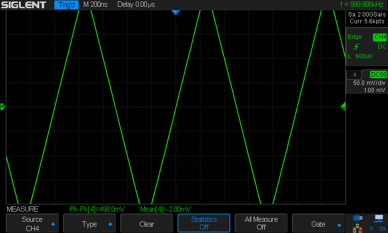
SDS2304X_Daynamic_500mVpp_50mV

Note that the peak to peak measurement is still correct (within tolerances), even though the screen height is only 400mV.

If we stop the acquisition and turn up the vertical gain setting to 100mV/div, we can see the full waveform, nothing misaligned, nothing clipped:


SDS2304X_Daynamic_500mVpp_100mV


So, this scope does know how to do the math, as it can do the same software offset adjustment with the frozen sweep samples (single-triggered), but it seems it is not doing it with the incoming sample data flow.  And because it has not corrected the incoming data, the shown values both in the running waveforms (except with GND-coupled input) and in the single-triggered frozen sweep can be also slightly wrong. In single-trigger view it is only calculating the "fine-tuned" offset change on top of the non-corrected sample data, it does not apply the correction at any point, even during this post-processing where it would have all the time it needs and then some.
The scope does not do any adjustments when in Run mode. There is no time for that either. It just collects ADC samples in the sample memory and then flushes out the whole bunch to the display every 40 milliseconds. The SDS2000(X) does manipulate the sample data in Average and Eres acquisition modes though, and this limits the usable Sample memory to a total of 28k and slows down the waveform update speed to something close to the screen update rate on top of that.

Note: this is different for the newer SDS1000X-E models, which do it in hardware and can use deep memory and reach full speed in these modes.

There is also no point in modifying the data in Stop mode all of a sudden. The scope just shows the very last acquisition in this mode, just as it has been displayed during Run (there it was not alone but together with numerous previous acquisitions).

Only when you alter the vertical position in Stop mode, it does some math to reposition the trace to where it’s supposed to be with the new offset – and usually the assumptions are correct, so you don’t see any major jump when starting Run mode again.

In any case, the shown samples do not have the fine-step offset shown to user (except in every 1 in 6 offset or so, EDIT: and no way to know which one of those 6 steps would give a physical offset that matches the shown offset) (and ignoring absolute accuracy, only considering the relative accuracy and resolution).  Either the scope should apply the corrective math (one signed 8-byte addition operation per sample) or let the user only adjust the offset with the actual resolution available (since it apparently can not be controlled as accurately as let to believe anyway). (I am also aware that likely the best offset step size in those lowest ranges would be about double of what the steps are doing now in 2mV/div sensitivity, I'd be fine with that.) Both solutions would end with samples with correct offset; one needs a tiny bit more calculations and gives smoother offset control, the other with visibly coarser offset control but matching what the analog side can actually do.
Yes, now we’re talking about a change request.

I agree that it would be better to display the actual values, but I think I can understand why it is the way it is now. The UI is kind of universal and defines a certain resolution for the offset control. Some low level driver has to translate that request to the actual hardware, which is just not capable of fulfilling it at the very high sensitivities in this particular case. The UI doesn’t know that and it would not be just a small change to implement that. A new API would be required for the UI to query the driver about the capabilities of the hardware and then the proper restrictions have to be applied. But at least it would not be out of the question to do that.

The other approach though, applying some software processing during run to make up for insufficient DAC resolution, is clearly not going to happen – I can smell that in advance ;)

(Note that the corrective addition does not need to be done with every single input sample, but only for shown samples, but then everything else needs to consider this dualism of having different "effective input sample offset" and "higher resolution visual offset". E.g. trigger levels would need to work with the same effective offset as the input data is being handled, but the levels must be shown in the same "visual offset" as the samples are shown with. So, the added complexity of such solution would be just asking for more bugs...  Adding an offset correction to every simple input data is simple, but it does need that one calculation, and there can be quite a number of samples coming in, is there enough processing resources in the system...)
There are no samples not showing on the screen. This is one of the points of the Siglent X-series scopes, that they don’t hide any real data and users can always see everything that has been captured at a glance. A single video frame on the screen, updated every 40 milliseconds, contains up to thousands of trigger events, and the entire sample memory is cramped into that display. Yes, many samples will overlap that way, but you’ll never miss a peak or glitch as long as the effective sample rate is high enough to capture it in the first place, and this is also why intensitiy grading works so well with these scopes.

You have just identified a number of impacts that a software correction of the input offset would have on other areas, like triggering and measurements, so it is not just an easy coffee-break change. But the biggest argument against such an implementation would be the impact on performance, as already stated before. Post processing every single Sample in a scope that can use up to a total of 280Mpts (with both ADCs active) is just not going to happen.

An additional question is related to that GND-coupled input. How can its offset be controlled in that 1LSB resolution? I'd have assumed that it would be simply a switched connection to ground at the AFE input (or similar), and thus should have the exact same normal analog side processing. Showing the internal noise and offset calibration errors, and those ~3LSB jumps with offset adjustment. But since GND-coupled input offsetting moves every 2 steps (1 LSB), something is very much different for them. Is the GND switched to the path after the analog offset injection and given all of the offset with digital "correction"? Or even later, just before ADC (as it does not need any gain either)? Or simply digital simulation (with tiny bit of simulated noise on it)?
I’ve already mentioned that at the beginning. Since the data from the acquisition are ignored in this coupling type, the scope has nothing to correct. It just draws a line at the position that is set by the vertical position control. It’s a pure graphical operation.

I for one don’t see any noise in GND mode, not even at the zoomed 1mV/div gain setting. But I admit that I do not know where exactly the switch is implemented. From some experiments, my first suspicion would be that simply the data transfer between ADC and sample buffer is stopped.

 
The following users thanked this post: rf-loop

Offline bugi

  • Regular Contributor
  • *
  • Posts: 249
  • Country: fi
  • Hobbyist using the ultra slow and unsure method
Re: Siglent's new product- SDS2000X Series
« Reply #140 on: October 14, 2018, 01:46:35 pm »
All that theory I already knew.
Sorry, but from your replies this is not always absolutely clear to me – and then there might be others coming across this thread who may actually find it useful to get the full explanations posted here. I don’t mean to bore anybody, but still prefer to provide complete information.
So for this posting I apologize in advance that I will write a lot of things that you probably know already ;)
No worries, by all means, indeed be thorough (I usually do just the same with my responses in similar situation, that is, when I can), it was just to let you know what info I already had when making my earlier replies. But I'm still (re)learning (as obvious from the hysteresis -case).

Quote
My addition to the theory section:
As long as there is headroom in the ADC (e.g. showing only 200 value range with 8-bit ADC which has total range of 256 steps), the "fine-tuning" of the offset (to within ADC's resolution, or actually even better than that if samples have enough bits) can be done with software/digital. (It can be done even with no ADC headroom, but then either the top or bottom end would have a bit of clipping.)

As an example: say, having settings where ADC resolution would correspond to exactly 1mV, but offset system provides only 10mV resolution, and we would like 6mV offset.  If the system then chooses the closest analog offset (10mV), the ADC gives values that are 4mV off the mark (too high offset). But the system knows that, so it can just subtract 4mV offset from every sample in digital/software, and now the final samples are offset by the desired 6mV.
You are right, it could be done that way – on a very different scope that is, one that would be slow like a turtle. ;)
Actually does not need to be slow (with proper hardware), but might not be cheap or easy, or possible with the tech in this scope. I was thinking such solutions like 15-20 years ago with DSP chips available back then, with IIRC just 8 parallel units capable of addition, though each could be independent, and half of them could do MACs, not just additions). These days it is nearly trivial considering all the parallel processing advancements - if one can choose the hardware, which obviously isn't the case here; the scope has what it has.


Quote
There is also no point in modifying the data in Stop mode all of a sudden. The scope just shows the very last acquisition in this mode, just as it has been displayed during Run (there it was not alone but together with numerous previous acquisitions).

Only when you alter the vertical position in Stop mode, it does some math to reposition the trace to where it’s supposed to be with the new offset – and usually the assumptions are correct, so you don’t see any major jump when starting Run mode again.
The latter part is where I see difference; it does not move the trace where it should be (considering the numeric offset value), but moves it relatively to the captured level. For example, I could take a single trace at the earlier -1.24mV offset level, then move the offset to the -1.04mV level (5 offset numeric steps up, two visible 1LSB steps on the view up), then if I press either another single capture or the auto trigger, the new samples appear back on the same lower level that I had at -1.24mV (or with any offset between that and -1.04mV). It is not a major jump, per se, but still a jump.

Basically, the uncertainty even on relative error of the offset is around that 3LSB.

So, either the stop mode could use correct fine offset and thus cause a small visible jump from run mode to stop mode and have as good a visible offset level as possible, or work like it does now, having a similar jump from stop mode when taking new sweep or switching to running mode and having unknown small amount of error in the shown offset vs. shown signal.


Quote
There are no samples not showing on the screen. This is one of the points of the Siglent X-series scopes, that they don’t hide any real data and users can always see everything that has been captured at a glance. A single video frame on the screen, updated every 40 milliseconds, contains up to thousands of trigger events, and the entire sample memory is cramped into that display. Yes, many samples will overlap that way, but you’ll never miss a peak or glitch as long as the effective sample rate is high enough to capture it in the first place, and this is also why intensitiy grading works so well with these scopes.

You have just identified a number of impacts that a software correction of the input offset would have on other areas, like triggering and measurements, so it is not just an easy coffee-break change. But the biggest argument against such an implementation would be the impact on performance, as already stated before. Post processing every single Sample in a scope that can use up to a total of 280Mpts (with both ADCs active) is just not going to happen.
The maximum rate of incoming samples is, I think 4Gs/s (2+2). A modern cheap DSP tech or a parallel processing unit in a CPU can handle that trivially. E.g. 64 byte size additions in parallel (and the other operands are the same number, so no bandwidth wasted in moving varying other operands, only for the samples), 62.5MHz rate is enough. (Even original Pentiums MMX stuff was close to handle that, 20 years ago.) As I mentioned above, I was musing this kind of stuff back then (not for scope samples but SDR processing). Not quite as trivial back then, or needed a chip that cost hundreds of $$$.

However, the alternate version does not need to process all samples individually; it could first process them to the visual data (a maximum of 640x400 in pixels in separate temporary layer), then translate those pixels by the calculated screen-space offset. About two orders of magnitude less of calculations. However, there would be that complexity then. Well, since it does need to do the addition (and other stuff) to place to samples into pixels in the first place, it is just a matter of changing that one value.... see the paragraph after the next one.

Also, even if calculating the offset correction for each sample in stop mode, as I said, there is (usually) ample time, relatively speaking. A human=slow user is looking at it, so it does not have to be "instant", just faster than what it takes for a user to "process" the data he is seeing.

And anyway, the scope is doing that offset calculation stuff already in stop mode, just with the slightly "wrong" offset, so processing time obviously hasn't been a problem (in that mode). All it would need to do is to add the internal corrective value to the numeric offset number before doing what it is already doing. (Though, as mentioned, this would result in the "jump" to happen when switching from the running mode to stop mode, and running mode still showing slightly wrong offset.)


Quote
I for one don’t see any noise in GND mode, not even at the zoomed 1mV/div gain setting. But I admit that I do not know where exactly the switch is implemented. From some experiments, my first suspicion would be that simply the data transfer between ADC and sample buffer is stopped.
See the attachment, using single trigger, 1V/div (it looks similar at any sensitivity, but they are samples and affected by sensitivity changes afterwards).  Whether to call it noise or something else, I don't know, but it certainly isn't a flat line.
 

Offline rf-loop

  • Super Contributor
  • ***
  • Posts: 4086
  • Country: fi
  • Born in Finland with DLL21 in hand
Re: Siglent's new product- SDS2000X Series
« Reply #141 on: October 14, 2018, 04:39:11 pm »
See the attachment, using single trigger, 1V/div (it looks similar at any sensitivity, but they are samples and affected by sensitivity changes afterwards).  Whether to call it noise or something else, I don't know, but it certainly isn't a flat line.

Siglent SDS2000X is not alone with this. Same with SDS1000X-E series and SDS2000 (no X).
Input coupling "to GND" still have some changes in the sample queue. Also if all ADC's works non interleaved mode. (all channels on).
I drive a LEC (low el. consumption) BEV car. Smoke exhaust pipes - go to museum. In Finland quite all electric power is made using nuclear, wind, solar and water.

Wises must compel the mad barbarians to stop their crimes against humanity. Where have the wises gone?
 

Offline Performa01

  • Super Contributor
  • ***
  • Posts: 1629
  • Country: at
Re: Siglent's new product- SDS2000X Series
« Reply #142 on: October 15, 2018, 01:34:24 pm »
Actually does not need to be slow (with proper hardware), but might not be cheap or easy, or possible with the tech in this scope. I was thinking such solutions like 15-20 years ago with DSP chips available back then, with IIRC just 8 parallel units capable of addition, though each could be independent, and half of them could do MACs, not just additions). These days it is nearly trivial considering all the parallel processing advancements - if one can choose the hardware, which obviously isn't the case here; the scope has what it has.
Rumor has it that the SDS2000X uses an Analog Devices 400MHz Blackfin DSP. This is a capable DSP for sure, but has to do a lot of things after all. I cannot tell any internals, so the tiny hint that resources are limited with this architecture shall suffice.

I have already mentioned the newer SDS1000X-E series which has the processing for Average and Eres implemented in hardware, so there is almost no slowdown – but still there is some, even though the max. memory depth is limited to 1.4Mpts. This platform is based on the Xilinx Zync SOC, which is a very powerful architecture and can handle a huge memory. Anyway, the base philosophy has been kept the same – I have not thoroughly checked yet, but would be very surprised if offset were handled any different than in the SDS2k.

The maximum rate of incoming samples is, I think 4Gs/s (2+2). A modern cheap DSP tech or a parallel processing unit in a CPU can handle that trivially. E.g. 64 byte size additions in parallel (and the other operands are the same number, so no bandwidth wasted in moving varying other operands, only for the samples), 62.5MHz rate is enough. (Even original Pentiums MMX stuff was close to handle that, 20 years ago.) As I mentioned above, I was musing this kind of stuff back then (not for scope samples but SDR processing). Not quite as trivial back then, or needed a chip that cost hundreds of $$$.
Even though it might seem trivial if looked at in isolation, we should not forget that this is not the only task for this DSO. Anyway, according to my previous hint, we won't get any additional bells and whistles for the SDS2000(X). Even if we could, I'd certainly have different priorities, e.g. long memory for Average and Eres – because other than some offset inaccuracy at the highest sensitivities, we run into serious (aliasing) troubles pretty easily with just 28kpts total for those acquisition modes.

However, the alternate version does not need to process all samples individually; it could first process them to the visual data (a maximum of 640x400 in pixels in separate temporary layer), then translate those pixels by the calculated screen-space offset. About two orders of magnitude less of calculations. However, there would be that complexity then. Well, since it does need to do the addition (and other stuff) to place to samples into pixels in the first place, it is just a matter of changing that one value.... see the paragraph after the next one.
It is 700 x 400 screen pixels btw.

Without knowing the internal architecture, we could speculate all day how things could be done differently. No one at Siglent will seriously consider a radical change in the system architecture just for bypassing a minor issue, that could easily be addressed by just fitting a higher resolution DAC for the offset control.

I'm not in my lab anymore until next weekend, so I cannot look right now how the newer SDS1000X-E handle vertical position changes down at their highest sensitivities. There we have even +/-2V offset and one LSB in the 500µV range is just 20µV. We’d need a DAC capable of 200k steps, some 18 bits…

Maybe rf-loop is reading this and could have a look?

And anyway, the scope is doing that offset calculation stuff already in stop mode, just with the slightly "wrong" offset …
 
I have stated it already - Stop mode is completely different. It only shows a single acquisition and no new data to be combined with the existing ones and no building up of millions of data points for a single video frame every 40ms. Consequently, there is also no intensity grading in Stop mode. All in all, it’s not only very different but also a lot easier.

See the attachment, using single trigger, 1V/div (it looks similar at any sensitivity, but they are samples and affected by sensitivity changes afterwards).  Whether to call it noise or something else, I don't know, but it certainly isn't a flat line.
Yes, just like you I found the obvious answer while taking a walk. I’m convinced now that the GND coupling is simulated by shutting off the VGA output, not the ADC. This could even be a regular function of the VGA. In any case it is done after the input buffer and the internal offset voltage doesn’t come into play here anymore.

The difference between no input signal and GND coupling is almost always there, and quite obviously the scope tries to apply some offset correction to the GND coupling as well, as some have observed the real input providing a better zero reading than the GND coupled trace at times.

All in all I haven’t spent much time in the past to clear such phenomena up, simply because it did never matter for my practical work and I have never used GND coupling anyway – why should I? This is just a weird relict from old analog scopes in my book. There we needed it for quick trace nulling, but on a modern DSO we have auto-cal for that. I know, this is not the point here in this discussion; but it explains why I never bothered to find out what the scope exactly does in GND coupling mode. Yet I’m absolutely sure it does not get any real input signal anymore, also not the internal generated DC offset.

What we can see in stop mode is some granular noise from the ADC, independent of the vertical gain setting, because the gain of the VGA doesn’t have any impact when it is in “output shutdown” mode.
 

Offline bugi

  • Regular Contributor
  • *
  • Posts: 249
  • Country: fi
  • Hobbyist using the ultra slow and unsure method
Re: Siglent's new product- SDS2000X Series
« Reply #143 on: October 15, 2018, 02:02:58 pm »
And anyway, the scope is doing that offset calculation stuff already in stop mode, just with the slightly "wrong" offset …
 
I have stated it already - Stop mode is completely different. It only shows a single acquisition and no new data to be combined with the existing ones and no building up of millions of data points for a single video frame every 40ms. Consequently, there is also no intensity grading in Stop mode. All in all, it’s not only very different but also a lot easier.
I understood that it is different, and was trying to emphasize that in that situation, it could show the signal with the corrected offset down to that 1LSB ~ 2 pixels ~2 steps of vertical offset with no extra effort. But it does not. And what the differences in the use would be between current way and the corrected way I mentioned there earlier.

But probably the most consistent way would be to simply have the little bit of extra code to handle bigger than 1 LSB offset stepping already in the control UI, i.e. let the offset step with the same amount as the circuitry can do. Maybe some day, maybe not. This "issue" certainly won't stop me using the scope :)  (Just have to write a note on it to remind me of it. And of the hysteresis :P)
 

Offline rf-loop

  • Super Contributor
  • ***
  • Posts: 4086
  • Country: fi
  • Born in Finland with DLL21 in hand
Re: Siglent's new product- SDS2000X Series
« Reply #144 on: October 16, 2018, 08:41:21 am »


I have already mentioned the newer SDS1000X-E series which has the processing for Average and Eres implemented in hardware, so there is almost no slowdown – but still there is some, even though the max. memory depth is limited to 1.4Mpts. This platform is based on the Xilinx Zync SOC, which is a very powerful architecture and can handle a huge memory. Anyway, the base philosophy has been kept the same – I have not thoroughly checked yet, but would be very surprised if offset were handled any different than in the SDS2k.

I'm not in my lab anymore until next weekend, so I cannot look right now how the newer SDS1000X-E handle vertical position changes down at their highest sensitivities. There we have even +/-2V offset and one LSB in the 500µV range is just 20µV. We’d need a DAC capable of 200k steps, some 18 bits…

Maybe rf-loop is reading this and could have a look?


Disclaimer: the following are not facts, but a mixture of fact and fiction due to some "reasons":
SDS1004X-E

500uV/div maximum input offset is -2V to +2V
Displayed signal trace minimum vertical position increment is 20uV (signal ADC resolution is 20uV when 500uV/div).
If whole range with full resolution is done with offset DAC it need have 18 bit resolution but it is not.
I have watched AutoCal increments when scope is in warming phase and AutoCal is ON. Increment looks like  around 240uV but really difficult to say exactly due to noise including 1/f noise what makes it bit difficult. So I can say one OffsDAC increment is  240uV +/- 40uV.

But, it is not whole truth. Offset can adjust 20uV steps for trace displayed (adjustment displayed numbers step is 10uV but trace moves only after 2 steps, 20uV). But these fine steps are not offset DAC steps. It use  other method for these fine steps between offset DAC steps. Of course this method is not perfectly accurate due to many reasons including----and so on.
I drive a LEC (low el. consumption) BEV car. Smoke exhaust pipes - go to museum. In Finland quite all electric power is made using nuclear, wind, solar and water.

Wises must compel the mad barbarians to stop their crimes against humanity. Where have the wises gone?
 
The following users thanked this post: Performa01

Offline Performa01

  • Super Contributor
  • ***
  • Posts: 1629
  • Country: at
Re: Siglent's new product- SDS2000X Series
« Reply #145 on: October 16, 2018, 09:01:31 am »
Thank you very much rf-loop for your checks and comments!

Yes, it would be hard to believe that there is actually an 18bit DAC fitted.

So it seems Siglent have taken advantage on the powerful platform and actually implemented some "offset fine adjust block" in hardware (FPGA) to cope with both the higher offset range and higher sensitivity of these scopes.

« Last Edit: October 16, 2018, 09:06:58 am by Performa01 »
 

Offline rf-loop

  • Super Contributor
  • ***
  • Posts: 4086
  • Country: fi
  • Born in Finland with DLL21 in hand
Re: Siglent's new product- SDS2000X Series
« Reply #146 on: October 16, 2018, 10:11:35 am »


So it seems Siglent have taken advantage on the powerful platform and actually implemented some "offset fine adjust block" in hardware (FPGA) to cope with both the higher offset range and higher sensitivity of these scopes.

SDS2k and 2kX have true 2mV/div. It have very different hardware what is in SDS1kX-E.

Imho, this what is in SDS1004X-E is also good in this class. But it also need remember it have true 500uV/div and for it OffsetDAC resolution is bit  borderline. (but then we remember price class... there need do compromises)

Main ADC and offset DAC have different scale and Vref and analog offset circuits and analog attenuators, amplifiers etc all they are individuals in front end, they are what they are.

If someone want these circuits are matched and calibrated so that all matches exactly and perfectly so that example offset DAC increments are match exactly with some integer amount of main ADC step I will recommend to buy one way ticket to "Ms Lisa's wonderland".

World (in this case input signal) is (in this context) analog and also digital oscilloscope is analog until signal is digitized...

How perfect it need be in practice. Of course it differ depending for what we are using it. But always need think, how accurate and perfect we really need and what is in class... "nice to have"

There is true analog signal what we want test. Ok, we connect DUT this signal what we want look to oscilloscope input. But just we make contact to this signal and there is not anymore this original signal. Not even in this circuit what we are testing. The signal to be measured changes when we measure. 

Ok, this unknown amount changed signal come to oscilloscope  input.  Then this unknown analog signal added with unknown amount of errors is handled in front end and it add some amount of errors to signal. After then this signal with all errors is digitized and again added with some more errors.
Then we display this result what include some unknown original signal what also we have destroyed more or less, then added with some oscilloscope added errors so that we still believe it somehow imitate more or less accurate original untouched signal in DUT. (...and oscilloscope signal offset setting is in analog side including all its errors... ).

SDS1004X-E.
If Offset have around 240uV increments and offset range is 4V (+/-2V) it means that OffsDAC need least  14bit.
But if it is 14 bit DAC and step is 240uV then its range is not enough. If step is 260uV even then range is just over 4V (4.26V). There need remember that there is several analog components just installed in production line. After then there need be enough room for factory calibration from scratch and after then still room for years of components drifting for selfcal or true cal.
Selfcal resolution for vertical offset adjust voltage is just this DAC resolution. If increment is 250uV  then whole range give 4096 room for 4000. If I think this,  I feel it is bit too narrow for mass production (if it works somehow as I "believe") So, it is perhaps more than just 14 bit...
I drive a LEC (low el. consumption) BEV car. Smoke exhaust pipes - go to museum. In Finland quite all electric power is made using nuclear, wind, solar and water.

Wises must compel the mad barbarians to stop their crimes against humanity. Where have the wises gone?
 

Offline Performa01

  • Super Contributor
  • ***
  • Posts: 1629
  • Country: at
Re: Siglent's new product- SDS2000X Series
« Reply #147 on: October 16, 2018, 11:07:31 am »
SDS1004X-E.
If Offset have around 240uV increments and offset range is 4V (+/-2V) it means that OffsDAC need least  14bit.
But if it is 14 bit DAC and step is 240uV then its range is not enough. If step is 260uV even then range is just over 4V (4.26V). There need remember that there is several analog components just installed in production line. After then there need be enough room for factory calibration from scratch and after then still room for years of components drifting for selfcal or true cal.
Selfcal resolution for vertical offset adjust voltage is just this DAC resolution. If increment is 250uV  then whole range give 4096 room for 4000. If I think this,  I feel it is bit too narrow for mass production (if it works somehow as I "believe") So, it is perhaps more than just 14 bit...

Then we should not forget that any DAC has INL and also DNL errors, and for the higher resolution DACs this error inevitably becomes substantial.

This is probably the main reason why it is so hard to determine the true physical offset resolution when just watching the scope doing its quick-cal. With an DNL error of just +/-0.5LSB (not at all uncommon even for very good DACs), one LSB step could actually be anything between 100 and 300µV if for example one LSB would ideally be 200µV...


Offline rf-loop

  • Super Contributor
  • ***
  • Posts: 4086
  • Country: fi
  • Born in Finland with DLL21 in hand
Re: Siglent's new product- SDS2000X Series
« Reply #148 on: October 16, 2018, 04:47:44 pm »
SDS1004X-E.
If Offset have around 240uV increments and offset range is 4V (+/-2V) it means that OffsDAC need least  14bit.
But if it is 14 bit DAC and step is 240uV then its range is not enough. If step is 260uV even then range is just over 4V (4.26V). There need remember that there is several analog components just installed in production line. After then there need be enough room for factory calibration from scratch and after then still room for years of components drifting for selfcal or true cal.
Selfcal resolution for vertical offset adjust voltage is just this DAC resolution. If increment is 250uV  then whole range give 4096 room for 4000. If I think this,  I feel it is bit too narrow for mass production (if it works somehow as I "believe") So, it is perhaps more than just 14 bit...

Then we should not forget that any DAC has INL and also DNL errors, and for the higher resolution DACs this error inevitably becomes substantial.

This is probably the main reason why it is so hard to determine the true physical offset resolution when just watching the scope doing its quick-cal. With an DNL error of just +/-0.5LSB (not at all uncommon even for very good DACs), one LSB step could actually be anything between 100 and 300µV if for example one LSB would ideally be 200µV...

This was reason why it take many hours watching it with many different offsets and starting scope from cold and warm several times and including also some previous  observations  including even notification what I made to Siglent soon after first SDS1000X was launched (at this time offset handling was different)

Now its is acceptable good, but not perfect (for 500uV/div) and who even think it can be perfect. This day do not come never - if someone is waiting it. Least bugs need repair first if or when they exist, cosmetics are quite low in priority. We need just accept (offset) it is tiny bit fuzzy but good.
What is real application where this (offset) accuracy is not enough in real life with this price range oscilloscope - I do not know any serious.
But, this was for offtopic model SDS1000X-E. ;)
« Last Edit: October 16, 2018, 04:50:20 pm by rf-loop »
I drive a LEC (low el. consumption) BEV car. Smoke exhaust pipes - go to museum. In Finland quite all electric power is made using nuclear, wind, solar and water.

Wises must compel the mad barbarians to stop their crimes against humanity. Where have the wises gone?
 

Offline Tsippaduida

  • Contributor
  • Posts: 15
  • Country: fi
Re: Siglent's new product- SDS2000X Series
« Reply #149 on: October 18, 2018, 06:15:25 pm »
Just to conform to Performa01's note earlier, this is exellent discussion for us silent readers. I use my scope (SDS2104X) infrequently and I'm quite a newbie with it, but for me it has served well. Haven't run into tricky situations like bugi has. Reading this kind of lengthy discussion with samples and thorough explanations gives me background which will undoubtedly be of use some day.
 
The following users thanked this post: Performa01

Online tautech

  • Super Contributor
  • ***
  • Posts: 28310
  • Country: nz
  • Taupaki Technologies Ltd. Siglent Distributor NZ.
    • Taupaki Technologies Ltd.
Re: Siglent's new product- SDS2000X Series
« Reply #150 on: March 27, 2019, 05:02:31 am »
Firmware update for SDS2000X models.

Version 1.2.2.2R19
3.7 MB
https://www.siglentamerica.com/download/8432/

Changelog
1. Supported reading out data of digital channels by SCPI commands
Avid Rabid Hobbyist
Siglent Youtube channel: https://www.youtube.com/@SiglentVideo/videos
 

Offline jemangedeslolos

  • Frequent Contributor
  • **
  • Posts: 386
  • Country: fr
Re: Siglent's new product- SDS2000X Series
« Reply #151 on: May 04, 2019, 10:26:09 am »
Hello,

If someone is interested, I sell mine here at a good price I think : https://www.eevblog.com/forum/buysellwanted/fs-used-siglent-sds2204x-full-option-oscilloscope/


Share me

Digg  Facebook  SlashDot  Delicious  Technorati  Twitter  Google  Yahoo
Smf