Author Topic: Tektronix 2465B oscilloscope teardown  (Read 665805 times)

0 Members and 4 Guests are viewing this topic.

Offline med6753

  • Super Contributor
  • ***
  • Posts: 11313
  • Country: us
  • Tek nut
Re: Tektronix 2465B oscilloscope teardown
« Reply #1150 on: August 20, 2018, 09:22:13 pm »
Another useful bit of information at this point while looking for a 246x scope would be if there is an error code specific to an instrument that has lost its calibration constants? Is there such error message, or is there anything else I would need to look out for to know for sure that the calibration is gone? Thanks.

You can download a copy of the 2465A service manual here...

https://elektrotanya.com/tektronix_2465a_2467.pdf/download.html

Starting at section 6-10 it lists all the diagnostic routines.
An old gray beard with an attitude.
 

Offline emece67

  • Frequent Contributor
  • **
  • !
  • Posts: 614
  • Country: 00
Re: Tektronix 2465B oscilloscope teardown
« Reply #1151 on: September 03, 2018, 04:29:52 pm »
.
« Last Edit: August 19, 2022, 05:51:07 pm by emece67 »
 

Offline med6753

  • Super Contributor
  • ***
  • Posts: 11313
  • Country: us
  • Tek nut
Re: Tektronix 2465B oscilloscope teardown
« Reply #1152 on: September 03, 2018, 05:25:46 pm »

But it is the Lithium cell what worries me. Its timestamp is from 1988Q1, so it has more than 30 years on it. Its voltage is now 3.67 V.

Does anybody changed this battery not losing the battery cal. data? I'm thinking on powering the RAM from an external battery; remove the old one; solder a pair of wires to the PCB holes of the removed battery; and connect a new battery to such wires, in case I need to replace the battery again in the future. Comments on this? Any other EEVblog-approved procedure?

Also, the battery (a Eagle-Picher Keeper LPC-7P) seems to be unobtanium in EU, any replacement?

Thanks a lot & regards.

Yes, that's been done. A backup voltage provided while the battery is changed out. If I recall correctly that procedure is buried somewhere way back in this thread. Got a few hours to do some reading/searching?  :-DD
An old gray beard with an attitude.
 

Offline AMR Labs

  • Frequent Contributor
  • **
  • Posts: 258
  • Country: an
Re: Tektronix 2465B oscilloscope teardown
« Reply #1153 on: September 03, 2018, 05:30:08 pm »
Thanks Med! Been kind of busy with other stuff lately and didn't have much time to check back in here until today. Downloading manual now.

Another useful bit of information at this point while looking for a 246x scope would be if there is an error code specific to an instrument that has lost its calibration constants? Is there such error message, or is there anything else I would need to look out for to know for sure that the calibration is gone? Thanks.

You can download a copy of the 2465A service manual here...

https://elektrotanya.com/tektronix_2465a_2467.pdf/download.html

Starting at section 6-10 it lists all the diagnostic routines.
 

Offline cheeseit

  • Regular Contributor
  • *
  • Posts: 168
  • Country: dk
Re: Tektronix 2465B oscilloscope teardown
« Reply #1154 on: September 03, 2018, 05:35:02 pm »
How-to here and battery here
 
The following users thanked this post: factory, emece67, tonedeak99

Offline AMR Labs

  • Frequent Contributor
  • **
  • Posts: 258
  • Country: an
Re: Tektronix 2465B oscilloscope teardown
« Reply #1155 on: September 03, 2018, 05:37:14 pm »

But it is the Lithium cell what worries me. Its timestamp is from 1988Q1, so it has more than 30 years on it. Its voltage is now 3.67 V.

Does anybody changed this battery not losing the battery cal. data? I'm thinking on powering the RAM from an external battery; remove the old one; solder a pair of wires to the PCB holes of the removed battery; and connect a new battery to such wires, in case I need to replace the battery again in the future. Comments on this? Any other EEVblog-approved procedure?

Also, the battery (a Eagle-Picher Keeper LPC-7P) seems to be unobtanium in EU, any replacement?

Thanks a lot & regards.

Yes, that's been done. A backup voltage provided while the battery is changed out. If I recall correctly that procedure is buried somewhere way back in this thread. Got a few hours to do some reading/searching?  :-DD

Yes I saw it somewhere back in those 46 previous pages. As I recall that in essence the procedure is that the yellow tantalum capacitor next to the battery is temporarily removed, and the leads of a 2xAA cell battery holder is soldered in place on the capacitor pads, and be sure to watch correct polarity. The two AA batteries will power the RAM chip while you exchange the Lithium battery. Once done verify everything looks good, remove the 2xAA battery holder leads, and reinstall the tantalum capacitor.
« Last Edit: September 03, 2018, 05:40:25 pm by AMR Labs »
 
The following users thanked this post: emece67

Offline james_s

  • Super Contributor
  • ***
  • Posts: 21611
  • Country: us
Re: Tektronix 2465B oscilloscope teardown
« Reply #1156 on: September 03, 2018, 05:53:15 pm »
Why remove the capacitor? Can't you just tack solder some wires to the pads with the capacitor in place?
 

Offline AMR Labs

  • Frequent Contributor
  • **
  • Posts: 258
  • Country: an
Re: Tektronix 2465B oscilloscope teardown
« Reply #1157 on: September 03, 2018, 06:02:38 pm »
Why remove the capacitor? Can't you just tack solder some wires to the pads with the capacitor in place?

Not sure, maybe its easier (possibly also more secure) to firmly solder the wires of the battery holder on the pads on the component side when the capacitor is removed, so as to keep those wires out of the way, while one would be working on the foil side to exchange the Lithium cell. I have never done the procedure, but I think it would make sense. Tack soldering wires sometimes work themselves loose. Please feel free to correct me if I am wrong.
 

Offline james_s

  • Super Contributor
  • ***
  • Posts: 21611
  • Country: us
Re: Tektronix 2465B oscilloscope teardown
« Reply #1158 on: September 03, 2018, 06:07:56 pm »
I think it's worth looking closely for the best method, something you have to be careful about is accidentally shorting the two nodes together which will result in a power glitch that will likely corrupt the memory. I would be nervous about the possibility of shorting something with the soldering iron while trying to remove and reinstall that part.
 

Offline cheeseit

  • Regular Contributor
  • *
  • Posts: 168
  • Country: dk
Re: Tektronix 2465B oscilloscope teardown
« Reply #1159 on: September 03, 2018, 06:16:49 pm »
Removing it is unnecessary, and reduces the risk of lifting pads or damaging the board. With proper and careful solder work (use flux) nothing works itself lose, provided you don't yank the wires or throw the board around. You can use kapton tape to secure the wires to the board, and perhaps to shield the areas around the solder points. See the guide I provided, it is pretty easy.
 

Offline emece67

  • Frequent Contributor
  • **
  • !
  • Posts: 614
  • Country: 00
Re: Tektronix 2465B oscilloscope teardown
« Reply #1160 on: September 04, 2018, 10:01:27 pm »
.
« Last Edit: August 19, 2022, 05:51:15 pm by emece67 »
 

Offline tkamiya

  • Super Contributor
  • ***
  • Posts: 2178
  • Country: us
Re: Tektronix 2465B oscilloscope teardown
« Reply #1161 on: September 05, 2018, 12:21:38 am »
Replaced my memory chip with Dallas compatible with socket.  Somehow, in the process, something got knocked lose and it won't even boot.  Took it apart and put it together, got back to where it was before.  04 11 error again.  I guess someone else's cal data wasn't close enough.  I'm somewhat encouraged that someone managed to cal it close enough with even an analog function generator.


Why can't I have TEN working scopes?  Waaaaaaaaa!  (I feel better now)
 

Offline emece67

  • Frequent Contributor
  • **
  • !
  • Posts: 614
  • Country: 00
Re: Tektronix 2465B oscilloscope teardown
« Reply #1162 on: September 13, 2018, 06:43:34 pm »
.
« Last Edit: August 19, 2022, 01:58:26 pm by emece67 »
 

Offline emece67

  • Frequent Contributor
  • **
  • !
  • Posts: 614
  • Country: 00
Re: Tektronix 2465B oscilloscope teardown
« Reply #1163 on: September 17, 2018, 12:23:43 pm »
.
« Last Edit: August 19, 2022, 05:52:02 pm by emece67 »
 

Offline SoundTech-LG

  • Frequent Contributor
  • **
  • Posts: 788
  • Country: us
Re: Tektronix 2465B oscilloscope teardown
« Reply #1164 on: September 17, 2018, 07:12:33 pm »
Hi again,

Finally managed to fix it. As there was no image at all, but the controls seem operative, I decided to check the HV board. Soon noticed that all HV voltages were dead, because the HV oscillator was also dead, as the unregulated -15 V tension was not present. Such voltage comes from the A2A1 regulator board via the J121 connector in the center of the image.


The problem was that I inserted the connector badly, in such a way that pin 1 from the PCB (the unregulated -15 V) was not inside the plastic connector, but below it  |O, where it cannot be seen . This was possible (apart for my clumsiness) because pin 2 is not present, so it is possible to push the connector slightly tilted, so pin 1 goes outside its place.

The unregulated -15 V source seems not to be used in any place, but in the HV oscillator, and it is also not monitored by the processor, so the remaining circuitry worked flawlessly and all tests passed OK.

It's working now, waiting for the AA sized Li-SOCl2 cell I will use to replace the PCB mounted RAM backup battery.

Regards.


More proof that 9 times out of 10 when you discover a new problem after any work you have done, it's time to carefully inspect the work. Has happened to me more than once on 2467B work. Pulled out a hidden connector while lifting out the Option 06 PCBA (Counter/Timer/Trigger), took a while to find that one.
 

Offline med6753

  • Super Contributor
  • ***
  • Posts: 11313
  • Country: us
  • Tek nut
Re: Tektronix 2465B oscilloscope teardown
« Reply #1165 on: September 18, 2018, 12:49:04 am »
Hi again,

Finally managed to fix it. As there was no image at all, but the controls seem operative, I decided to check the HV board. Soon noticed that all HV voltages were dead, because the HV oscillator was also dead, as the unregulated -15 V tension was not present. Such voltage comes from the A2A1 regulator board via the J121 connector in the center of the image.


The problem was that I inserted the connector badly, in such a way that pin 1 from the PCB (the unregulated -15 V) was not inside the plastic connector, but below it  |O, where it cannot be seen . This was possible (apart for my clumsiness) because pin 2 is not present, so it is possible to push the connector slightly tilted, so pin 1 goes outside its place.

The unregulated -15 V source seems not to be used in any place, but in the HV oscillator, and it is also not monitored by the processor, so the remaining circuitry worked flawlessly and all tests passed OK.

It's working now, waiting for the AA sized Li-SOCl2 cell I will use to replace the PCB mounted RAM backup battery.

Regards.

Good deal on finding your issue. Once you get your battery issues sorted out I strongly recommend re-capping the PSU. While I'm typically the type that takes the path "if it ain't broke, don't fix it" in the case of the 2465 PSU I'd rather be proactive. Troubleshooting those boards installed as they are can be a real PITA. And you can't power them outside the scope unless you build a load rack. So prevention seems to make sense. I think you mentioned before that your 2465B has low power on hours. That's fine but in the life of a capacitor you have to think in terms of total elapsed time. In this case we are talking 25-30 years which is old.

I've done two 2465's without any real issues. The last one I did I documented the entire process starting at post 1091. If you work slowly and carefully the most your scope will be out of action is 2 days. And it was totally worth the effort.
An old gray beard with an attitude.
 

Offline tggzzz

  • Super Contributor
  • ***
  • Posts: 19494
  • Country: gb
  • Numbers, not adjectives
    • Having fun doing more, with less
There are lies, damned lies, statistics - and ADC/DAC specs.
Glider pilot's aphorism: "there is no substitute for span". Retort: "There is a substitute: skill+imagination. But you can buy span".
Having fun doing more, with less
 
The following users thanked this post: worsthorse

Offline med6753

  • Super Contributor
  • ***
  • Posts: 11313
  • Country: us
  • Tek nut
Re: Tektronix 2465B oscilloscope teardown
« Reply #1167 on: September 18, 2018, 11:39:59 am »
See http://www.condoraudio.com/wp-content/uploads/Projects/Tektronix-2465B-Oscilloscope-Restoration-Repair.pdf

I ran across that article years ago after getting the 2465 DMS and started searching for information. I also joined the Tek Yahoo Group. It was clear from that article plus what I learned in the group that re-capping the PSU in the 24XX series was a smart investment. It certainly worked for me in that the 2465 DMS has not had any sort of crap out since re-capping (Knock on wood :-DD). And since getting the 2nd 2465 earlier this year I've done the same. 
An old gray beard with an attitude.
 
The following users thanked this post: worsthorse

Offline emece67

  • Frequent Contributor
  • **
  • !
  • Posts: 614
  • Country: 00
Re: Tektronix 2465B oscilloscope teardown
« Reply #1168 on: September 18, 2018, 09:22:44 pm »
.
« Last Edit: August 19, 2022, 02:03:15 pm by emece67 »
 

Offline AMR Labs

  • Frequent Contributor
  • **
  • Posts: 258
  • Country: an
Re: Tektronix 2465B oscilloscope teardown
« Reply #1169 on: September 22, 2018, 04:11:23 am »
Hi all,

Just started to open my pristine 2465B for a recap and cal. backed memory update, just to discover that mine has the old style A5 board (insertion components) that, to hold the cal. data, has a separate RAM chip and a PCB mounted Lithium battery, as seen here:


Interesting, what serial number range is your scope? That would probably the best option to look for.
 

Offline med6753

  • Super Contributor
  • ***
  • Posts: 11313
  • Country: us
  • Tek nut
Re: Tektronix 2465B oscilloscope teardown
« Reply #1170 on: October 01, 2018, 02:12:16 am »
This latest teardown will cover the heavily optioned 24XX such as the 2465 DMS which have options such as DMM and Counter/Trigger. It is a supplement and an addition to the vanilla 2465 teardown I documented in this thread back in July. My reasons for this supplement are two fold. First, the teardown of these beasts to either re-cap to PSU or service the fan motor is much more complex. And second, the fan motor in my 2465 DMS has developed a death screech and I need to pull the motor and service it.

The candidate. The lower 2465 DMS. The top 2465 was the subject of the teardown in July for the PSU. The PSU in the 2465 DMS was done 2 years ago and at that time the fan motor was sometimes noisy but usually quieted down after about 20 minutes or so. In retrospect I should have serviced it then because now I have no choice but to rip it apart again. But the benefit is others will see how it's done and how much more complex it is. This 2465 DMS has the following options:

Option 01: 4.5 digit DMM
Option 09: Counter/Trigger/Timer with 17-bit Word Recognizer
Option 10: GPIB Interface


On the surface it doesn't seem like a lot but in reality there is a lot of additional circuit boards and interconnects as this teardown will reveal. After all, we are dealing with 1980's technology with much less device density which results in higher component count. So the first section we'll start with the cage fan and DMM board removal. Section 2 will deal with the top plate removal and all the interconnects. Section 3 will deal with the fan motor itself and reassembly.


Once the covers are removed the first order of business is the cage fan if you have an older 2465. Newer 2465A and B have a computer type fan so you can skip this part. For more complete info on how to remove this cage fan see here:

https://www.eevblog.com/forum/testgear/tektronix-2465b-oscilloscope-teardown/msg1658102/#msg1658102


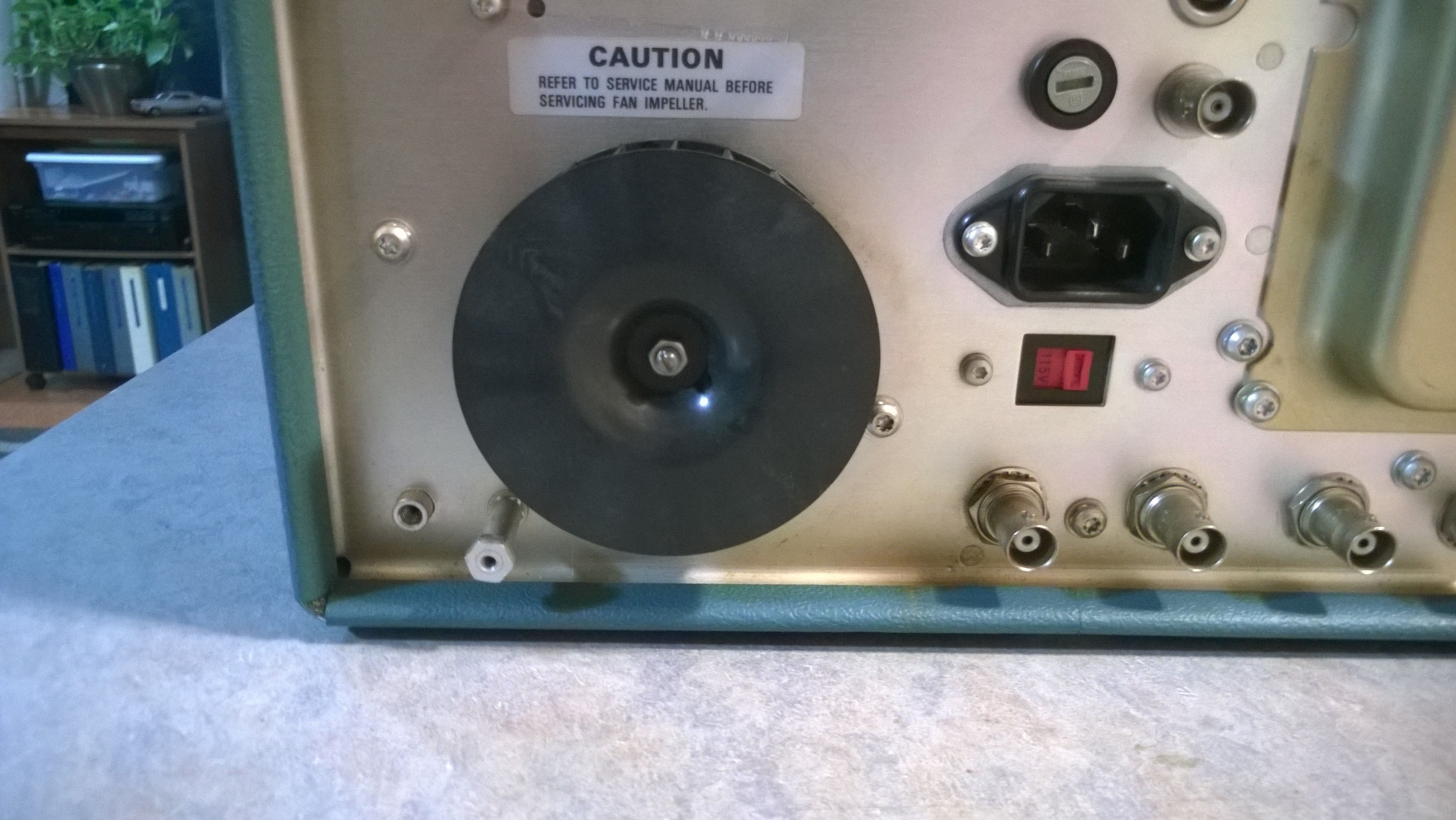
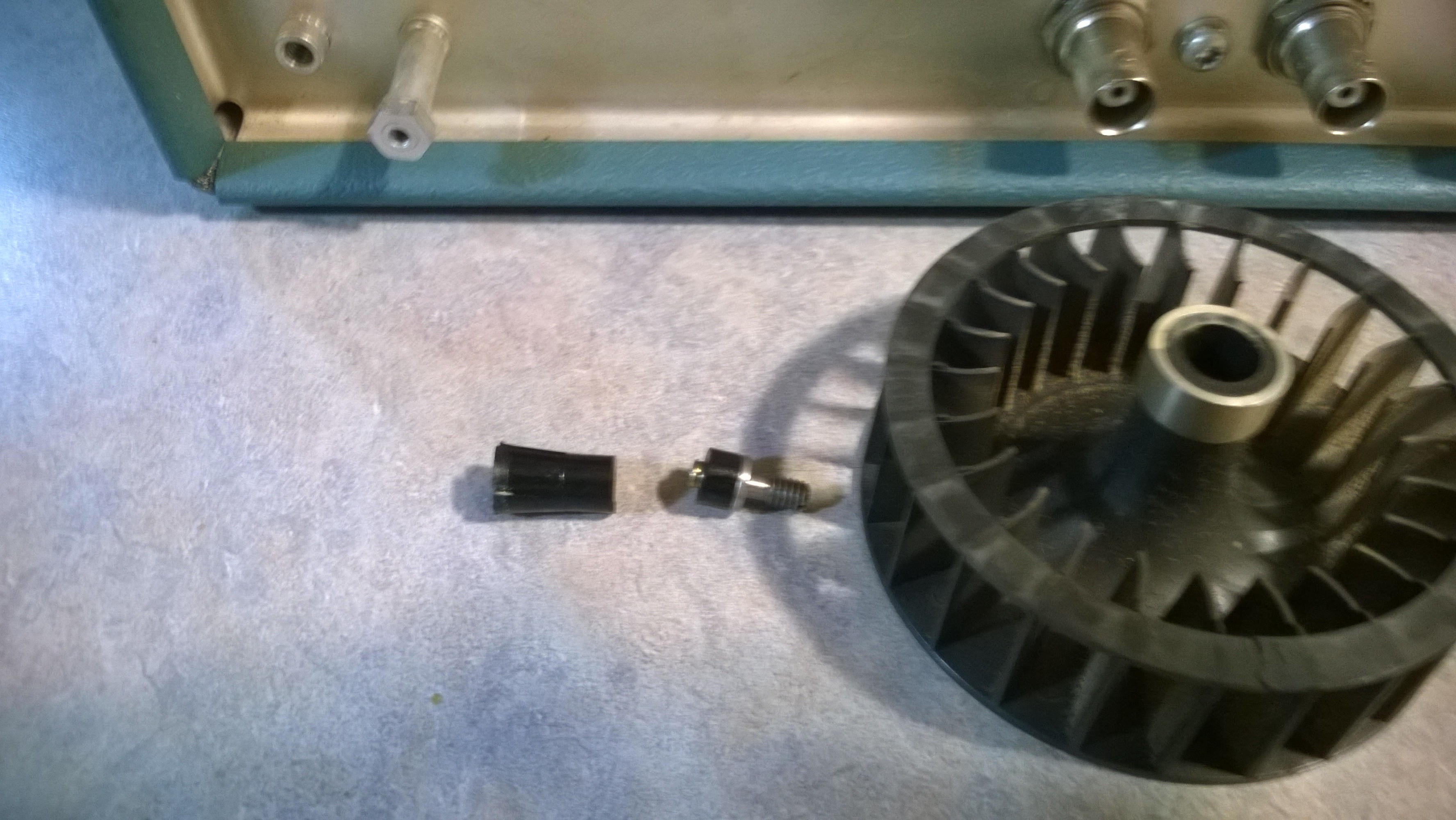
Here's an example of the inner collet snapping in half when attempting to pull the fan off the shaft. It's no big deal. Either epoxy or cyanoacrylate (super glue) will fix it right up.


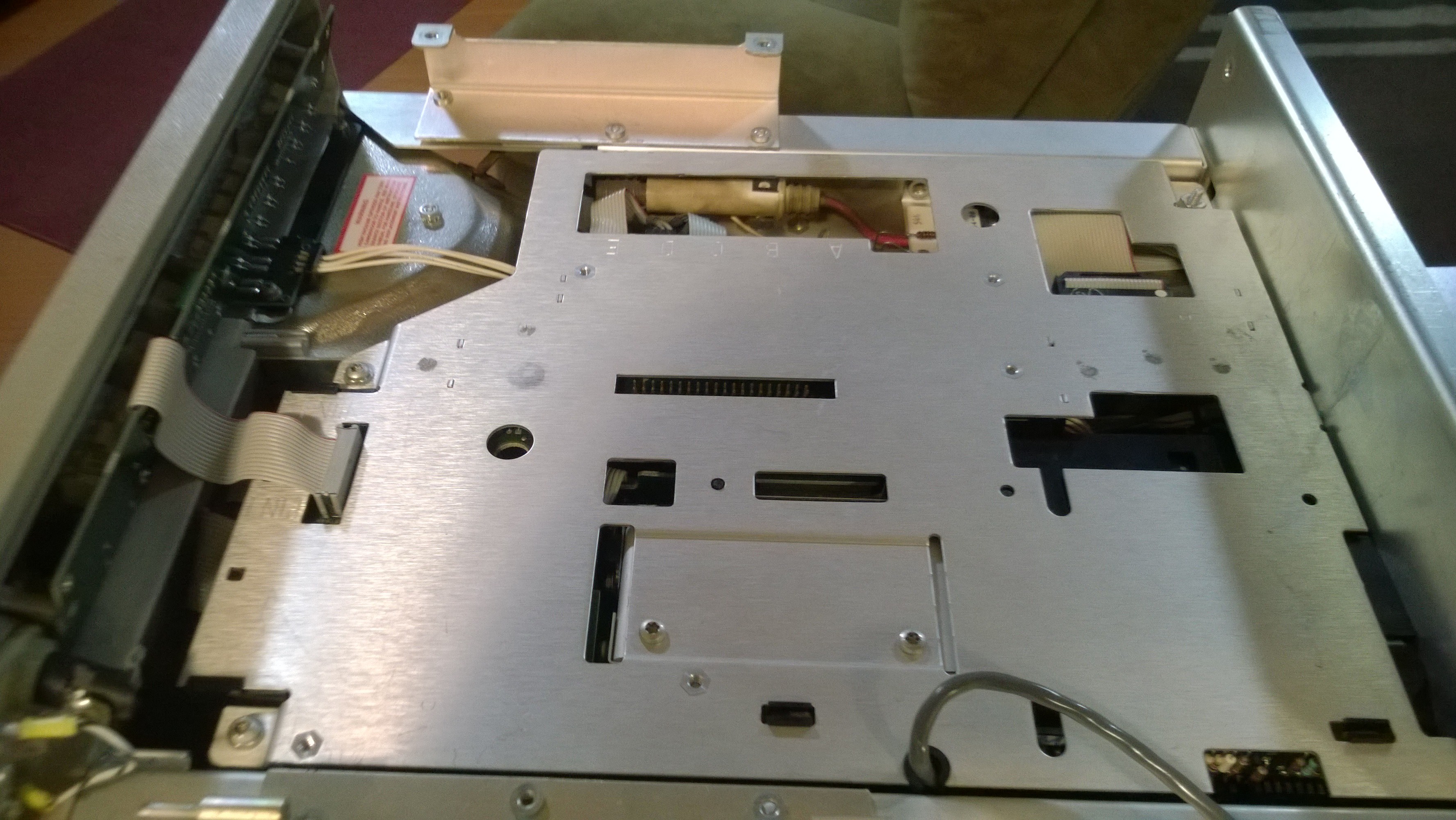
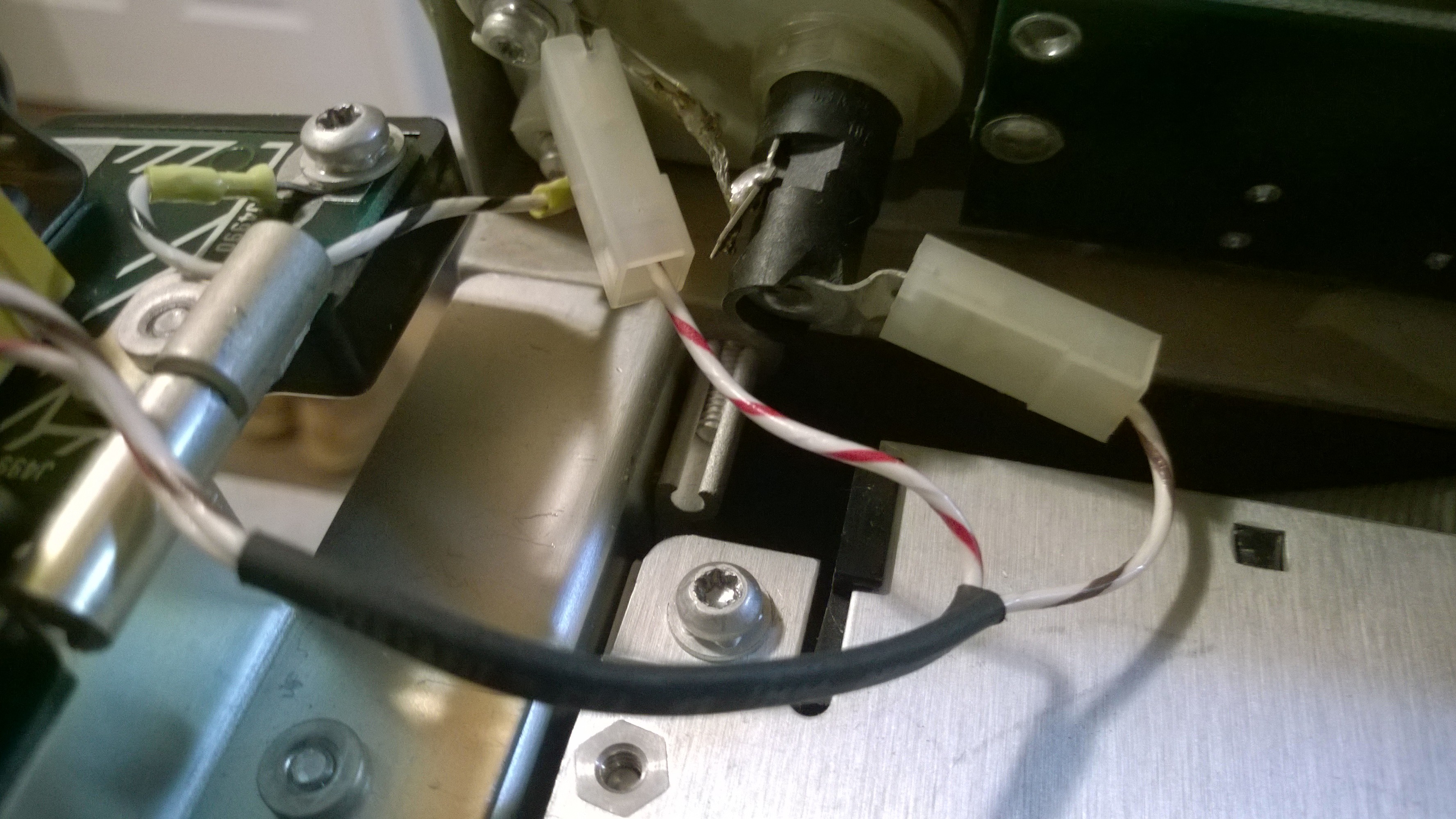
The DMM Board must be completely removed. Remove the 2 screws on the left side.


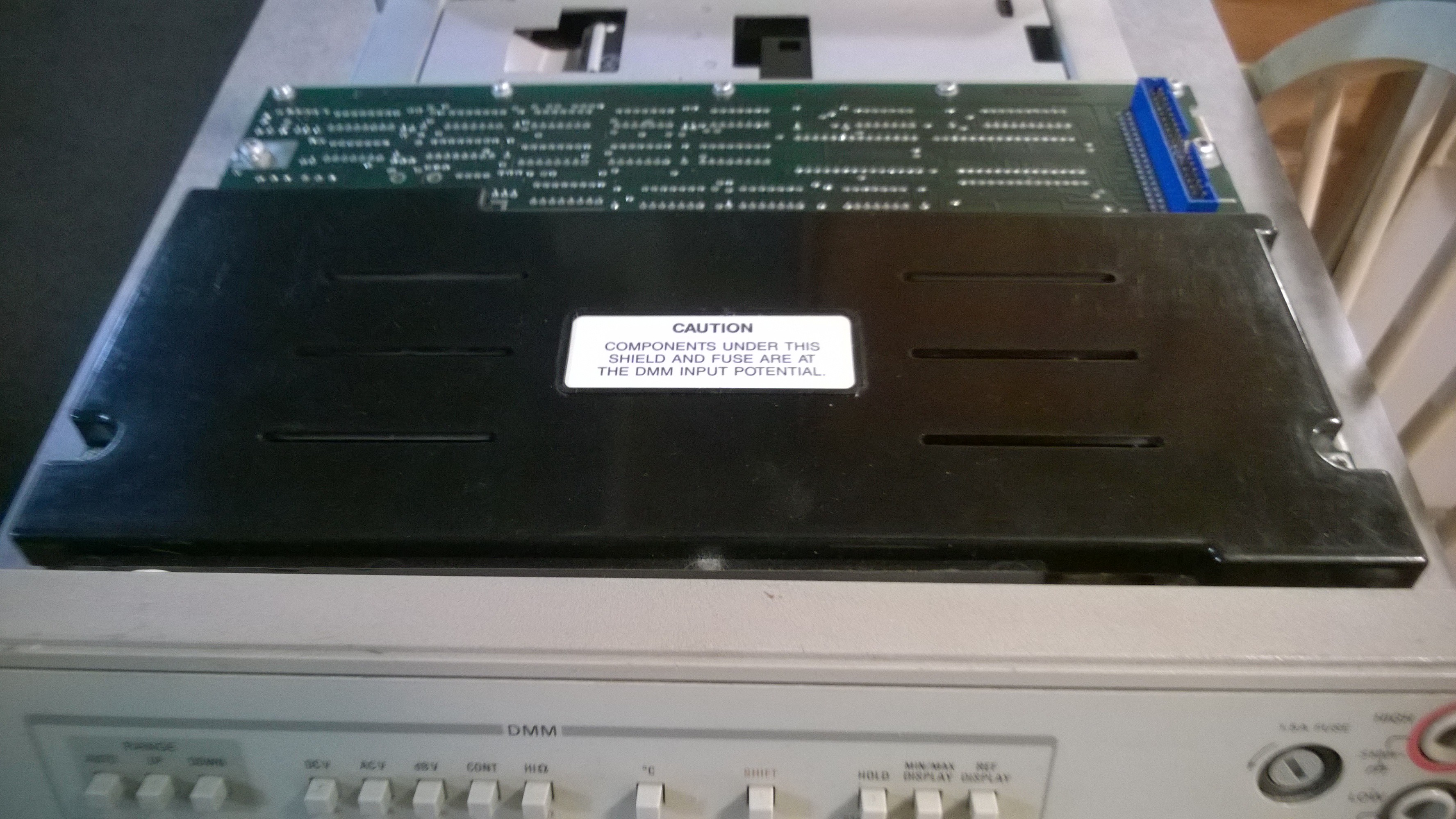
Now swing the board completely to the right. The white cable is to the beeper on the front panel that will unplug as you swing the board over.


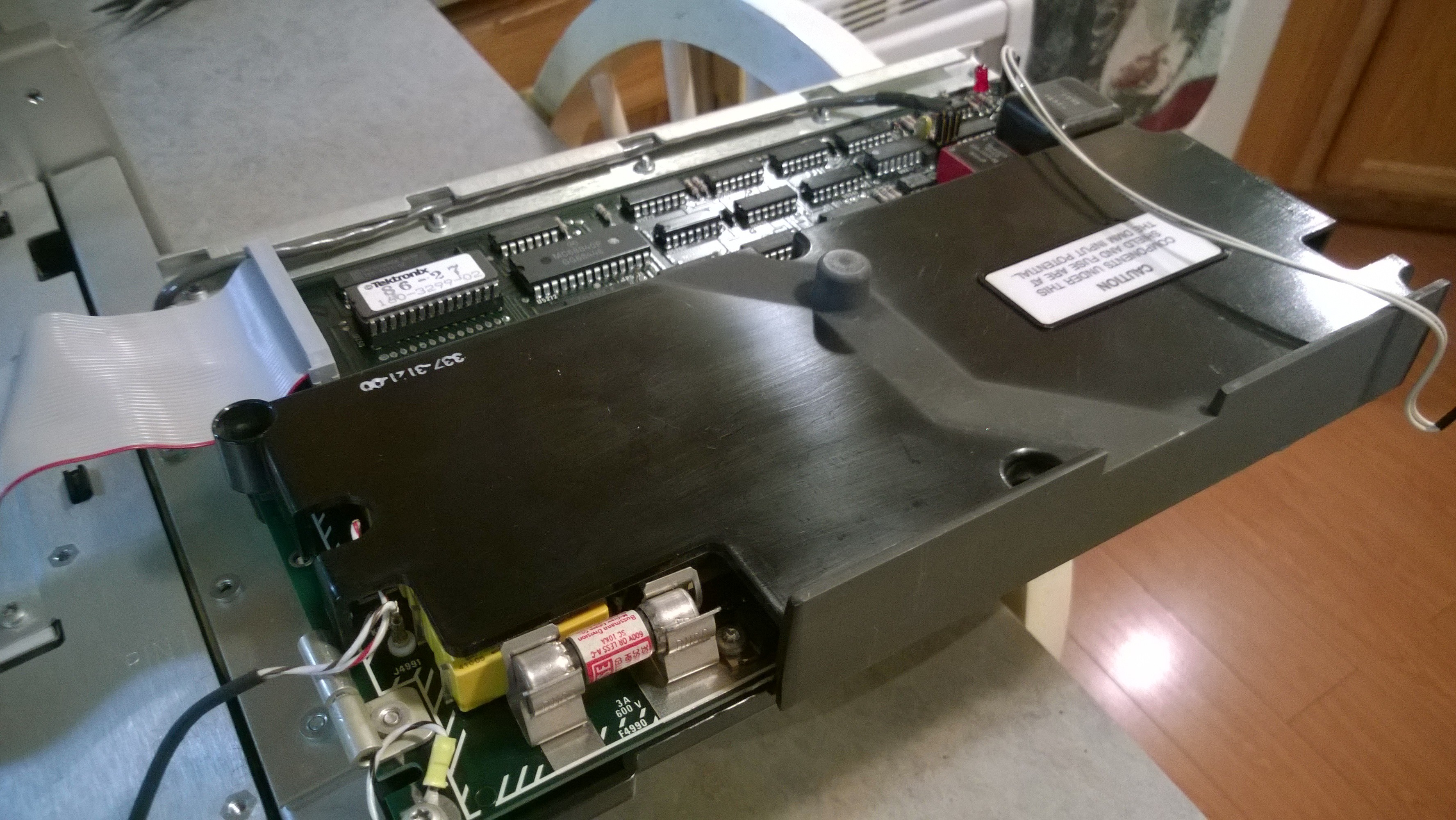
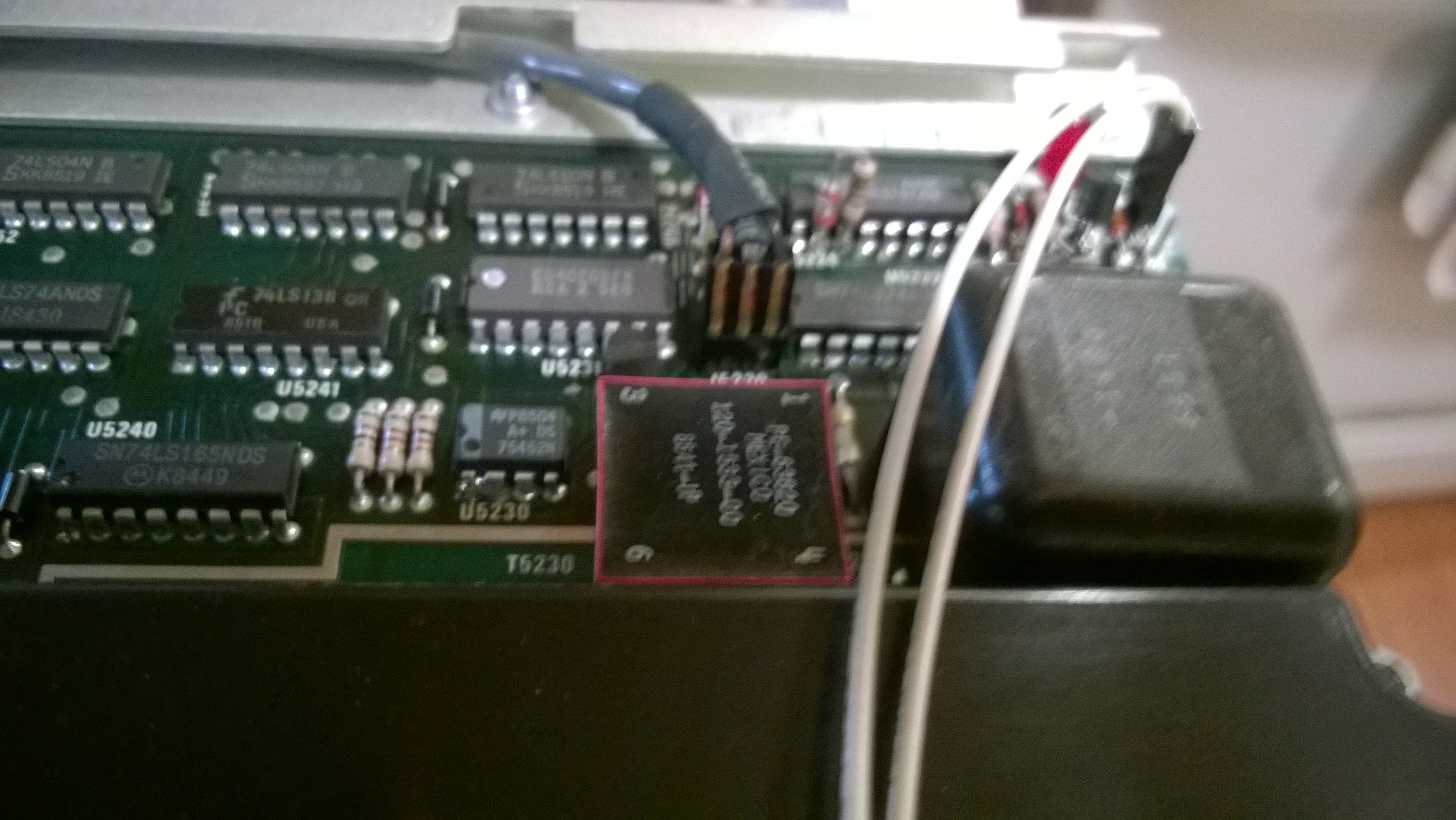
Pull the connector on the far right.


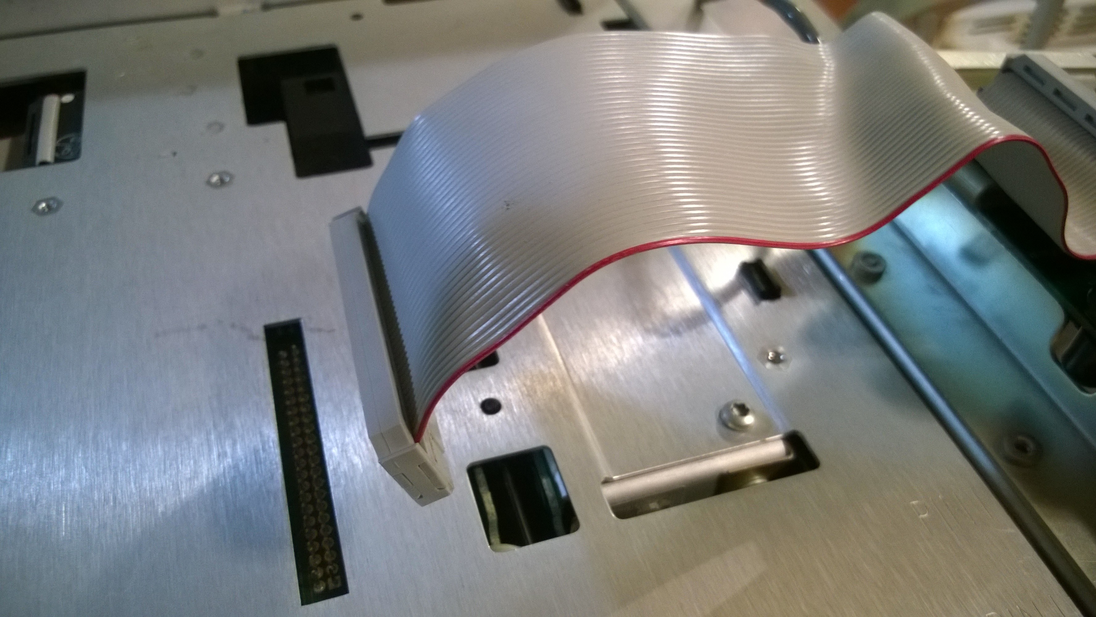
Remove ribbon cable from top plate.


Pull connectors off front banana jacks. Unbolt ground wire from board. Now the DMM Board can be removed.


The top plate is now accessible. Looks innocent enough, doesn't it? The real fun is yet to begin in Part 2.

« Last Edit: October 01, 2018, 04:07:23 am by med6753 »
An old gray beard with an attitude.
 
The following users thanked this post: BravoV, cheeseit, worsthorse

Online xrunner

  • Super Contributor
  • ***
  • Posts: 7517
  • Country: us
  • hp>Agilent>Keysight>???
Re: Tektronix 2465B oscilloscope teardown
« Reply #1171 on: October 01, 2018, 02:18:26 am »

The top plate is now accessible. Looks innocent enough, doesn't it? The real fun is yet to begin in Part 2.


Something scary must be underneath there. I can't wait.  :popcorn:
I told my friends I could teach them to be funny, but they all just laughed at me.
 

Offline med6753

  • Super Contributor
  • ***
  • Posts: 11313
  • Country: us
  • Tek nut
Re: Tektronix 2465B oscilloscope teardown
« Reply #1172 on: October 01, 2018, 03:43:47 am »
Part 2. Top plate removal. Remove all the fasteners around the perimeter of the top plate. There are 2 additional fasteners that secure the plate to the PSU underneath.


Carefully and slowly start pulling straight up on the plate. It will be tight because there are 2 large pin connectors that interface to the PSU underneath. But don't pull too far yet. Maximum of about 2 inches.


On the A5 board side remove these 2 connectors from the top plate.


On the front pull the ribbon cable.


Underneath that ribbon cable are 2 additional ribbon cables that need to be removed. VERY IMPORTANT. Note how they are oriented with red stripe to the left. And don't mix them up. Ask me how I know this? No....don't ask.


On the left side by the CRT remove these 3 connectors.


Same side in the rear remove the GPIB interface cable.


In the rear, down that rabbit hole that the camera didn't pick up are the connectors for probe power, if that feature is installed.


Now start pulling straight up. On the left side by the CRT there will be an additional connector to the Counter/Trigger board.


Now the top plate can be removed. And this is what you have. Attached to the plate itself is the Buffer Board. Plugged into that is the Counter/Trigger Board and behind it the GPIB board. You are probably thinking “that wasn't too bad”. Just wait, putting it all back together is the fun part.


So now the PSU is exposed and can be removed. I STRONGLY recommend if a re-cap hasn't been done do it now. Reference here for details:

https://www.eevblog.com/forum/testgear/tektronix-2465b-oscilloscope-teardown/msg1658219/#msg1658219


Part 3 will deal with the fan motor and then the reassembly.

An old gray beard with an attitude.
 
The following users thanked this post: BravoV, cheeseit

Offline med6753

  • Super Contributor
  • ***
  • Posts: 11313
  • Country: us
  • Tek nut
Re: Tektronix 2465B oscilloscope teardown
« Reply #1173 on: October 01, 2018, 06:18:07 am »
Part 3 will deal with the fan motor and then the tedious task of reassembly.

Here's the PSU on the bench. The fan motor is behind that black assembly on the right.


Once free unplug the connector..


Unsolder it from the circuit board.


The method I chose to use for repair was the one proposed by user Siggi in this post:

https://www.eevblog.com/forum/testgear/tektronix-2465b-oscilloscope-teardown/msg1715741/#msg1715741

But my motor had an unexpected surprise. There was no retaining screw. Just a hole over the rear bushing. And a small amount of a black substance which appeared to be ground up bushing. The area was greasy and gummy, including the spacer. It appears that someone has been in here before but I'm not sure. But I decided to forge ahead with a repair anyway. (Don't have any pictures. Seems my phone “ate” them...sorry) I cleaned everything with 100% IPA. Once dry I used a Q-tip soaked in synthetic motor oil and forced it into the hole. (I suppose light machine oil would be a better choice and I don't have any). I then set the motor in the vertical position with the rear bushing up overnight to insure the oil soaked in. Then another cleaning on the exterior with IPA. Resoldered to the circuit board then reinstalled into the PSU.

Here's it reinstalled into the PSU.


And the PSU reinstalled into the scope.   


Reassembly of the Top Plate: No pictures since it's basically a reversal of the disassembly. But some things to be aware of. First, if you re-capped the PSU it is imperative that you reassembled it correctly. If it isn't you'll never get the PSU and Top Plate to align properly. Second, there isn't a lot of slack in some of the cables and trying to get everything connected while having the room to get your fingers where needed can be extremely frustrating. Work slow and carefully. Once all the cabling is done insure the plate is aligned with the pin connectors to the PSU and carefully push it down into place. If done correctly all the perimeter screw holes will align. If they don't something is wrong and you need to find the cause.

Once you're confident the plate is properly aligned install the fasteners. Then reinstall the DMM board and the cage fan. Then you are ready for the smoke test. Hopefully there isn't any.

What were my results? The fan motor for the first time since I've owned this scope is totally silent. So far the repair has worked and I've run it several hours. Will it last? Hard to say. I think this motor is potentially on it's last legs. But so far it's a thumbs up.  :-+
« Last Edit: October 01, 2018, 04:03:08 pm by med6753 »
An old gray beard with an attitude.
 
The following users thanked this post: BravoV, cheeseit

Offline BravoVTopic starter

  • Super Contributor
  • ***
  • Posts: 7547
  • Country: 00
  • +++ ATH1
Re: Tektronix 2465B oscilloscope teardown
« Reply #1174 on: October 01, 2018, 06:43:36 am »
med6753, gorgeous machine  :clap: and thanks for sharing the nicely shot detail photos.  :-+

Is there any reason you don't use the forum's attachment instead of hosting them at imageshack ?

Really worry if someday imageshack acting up, all of this great photos with details will be lost, as we already have few valuable post that had photos gone at earlier posts in this thread alone.  :'(


Share me

Digg  Facebook  SlashDot  Delicious  Technorati  Twitter  Google  Yahoo
Smf