Author Topic: Nanovolt scanner card teardown, Keithley 7168 and it's use for resistor logging  (Read 15746 times)

0 Members and 2 Guests are viewing this topic.

Offline TiNTopic starter

  • Super Contributor
  • ***
  • Posts: 4543
  • Country: ua
    • xDevs.com
I bet only true volt-nut know what is this one:


Prize for correct guess for manufacturer & model number : first to see full set of pics  :-DMM
« Last Edit: February 14, 2017, 04:24:07 am by TiN »
YouTube | Metrology IRC Chat room | Let's share T&M documentation? Upload! No upload limits for firmwares, photos, files.
 

Offline CatalinaWOW

  • Super Contributor
  • ***
  • Posts: 5252
  • Country: us
Re: Volt-nut test for EEVBlog readers
« Reply #1 on: January 21, 2017, 04:46:22 pm »
I don't know what it is, but I always get nervous when I see a situation like the read wire leading to the terminal marked "HIGH"
 

Offline Echo88

  • Frequent Contributor
  • **
  • Posts: 826
  • Country: de
Re: Volt-nut test for EEVBlog readers
« Reply #2 on: January 21, 2017, 05:49:01 pm »
:o Keithley 7168 Nanovolt Card?!  :scared:
 

Offline Vgkid

  • Super Contributor
  • ***
  • Posts: 2710
  • Country: us
Re: Volt-nut test for EEVBlog readers
« Reply #3 on: January 21, 2017, 06:45:23 pm »
Datron 4910?
If you own any North Hills Electronics gear, message me. L&N Fan
 

Offline CalMachine

  • Frequent Contributor
  • **
  • Posts: 477
  • Country: us
  • Metrology Nut
Re: Volt-nut test for EEVBlog readers
« Reply #4 on: January 21, 2017, 11:22:04 pm »
A Dataproof 160 or 320 scanner unit?
All your volts are belong to me
 

Offline Pipelie

  • Regular Contributor
  • *
  • Posts: 172
  • Country: cn
Re: Volt-nut test for EEVBlog readers
« Reply #5 on: January 22, 2017, 01:37:44 am »
Keithley 7168 Nanovolt Scanner Card
 

Offline Pipelie

  • Regular Contributor
  • *
  • Posts: 172
  • Country: cn
Re: Volt-nut test for EEVBlog readers
« Reply #6 on: January 22, 2017, 01:52:21 am »
here is the manual for 7168
http://www.cedesa.com.mx/pdf/keithley/keithley_7168_user_manual.pdf

1.TiN is a fan of keithley, and look at the layout, i bet it is come from keithley
2. Copper Spade Lug, more than 3 channel , should be scanner card relate to Low Thermal EMF
3. most important is the manual of 7168 have a component location drawing.
 

Offline TiNTopic starter

  • Super Contributor
  • ***
  • Posts: 4543
  • Country: ua
    • xDevs.com
Re: Volt-nut test for EEVBlog readers
« Reply #7 on: January 22, 2017, 06:27:46 am »
Yes, it is indeed KI 7168. This card originally designed for 705 scanner, but supported by newer 7001/7002 too.
My 7001 is torn apart for parts, so I will use little DIY solution and RPI to control the card. It have optocoupler inputs and simple to control.
Interesting to see, it has two 15V batteries (white cylinders in corner) to provide isolated power. Still measured ok.


Spade lugs are soldered to wires/inductor legs in sloppy way.


Bottom side of JFETs are covered by plastic cap with gasket. Pins also covered in thermal grease. I wonder why top side with JFETs not enclosed similar way?


JFETs marking is J2771. Anyone know the part number or have datasheet?
YouTube | Metrology IRC Chat room | Let's share T&M documentation? Upload! No upload limits for firmwares, photos, files.
 
The following users thanked this post: doktor pyta, CalMachine, eplpwr

Offline Vgkid

  • Super Contributor
  • ***
  • Posts: 2710
  • Country: us
Re: Teardown of nanovolt scanner card, Keithley 7168
« Reply #8 on: January 22, 2017, 08:38:58 am »
That is rather strange about the cap being on the underside of the jfets, rather than all around it. From the manual, I can infer that that they are trying to allow them to equalize(to temperature) as quickly as possible. Still, I would have done something about the solder joints on the surface of the PCB.
If you own any North Hills Electronics gear, message me. L&N Fan
 

Offline Kleinstein

  • Super Contributor
  • ***
  • Posts: 14256
  • Country: de
Re: Teardown of nanovolt scanner card, Keithley 7168
« Reply #9 on: January 22, 2017, 09:46:52 am »
The top side has the metal cover for the whole circuit. There are not many heat sources there - so rather low temperature gradients.


It is a low volume product, so not every thing might be thought to the end - sometimes good enough is all it needs.
What is a little strange to me, it that the opto-couplers are relatively close, and no thermal insulation there.
 

Offline quarks

  • Frequent Contributor
  • **
  • Posts: 874
  • Country: de
Re: Teardown of nanovolt scanner card, Keithley 7168
« Reply #10 on: January 22, 2017, 11:00:25 am »
Bookmark
 

Offline EmmanuelFaure

  • Regular Contributor
  • *
  • Posts: 154
  • Country: 00
Re: Teardown of nanovolt scanner card, Keithley 7168
« Reply #11 on: January 22, 2017, 04:20:58 pm »
@ TiN : Could you upload/provide a link for high resolution pictures? Thanks you :)
 

Offline Vtile

  • Super Contributor
  • ***
  • Posts: 1144
  • Country: fi
  • Ingineer
Re: Teardown of nanovolt scanner card, Keithley 7168
« Reply #12 on: January 23, 2017, 12:14:28 am »
Maybe the heat paste is there if the ends of the legs are the place that creates thermoelectric effect with solder and copper or solder & legmaterial, if there is temp difference between legs?  Newb quessing.

Interesting anyway.
« Last Edit: January 23, 2017, 12:15:59 am by Vtile »
 

Offline TiNTopic starter

  • Super Contributor
  • ***
  • Posts: 4543
  • Country: ua
    • xDevs.com
Re: Teardown of nanovolt scanner card, Keithley 7168
« Reply #13 on: January 23, 2017, 04:06:08 am »
@ TiN : Could you upload/provide a link for high resolution pictures? Thanks you :)

There will be article on my site about it later this week. If you desperate, file-naming rules for any of my pics didn't change ;).
YouTube | Metrology IRC Chat room | Let's share T&M documentation? Upload! No upload limits for firmwares, photos, files.
 

Offline EmmanuelFaure

  • Regular Contributor
  • *
  • Posts: 154
  • Country: 00
Re: Teardown of nanovolt scanner card, Keithley 7168
« Reply #14 on: January 23, 2017, 07:19:46 pm »
If you desperate, file-naming rules for any of my pics didn't change ;).

Found them! I should have started by checking that. Thanks :)
 

Offline Kleinstein

  • Super Contributor
  • ***
  • Posts: 14256
  • Country: de
Re: Teardown of nanovolt scanner card, Keithley 7168
« Reply #15 on: January 23, 2017, 07:53:05 pm »
Normally there should be very little heat sources in the scanner part: the main part is more like gate leakage time control voltage. So more like the low nW range. So with the metal cover there should be very low temperature gradients over most of the board.

It is only the opto-couplers that could could have a significant power (maybe in the 10 mW range from active LEDs).

So I really don't understand those covers and the white paste on the back.
 

Offline Assafl

  • Frequent Contributor
  • **
  • Posts: 600
Re: Teardown of nanovolt scanner card, Keithley 7168
« Reply #16 on: January 31, 2017, 09:44:51 am »
Normally there should be very little heat sources in the scanner part: the main part is more like gate leakage time control voltage. So more like the low nW range. So with the metal cover there should be very low temperature gradients over most of the board.

It is only the opto-couplers that could could have a significant power (maybe in the 10 mW range from active LEDs).

So I really don't understand those covers and the white paste on the back.

They state in the manual (section 2.6.6 - switching FET thermals) that the FETs normally will have negligible dissipated heat (they give an example of a 1GOhm input voltmeter reading 200mV so the power dissipated is in the order of 10^-19W).

However, they also add that at the maximum current through the FET being 50mA the dissipated heat would be 25mW. They add that at this level of power dissipation substantial thermal voltages can be generated by FET heating. Furthermore, they recommend that one wait for an hour after switching currents larger than 1mA for temperatures to stabilize before measuring.

My guess is therefore that the cover and paste are for ensuring that the FET solder joints are all at near thermal equilibrium (even if one of the pins would normally be marginally warmer as it for example, forms the pad for the die).     
 

Offline TiNTopic starter

  • Super Contributor
  • ***
  • Posts: 4543
  • Country: ua
    • xDevs.com
Re: Teardown of nanovolt scanner card, Keithley 7168
« Reply #17 on: January 31, 2017, 11:36:55 am »
Having cover on top with grease would help this purpose much better though.
YouTube | Metrology IRC Chat room | Let's share T&M documentation? Upload! No upload limits for firmwares, photos, files.
 

Offline Squantor

  • Contributor
  • Posts: 41
  • Country: nl
Re: Teardown of nanovolt scanner card, Keithley 7168
« Reply #18 on: February 01, 2017, 08:12:13 am »
Having cover on top with grease would help this purpose much better though.

I am not so sure, what I can rememeber from my time at NXP is that the gate electrode in JFETs is the substrate. In the TO-92 package the substrate pin is usually the middle pin, maybe by coupling those with thermal grease you get a better coupling instead of putting a cap over the TO-92 bodies and bind them with thermal grease. This is all theory and could be tested.
 

Offline TiNTopic starter

  • Super Contributor
  • ***
  • Posts: 4543
  • Country: ua
    • xDevs.com
Re: Teardown of nanovolt scanner card, Keithley 7168
« Reply #19 on: February 01, 2017, 02:18:33 pm »
"Just add level shift".

I don't have supposed scanner to use 7168 as is, but I do have Keithley 7001 skeleton (with parts/VFD removed for donor in 2001). Well, that will do just fine. All I need is to put Raspberry Pi inside, add a level shift breadboard to drive backplane UCN5841's which interface 7168 scanner card, and write some code :) Onboard switching PSU have handy +6V and +14.6V, so it's easy to downconvert for +5V to power Pi.


Will use 16x2 OLED instead of front panel, to show which channel currently used/status/LAN IP.

Bottom compartment can be also used to store few LTZ-based references maybe.  >:D
YouTube | Metrology IRC Chat room | Let's share T&M documentation? Upload! No upload limits for firmwares, photos, files.
 
The following users thanked this post: dr.diesel

Offline TheSteve

  • Supporter
  • ****
  • Posts: 3755
  • Country: ca
  • Living the Dream
Re: Teardown of nanovolt scanner card, Keithley 7168
« Reply #20 on: February 01, 2017, 05:12:33 pm »
Your pi looks to be short a processor.
VE7FM
 
The following users thanked this post: dr.diesel

Offline dr.diesel

  • Super Contributor
  • ***
  • Posts: 2214
  • Country: us
  • Cramming the magic smoke back in...
Re: Teardown of nanovolt scanner card, Keithley 7168
« Reply #21 on: February 01, 2017, 05:15:45 pm »
Your pi looks to be short a processor.

 :-DD  I didn't even notice!  Gotta be a good story there.

Offline TiNTopic starter

  • Super Contributor
  • ***
  • Posts: 4543
  • Country: ua
    • xDevs.com
Re: Teardown of nanovolt scanner card, Keithley 7168
« Reply #22 on: February 03, 2017, 04:52:05 am »
Oh, i was guessing what was that  hot part on Pi. Moral of the story was don't be lazy and always add buffering on SOC GPIO pins.

I've got Pi running, powered from K7001 PSU. Test dummy socket server-client app also got up to allow control over LAN.

Little bodge with 4 NFETs added to SPI port to act as 3.3V -> 5V level translator. I'll connect it to native 7001 backplane board to control 5814 SRs. With some simple coding should be easy to get going.
YouTube | Metrology IRC Chat room | Let's share T&M documentation? Upload! No upload limits for firmwares, photos, files.
 

Offline TiNTopic starter

  • Super Contributor
  • ***
  • Posts: 4543
  • Country: ua
    • xDevs.com
Re: Teardown of nanovolt scanner card, Keithley 7168
« Reply #23 on: February 04, 2017, 07:15:35 pm »
Alright, we getting there. Just bit of spaghetti-coding, and should be ready for first run tomorrow.
Suggestions what to test first are welcome!

Today's photos... Just first checks on level translator bodge and testing code to control 7001 backplane serial drivers (UCN5841, latched 8bit driver).


One hour and channels are working fine..

Channel ON:


Channel OFF:


Wiring and rear Pi location:


Looks ugly, but should be good enough. I decided to deviate from my usual "design custom PCB, do weeks and weeks of testing" and just bodged one off thing which seem to work. Don't want this to turn into month-long project.


I don't have original 7001 front panel anymore (well, I have the board, but it has no VFD), so plonked 16x2 OLED instead to show status/IP/etc.


 ;D
YouTube | Metrology IRC Chat room | Let's share T&M documentation? Upload! No upload limits for firmwares, photos, files.
 
The following users thanked this post: dr.diesel

Offline ManateeMafia

  • Frequent Contributor
  • **
  • Posts: 731
  • Country: us
Re: Teardown of nanovolt scanner card, Keithley 7168
« Reply #24 on: February 04, 2017, 07:31:18 pm »
How about measuring thermal offsets and leakage current of all the switches?


Offline lukier

  • Supporter
  • ****
  • Posts: 634
  • Country: pl
    • Homepage
Re: Teardown of nanovolt scanner card, Keithley 7168
« Reply #25 on: February 04, 2017, 08:10:58 pm »
Today's photos...

Hmm that's not CSA7404  :D. Is there an exciting repair story associated with this new Tek? :)
 

Offline TiNTopic starter

  • Super Contributor
  • ***
  • Posts: 4543
  • Country: ua
    • xDevs.com
Re: Teardown of nanovolt scanner card, Keithley 7168
« Reply #26 on: February 04, 2017, 08:34:21 pm »
Nope, it's boring brand new. Borrowed for some other tests.
YouTube | Metrology IRC Chat room | Let's share T&M documentation? Upload! No upload limits for firmwares, photos, files.
 

Offline TiNTopic starter

  • Super Contributor
  • ***
  • Posts: 4543
  • Country: ua
    • xDevs.com
Re: Teardown of nanovolt scanner card, Keithley 7168
« Reply #27 on: February 07, 2017, 04:22:04 am »
First data bodges came in! :)
8K samples using K7168 card, A10 (A=100K) and K2002.

nvs1.png is data as is, 1000 samples per channel.
nvs1_ofs.png is same dataset, but with offsets removed via math.

Copper short is directly on card channels terminals. Card was NOT cleaned/serviced. So that's next step, clean all copper surfaces, make fresh shorts, and retest again.  ;)
Channels 5,6,7,8 already look decent even with condition as is.
YouTube | Metrology IRC Chat room | Let's share T&M documentation? Upload! No upload limits for firmwares, photos, files.
 

Offline TiNTopic starter

  • Super Contributor
  • ***
  • Posts: 4543
  • Country: ua
    • xDevs.com
Re: Teardown of nanovolt scanner card, Keithley 7168
« Reply #28 on: February 14, 2017, 04:23:15 am »
First usage case of Keithley 7168 just about to get proof. As some followers might discover, I recently snagged nice stash of 60+ pcs Vishay BMF resistors, all of which would be cool to test for tempco.
If I'd do that using two 8.5-digit meters and nV-meter+current source, that will take..

30 hours for one run, 3 resistors at at time (2002+2002+182M) = 20 runs * 30 hours/each = 600 hours + setup time. That's 25+ days of testing.  :o
111 hours for one run, 10 resistors at a time (2002+2002+182M+7168) = 6 runs * 111 hours/each = 666 hours + setup time. 27 days of testing  :rant: :scared:

Perhaps I could optimize delays/settings a bit to run scanner setup bit quicker.

Setup for regular DMMs is simple: Keithley 2002 U1 measures 1 x VPG102L 40.000 K? #2 BMFR, 200K range, OCOMP OFF, Keithley 2002 U2 measures 1 x VPG102L 40.000 K? #1 BMFR, 200K range, OCOMP OFF, same.

Resistor test using scanner is bit different, using 
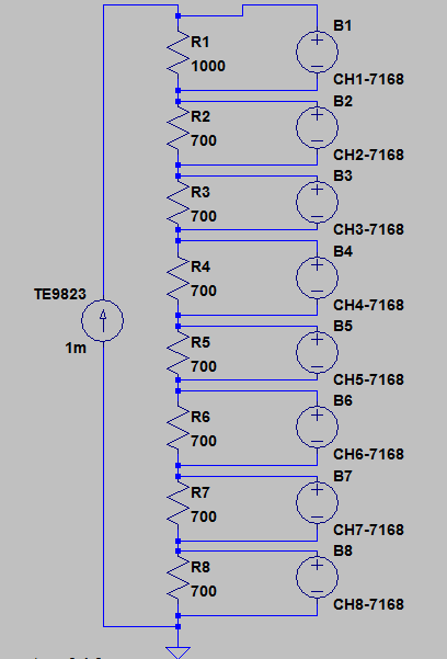
Time Electronics 9823 MFC to source stable 1.00000 mADC (confirmed by 3458A) to chain of 8 resistors (AE 1K? + S102 700? + S102 700? + S102 700? + S102 700? + S102 700? + S102 700? + S102 700?). 
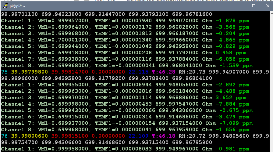
Keithley 7168 8-channel nanovolt scanner + RPI in K7001 chassis scanning voltage across each resistor in chain, using Kelvin connection. Resistors are tied to copper foil to keep their temperature gradients equal. After each reading with current Keithley 182-M measures voltage across resistor, then MFC source 0.00000 mADC current and voltmeter reads TEMF compensation voltage to calculate offset compensated OHM. Formula for resulting R simply equal V_curr_on - V_curr_off / 1E-3 mA.

Then resulting DSV-log uploaded to my server, from which on special page my ugly D3.js Javascript contraption cooks rainbow-monster graph. Deviation shown in ppm/reference, with reference values for each channel used as:

Code: [Select]
var ref_ch1    = 999.951202;           // 7168 CH1
var ref_ch2    = 699.960845;           // 7168 CH2
var ref_ch3    = 699.966292;           // 7168 CH3
var ref_ch4    = 699.997901;           // 7168 CH4
var ref_ch5    = 699.941758;           // 7168 CH5
var ref_ch6    = 699.913797;           // 7168 CH6
var ref_ch7    = 699.938197;           // 7168 CH7
var ref_ch8    = 699.968415;           // 7168 CH8
var ref_k4     = 39998.171;            // 2002 4
var ref_k6     = 39998.007;            // 2002 6

These are spot readings after 3 hours of 20.00C stable temperature in box. These are our "zero" points from which we calculate tempco.


Initial chart:


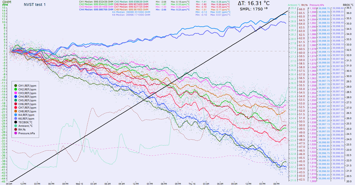
Script calculates min/max tempco for each channel as ppm / max temperature from 20C baseline. JS data on page is updated in realtime as data capture goes
Come back after 111 hours :)

« Last Edit: February 14, 2017, 04:40:57 am by TiN »
YouTube | Metrology IRC Chat room | Let's share T&M documentation? Upload! No upload limits for firmwares, photos, files.
 

Offline TiNTopic starter

  • Super Contributor
  • ***
  • Posts: 4543
  • Country: ua
    • xDevs.com
Slowly but surely data is coming thru. As one can see, all seven 700 Ohm S102 + 1K AE are linearly going down, having linear tempco around -1.2...-2.8ppm/K.
Pair of 40K hermetical VHP102L going little up (these two measured by direct 4W connection at own K2002's).


What i'm happy to see is no random non-linear stuff, so setup seem to be working as expected. I have few ideas try speed up next test from 110 hours to ~35 hours.
Right now current source is applied on each resistor on scanner card individually. Meaning it takes a lot of time, as there are 8 seconds to let current source and scanner switch to settle. Double that time, as two measurements taken to remove thermal EMF (one with 1mA current, second with 0mA current).

By moving current source control outside of switching cycles and doing 8 measurements with current source on, and then again 8 measurements with current source off might work as well, as it would be <10 seconds between compensation cycles and unlikely that thermal EMF change a lot in this time. I also will modify method a bit, to source +1mA and reversal -1mA instead of +1mA and zero current. Similar is done in TruOhm mode on Datron 1271/1281/8508A.

YouTube | Metrology IRC Chat room | Let's share T&M documentation? Upload! No upload limits for firmwares, photos, files.
 

Offline mimmus78

  • Supporter
  • ****
  • Posts: 676
  • Country: it
Hi guys,

I'd like to try to create a clone of this card for my lab. I was searching the most appropriate jfet for the purpose so I come to two possible options:

1. IFN5432
2. MMBF5434

The first is hard to find and costs a lot.
The second have an SMD package, a reasonable price and is easy to find.
I think SMD package can also help a little to control EMF.
Cons is that it have higher ON resistance.

Both JFET have higher Ron resistance and leakage than Keithley 7168 specification ... does anyone know better options for the purpose? 

Regards,

D.
 

Offline Echo88

  • Frequent Contributor
  • **
  • Posts: 826
  • Country: de
I never could find a datasheet for the JFETs used in the K7168 and only know that they have copper pins. Would have to calculate the errors, but i dont think that leakage plays a role here/can be omitted by a suitable changed schematic?

If its just about RDSon i also can name the J105: http://pdf.datasheetcatalog.com/datasheet/vishay/70230.pdf

At the moment im building my voltage-reference-scanner based on PVA1054-OptoFETs (35R RDSon, 10GR Off-resistance, they also have copper-pins). According to my calculations the 35R and leakage dont matter when a 10G-input-DMM is used. Also my first tests with a Keithley 181 Nanovoltmeter showed <= 30nV error with these OptoFETs which is absolutely sufficient to me. I will post results when i finished building the scanner.
 
The following users thanked this post: mimmus78

Offline Kleinstein

  • Super Contributor
  • ***
  • Posts: 14256
  • Country: de
My guess is that leakage could be more of a problem than a slightly higher R_on. Also FETs that are good for 25 V might limit the useful range, as you still have to subtract the control voltage from that.

I would more consider something like J111 / MMBFJ111.
 
The following users thanked this post: mimmus78

Offline mimmus78

  • Supporter
  • ****
  • Posts: 676
  • Country: it
I never could find a datasheet for the JFETs used in the K7168 and only know that they have copper pins. Would have to calculate the errors, but i dont think that leakage plays a role here/can be omitted by a suitable changed schematic?

If its just about RDSon i also can name the J105: http://pdf.datasheetcatalog.com/datasheet/vishay/70230.pdf

At the moment im building my voltage-reference-scanner based on PVA1054-OptoFETs (35R RDSon, 10GR Off-resistance, they also have copper-pins). According to my calculations the 35R and leakage dont matter when a 10G-input-DMM is used. Also my first tests with a Keithley 181 Nanovoltmeter showed <= 30nV error with these OptoFETs which is absolutely sufficient to me. I will post results when i finished building the scanner.
30nV seems pretty good also to me ... Considering there is a led inside the thingy that will heat up the chip is even more exceptional.

Inviato dal mio ONEPLUS A5010 utilizzando Tapatalk
 

Offline mimmus78

  • Supporter
  • ****
  • Posts: 676
  • Country: it
I never could find a datasheet for the JFETs used in the K7168 and only know that they have copper pins. Would have to calculate the errors, but i dont think that leakage plays a role here/can be omitted by a suitable changed schematic?

If its just about RDSon i also can name the J105: http://pdf.datasheetcatalog.com/datasheet/vishay/70230.pdf

At the moment im building my voltage-reference-scanner based on PVA1054-OptoFETs (35R RDSon, 10GR Off-resistance, they also have copper-pins). According to my calculations the 35R and leakage dont matter when a 10G-input-DMM is used. Also my first tests with a Keithley 181 Nanovoltmeter showed <= 30nV error with these OptoFETs which is absolutely sufficient to me. I will post results when i finished building the scanner.
How do you know there are copper pin?

Inviato dal mio ONEPLUS A5010 utilizzando Tapatalk


Offline Echo88

  • Frequent Contributor
  • **
  • Posts: 826
  • Country: de
I filed one pin down and tested it against a magnet, its copper. Apart from that the Datasheet claims <200nV offset voltage, so i think they couldnt use any other pin-metal.
 
The following users thanked this post: mimmus78

Offline Kleinstein

  • Super Contributor
  • ***
  • Posts: 14256
  • Country: de
I would not be worried so much about copper or steel pins, as the temperature gradients across the pins should be rather small and in addition the pins are about symmetric an would thus cancel to a large extend.

The more tricky part is the interface to the silicon here the Seebecke coefficient is much higher (around +-500 µV/K) for doped silicon.
The largest part of this will compensate, but a small asymmetry could be a problem.  With just a JFET, there will be very little heating and thus very little temperature gradients.
 

Offline acts238willy

  • Regular Contributor
  • *
  • Posts: 95
  • Country: us
Any idea where the 15V batteries can be found?
I want to clean mine up for a possible sale...
and right now, I have a pair of kit-bashed 2032 stacks.
 

Offline TiNTopic starter

  • Super Contributor
  • ***
  • Posts: 4543
  • Country: ua
    • xDevs.com
I don't know exact replacement, but I'll buy your card even w/o batteries.
YouTube | Metrology IRC Chat room | Let's share T&M documentation? Upload! No upload limits for firmwares, photos, files.
 

Offline TiNTopic starter

  • Super Contributor
  • ***
  • Posts: 4543
  • Country: ua
    • xDevs.com
Yay, got my 2nd card with bonus Keithley 7168-316 cable set.


For those who want to know, selected JFETs used in this card are matched PN5434's.
YouTube | Metrology IRC Chat room | Let's share T&M documentation? Upload! No upload limits for firmwares, photos, files.


Share me

Digg  Facebook  SlashDot  Delicious  Technorati  Twitter  Google  Yahoo
Smf