BravoV,
Let start by coming up with a specification. That MOSFET on a CPU cooler should handle around 200W. So let us set the maximum current at 20A.
If we choose a voltage drop on the shunt of 200mV, we have 4W of dissipation in the shunt.
20A/0.2V = 10m?
We can make the sense resistor using ten 100m? resistors in parallel.
AC AnalysisWe repeat some of the AC analysis that was performed in this message.
https://www.eevblog.com/forum/projects/dynamic-electronic-load-project/msg462562/#msg462562We can the value of transconductance from this graph on the datasheet. Using a value of 12 will give us a little margin.

The capacitance varies as a function of the drain source voltage. This is shown on the datasheet like this:
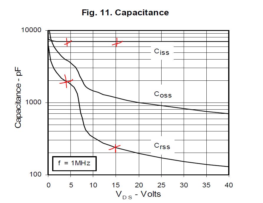
The values at Vds =3V and Vds=15V will be used in the analysis.
Small signal SPICE modelA small signal SPICE model can be built using the information derived from the datasheet:

The results show that the bandwidth of the output stage is a respectable 190 kHz.

Repeat the analysis at Vds =15V
Vds=15V Model

Vds=15V Results

The 3dB point is slightly higher in frequency at 240 kHz.
Gate Drive RequirementsThe transfer characteristic of the MOSFET are shown in this graph from the datasheet:

The graph reveals that we will need to able to provide at least 12V of gate drive. So the op-amps we use will be powered from +15V and -5V rails.
We can add the transfer characteristics to the small signal model by putting a dc voltage in series with the gate:

To be continued ....
Regards,
Jay_Diddy_B


 Topic: Dynamic Electronic Load Project (Read 171628 times)