Hello everyone.
I am new. I just registered to solve a doubt ...
Beginning with presentations, hoping not to bore you.
My name is Nicolò (Nicholas) and I studied electronics at school. Now I realized that we were not taught much. I just realize that i'm not able to make a simple thing as an small power supply.
Unfortunately, at school I have only studied theory and many things remain on paper...
At this time I would like to build (to start) an audio amplifier .
The idea for this amplifier was to use some boards and "merge them" to achieve an working amplifier.
The features that I would like to achieve are:
- Tone control (High and Low)
- Volume control
- Source Selection
- amplifier for headphones
- IR remote control
The boards that I'm going to use are powered at 24V-30V. I thought to use 26V. They have an maximum absorption of 5A. (Before entering protection)
Being a "dual mono" I opted to use two toroidal transformers (one per channel). With a quick calculation I found what I need 24V AC and 5A. So are two 120VA transformer.
As boards have neither the rectifier nor the filter capacitors, I have to realize the board for the power. The cards are supplied with s single rail 26V-0V.
Here, however, it makes it difficult. to achieve the functions described above, I need use a micro controller to manage everything. (I opted for a ATMega, so I can use the Arduino IDE)
To realize the control tone, volume, etc. I was thinking of using a
TDA7468; to achieve the headphones amplifier I thought of using a
LM4880.
To complicate matters, in the box I would put a DAC and a Raspberry. (The DAC is one of those made specifically for the Raspberry, the raspberry is one of the audio sources)
I need to implement a system which allows to turn them on remotely (IR remote), and then the control electronics must always be powered. So there will also be a line of standby power.
After filling you with all the necessary information you're probably wondering what the problem is.
The problem is how make the power rails,calculate the capacitors, and design a security system (polyfuse, fuses, etc.) to power the whole.
To the delight of many, I attach some scheme, hoping it can help you to understand. Many things are still in development and so many things could not be right.
On attachments, you will find:
- The power supply section for power amplifiers. (those values I have been recommended in another forum), is one for each transformer.
- The board with electronics for the audio and its power.
For 5V standby and to power the raspberry thought of using something like this:

Whereas to power on and off the amplifier I thought of using a relay card.
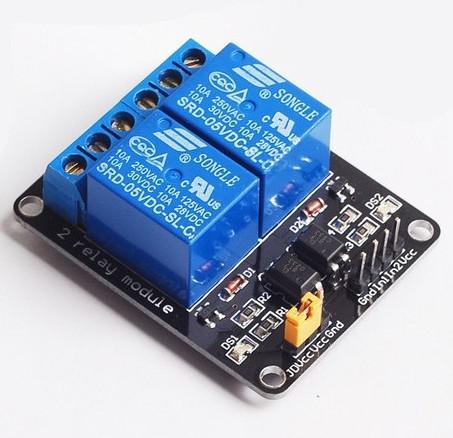
Who knows if they hold the 220V AC ....

Thanks, hitech95.


