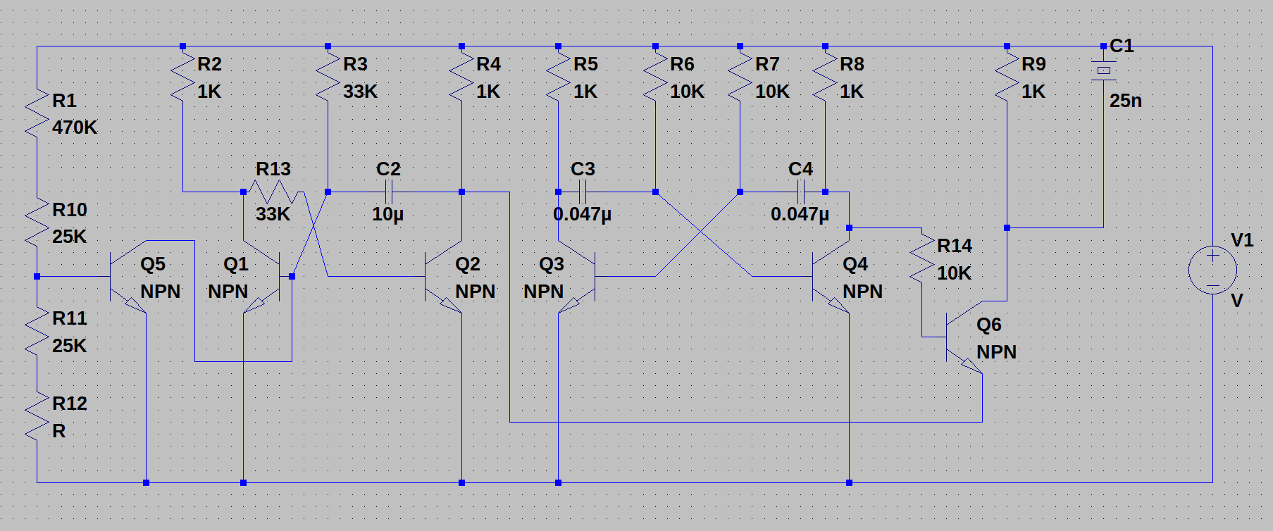
Hi there. I have drawn up the schematic shown below in LTspice (you can download here). What I want to do is simulate light hitting the CdS cell (R12). Can someone please explain to me how I could go about that? Thanks in advance!
Hi,
To do something like this you would usually set it up so that a voltage controls the device. That way you can change the voltage in order to see what the device does. The device would be a linear voltage-controlled resistor, but the drive will be nonlinear and depend on a variable we deem to be the Lux input light level. You could then do an equivalent light level sweep with whatever light levels you wanted to work with.
For this the input light level units would be in Lux. Depending on where you are going to use it the range of Lux would be different so you'd have to figure out where you want to use it and it may be in more than one location. You might also want to get a feel for what Lux you might find in different locations like around the house or outdoors. You could look that up online. For example, moon lighting at night could be around 1 Lux while at home it may be 100 Lux and in the kitchen 500 Lux.
Next you need the control formula. The data sheet for your CdS cell will normally give at least two data points, one for low level lighting and another for brighter light. The low level might be at 1 Lux while the higher level at 100 Lux or more. You can use a simple curve fit method to calculate the formula which would involve an exponential.
For a quick example:
V=90/x^0.8266
This is a behavioral voltage source that provides a voltage that is related to the light input 'x' in Lux. This voltage 'V' is then used to control a linear voltage-controlled resistor with or without a scaling factor.
You can set this up with different scales, so V=90 volts might be R=90k and V=10 volts might be 10k, etc.
The variable x is the Lux input and you can vary that any way you want to and get a feel for what to expect with different lighting levels.
Don't expect this to be perfect though as there are a lot of other variables including part number unit to unit differences.
Note there are also spectral factors that come into play, and also time related factors that delay the change of resistance as the light levels change. You could add some capacitance for this, but if you only need to look at static operation you don't need that.


