And No, the XOR does not "continually wobble", no idea where that came from.
Your picture does not represent "wobble" in any way, the triangular waveform is synchronous to the PD and VCO and will not result in frequency or phase "wobble".
That aside, the scha002 and scha003 are the dodgiest application notes from TI ever, and were probably written by an intern during the summer vacation. I've ranted about those in other threads.
I was under the impression that when both VCO and Signal In are in phase the phase comparator should have output 0 volt's.
I was under the impression that when both VCO and Signal In are in phase the phase comparator should have output 0 volt's.
No. From your link:
"The phase locking itself works by using an XOR gate to detect the phase angle between the two inputs, pin 3 and 14. The output from the XOR (pin 2) is a PWM signal, and the duty cycle will vary from 0 to 100% as the phase difference between two 50% duty square waves moves from 0 to 180 degrees."
OK, so lets see if the VCO out is the same frequency as "Signal IN" but 180 deg out of phase, at this point PFD1 out will be high continuous right? and this will cause VCO frequency to increase this the Both VCO and Singal In are locked in phase but different frequencies right?
So does this PLL have 2 modes of operation Locked Phase and Locked Frequency?
So does this PLL have 2 modes of operation Locked Phase and Locked Frequency?
No, not quite. First, it does not make sense to analyze an out-of-lock situation, because that is chaotic.
When in lock, input and VCO frequency are the same, and the phase difference between them is constant.
The difference between PD I and PD II is, that for PD I, the phase difference is constant, but varies with frequency, as it needs to provide a PWM signal that can be filtered to a DC voltage for the VCO.
For PD II, the phase difference is always zero, and the output is three-stated most of the time. This is also one of the reasons why you need an active loop filter.
Please note, that for PD I to function correctly, the input must either be a sine wave or a 50% duty cycle square wave.
So for a high frequency verson (5Mhz to 15Mhz) of the CD4046 what would be better?
74HC4046
74HCT9046
74HC7046
AD9901Or are there any other better alternatives? Even a purely digital version would do I can add it to the list

EDIT: The AD9901 seems to be PFD and not a full fledged PLL

Speed wise there is not much difference between HC4046 / HC7046 und 74 HCT ...
Choosing the manufacturer could have a larger effect.
There are quite a few modern PLL Chips, many of them much faster, like in the GHz range. ADF4351 is one such example.
PLLs are also integrated into quite a few µCs.
So for a high frequency verson (5Mhz to 15Mhz) of the CD4046 what would be better?
Neither the CD4046 nor the 74HC types will work well at those frequencies. I think you need to take a step back and rethink this project.
So for a high frequency verson (5Mhz to 15Mhz) of the CD4046 what would be better?
Neither the CD4046 nor the 74HC types will work well at those frequencies. I think you need to take a step back and rethink this project.
74HC4046 datasheet says that VCO center frequency @ Vcc 6.0V is min 13Mhz typ 21Mhz ? Am I missing something here?
Didn't say it wouldn't work, just that it won't work well. At those frequencies, the VCO output will not look like a square wave. And the PD will have issues.
Didn't say it wouldn't work, just that it won't work well. At those frequencies, the VCO output will not look like a square wave. And the PD will have issues.
Ok, then what do you suggest, is there a chip that will work well at those frequencies?
The most recent variant is the 74HC9046 with improved params.
The only way how to verify it works fine at 5-15MHz is to wire it and measure..
Didn't say it wouldn't work, just that it won't work well. At those frequencies, the VCO output will not look like a square wave. And the PD will have issues.
Ok, then what do you suggest, is there a chip that will work well at those frequencies?
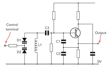
An LC oscillator with a varactor?
This might seem like a total overkill, but there aren't that many PFDs and VCOs out there. These ON Semi parts will do the job:
MCK12140
MC100EL1648
They're not cheap (appr. 5 € each). Upside is, they're relatively easy to design with, as ECL technology does not send major switching spikes onto the supply lines.
Finding PLL/VCO parts in the 1<100 MHz range is hard. BTW, ON Semi specifies max. operating frequency as 1.9 MHz for 4046, 3 MHz for 74HC4046.
Not really necessary to go to an LC oscillator. RC is perfectly reasonable at this range, you just need something that's not HC slow.
Might look for V-to-F converters, or anything using a comparator for the same purpose. MCP6562 and the like should be fast enough, or there's always faster types out there. (Or LM319 if you're feeling... rustic?)
Tim