Because we don't have an L1 and L2,
But we
DO have L1 and L2. Those are the names of the two "hot" wires coming into your house. Between L1 and L2 are 240VAC.
In North America, the center-tap between L1 and L2 is grounded and all the 120V loads are connected between the center tap (called "Neutral") and EITHER L1 or L2, so you get half the incoming 240V And 240V loads are connected BETWEEN L1 and L2.
In most of the rest of the world, they use L1 and L2 (240V) directly. In many cases "L1" is grounded and called "Neutral". That is the industrial standard and that is what your PDU is designed for.
In some parts of the 240V world, BOTH sides (L1 and L2) are "above ground" and not even ground-referenced at all. They must treat ALL the wires as "hot" except the green-wire safety ground (which they call "PE" Proective Earth) Because of this, much (most?) 240 volt equipment is designed with the assumption that BOTH sides are "hot". That is why I find it so curious that you claim that your loads (servers) won't operate if both L1 and L2 are "hot".
because the 240VAC is on the same phase, where do the electrons go if they're not hooked to a neutral or ground to complete the circuit? Somehow they have to make it back to the breaker, correct?
The electrons go BETWEEN L1 and L2. When you say "because the 240VAC is on the same phase" it makes no sense. That is like saying that a yard-stick is 36 inches long no matter if you hold it at one end or the other end. Or if you hold it in the middle ("split-phase")
I use the word ground, but all I mean is a completed circuit. I know and understand that a completed circuit doesn't need a ground or a voltage potential of 0V. I could technically power a circuit where the supply is 24V and the return is 12V. So long as the return is at a lower voltage potential than the supply, we can have the electrons moving.
Yes, for 1/120th of a second. And then 1/120th of a second later, the 240V has changed to the opposite polarity (which is why it is called ALTERNATING current.
Using the water analogy that everyone seems to like to use, we have our "pump" (the transformer I'd buy for the PDU, for example). The "water" (electrons) flow out of L1 into the PDU. But then what?
The current flows around the loop from L1 through L2 back to the transformer on the pole. The center-tap is there to split the 240V in half so that our historic North American standard of 120V loads can get 120V and not the full 240V coming into your house.
They need to make it back to the "pump" (transformer) somehow. I know you say ground / neutral is irrelevant, but in this case, I cannot imagine how those pesky little buggers would make it back to complete the circuit without using one of those other wires that are at 0V potential.
Neither L1 nor L2 are "at 0V potential". Even "Neutral" wouldn't be "at 0V potential" unless it was (artificially) grounded. The current flow of a 240V load never sees neutral/ground.
The components inside the PDU would be the loads
No. The things (computers) plugged into the PDU are the loads. The PDU is just a fancy, expensive power-strip.
and by the time the current / electricity had passed through the entire circuit and was ready to leave the PDU, it surely wouldn't just be traveling up the L1 wire again, would it?
A 240V load current passes between L1 and L2. It does not know or care whether either side (or the center-tap) is grounded or not.
We'd have to use one of the additional neutral / ground wires in that instance.
NO! 240V loads use the current between L1 and L2. Neutral/ground plays no part here. Neutral is provided only for 120V loads.
Just like if we're dealing with 120VAC receptacles. We cannot just hook up the hot wire. That wouldn't do diddly squat. We'd still have to hook up the neutral so the electrons could make it back to the panel.
Yes. From the hot wire (which is either L1 or L2) to Neutral is 120V. But between L1 and L2 is 240V. That is what 240V loads use.
With the 120-0-120, I understand how it works now. I also understand why if I were to not use a double pole breaker but tried wiring up a NEMA L6-30R using a 30-amp single pole breaker in slot 1 and slot 2 (opposites sides of the panel), it wouldn't work. I'd have 120VAC, not 240VAC.
Huh? There is no such thing as a "single pole breaker in slot 1 and slot 2". Each "slot" is a pole. Between each "slot" and Neutral is 120V. But between two adjacent "slots" is 240V because all the odd number slots are connected to L1 and all the even number slots are connected to L2. Do not be confused thinking that the left side of the breaker panel is L1 and the right side is L2. The "slots" alternate between L1 and L2 so that you can use a double breaker to provide a 240V branch circuit from two adjacent slots.
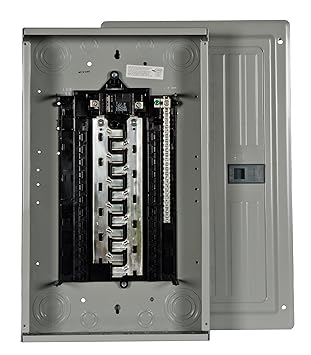
Zoom in on this photo to see the details. L1 and L2 come in at the top from the transformer out on the pole (or buried under the sidewalk). The Neutral comes in to that big terminal at the upper right. And it is connected to the light-colored screw terminal strip on the right side. If you look very carefully, you will see that one of the screws in the neutral strip is colored green. That is where the Neutral is connected to Ground in the North American standard.
Then EVERY OTHER slot is connected to either L1 or L2. So if you put in a single-pole breaker, you connect to EITHER L1 or L2 and the return path comes back through the Neutral. But if you install a double-pole breaker one pole connects to L1 and the other pole connects to L2. Because between L1 and L2 is 240V and the load current comes from L1, passes through the load, and returns to L2. At least for 1/120th of a second. And in the next 1/120th of a second the current flows from L2, through the load and back to L1.
Notice that during the discussion of a double-pole, 240V circuit there was no mention of Neutral. And I didn't have one up my sleeve, either.