Hey there, i need some noob lube!
I want to build a
serial analog duty cycle meter.
Its application would be a CPU load meter …like this:
- Core 2 Duo:

- Core i7 (w/ HT):
Here's my idea (Plan A):- The meter appliance will be connected via USB, and contain a USB-to-serial module (CH340)
- My OS of choice is Linux, so the software should be relatively easy: a shell script loop collects data (load per CPU core, as int 0-100) and dumps it (in CSV format, or such) to /dev/ttyUSBx
- An MCU, probably an Arduino nano (ATmega328P), does some *magic* with the numbers and drives a voltage regulating black box
- The output of the voltage regulating black box is fed into those panel meters (1 per core) …scale x10, 0V = 0% load, 10V = 100% load
- Bam, done, now i have moving needles which indicate CPU load
…do i?
 This project has constants:
- It is connected via USB (, and preferably, but optionally, entirely powered via USB / 5V @ 500mA envelope)
- Data is fed serially via a USB-to-serial module
There are some Questions:- The voltage regulating black box is a mystery: …what could be inside? …PWM? …booster+switches+resistors?
- How much power do those panel meters consume?
- Maybe someone already built a "serial analog duty cycle meter" but DuckDuckGo didn't find it?
- What alternatives do exist? …maybe re-purposing a VU meter (those are basically Amps meters, right?)?
Arduino with enough PWM pins for the number of meters. RC filter for each meter with a time constant of the order of 0.1 seconds to get smooth movement, then direct to the meter coil. Adjust the total series resistance for full scale defection with a steady 5V output level. Its trivial enough not to even need a PCB apart from the arduino board, which should be bought without headers fitted so you can solder direct to it.
The Arduino Nano only has 6 PWM pins so if you have more than 6 cores you need another solution. I suggest Arduino Pro Mini, which doesn't have on-board USB to serial. Feed all the Arduino RX lines in parallel via the same USB <=> serial converter, and use a protocol that 'tags' each value with the core meter its for, e.g. a binary protocol consisting of a continuous byte stream of [0x80 | meter_address<<1 | (PWM_value & 1) ],[PWM_value>>1], Because the high bit is set for the first byte of each meter block, synchronisation is easy. Set the first meter address by grounding a pattern of spare digital inputs on each board so they can all run absolutely identical firmware.
That's the cheap and easy way to do it one-off. If you wish to mass produce them there are better options e.g. multi-channel LED driver chips with individual PWM dimming - just fit RC filters feeding meters instead of LEDs.
I don't think you need RC filters, the meters usually are slow enough so you don't have to worry about a fast enough PWM and then your smoothing could be done in software. Which is usually what you want with µC projects, as lower part count as possible, lines of code comes easier to swap if the first try isn't what you wanted.
Then, for the
you need to understand a basic of how they work, of course you need a DC one. They move the needle proportionally to the current in the winding, the winding has a resistance, you could add a resistor in series to increase the voltage at the same current or you could use a shunt resistor in parallel to increase the total current for the same current through the winding. First, you want a low current instrument so you don't need to feed more power than what you need, second you want a low voltage instrument so you don't need to have a boost circuit to get to the max range. The easiest choice would be a 5V meter, so you have the 100% with 100% duty cycle, but the needle won't be death on 100%, so probably better to start with a lower one and have a little room to play. As you are adding a resistor you could just go for the lower current meter you can find (without getting crasy low cause they are more expensive) Try to get something low enough it can be driven directly from the µC, 1mA for example. Then you could add a trim for each one and leave space in the board in case you need that cap, you could add one later to dampen the PWM freq if needed. Or just buy the cheapest one, open (while you change the backing paper) and take the unneeded resistor out.
JS
Arduino PWMs aren't always that fast (can be as low as 488 Hz) and the RC filter also protects the MCU from back-EMF from PWMing the meter coil inductance. You need a resistor anyway to set the FSD and slapping a cap across the coil doesn't significantly increase the cost.
Hey there!
Here's an update on the project progress.
Firstly, my Arduino firmware.
The host script, that collects CPU and RAM load data and pushes it to /dev/ttyUSBn does not exist, yet. I'll publish it in this thread, once it's done.
/*
  Serial Analogue Duty Cycle Meter
  Arduino firmware

  Author: faekjarz
  Version: 20161124.2

  License: WTF-DNSM (Public Domain -ish)
      > Do Whatever The Funk you want with it, but
      > Do Not Sue Me if it burns your house and/or kills your cat!

  Developed and tested on an Arduino Nano 3 clone w/ CH340G USB tty

  The communication protocol is simple. One line per dataset,
  terminated by a line feed char (\n). A dataset comprises of an integer
  channel identifier, a colon, and a duty cycle integer of max 3 digits.
    e.g. 0:42\n1:69\n0:100\1:0
  Datasets will be somewhat validated, and the duty cycle values will be
  constrain()ed to the range of 0 to 100 (%). The duty cycle values will
  then be map()ed (translated) to the calibrated full scale PWM values.

  For full scale PWM calibration, i used the Fade example,
  from the Arduino IDE: File > Examples > 01.Basics > Fade.
  I adjusted fadeAmount to 1 and played with the 255 in the if statement.
  I used an initial maximum of 100, and a 22k resistor between pin and meter,
  then incremented my way up to full scale, until the needle didn't move further.

  Channel data is identified by the array index.
    i.e. chPin[0], calPWMfs[0], ...[0] relate to channel 0 (1st),
         chPin[1], calPWMfs[1], ...[1] relate to channel 1 (2nd), ...

  If your setup has more than two meters, well then, just add more channels. ;D
  Only the first 3 variables, chCount, chPin, and calPWMfs, have to be altered.
*/

// the amount of channels: 2 meters = 2 channels = 2
// afaik, there is no method to count array elements, must set manually
const int chCount = 2;

// to wich pins the meters are connected
const int chPin[] = {3, 5};

// calibrate max PWM for full scale deflection
// These are MY values, for MY meters, and MY 22k resistors
// Your cal may vary.
// 0, right, yellow, 152
// 1, left, red, 177
const int calPWMfs[] = {152, 177};

// miscellanious initialisation
const boolean d = true; // serial debugging
const int loopDelay = 50; // milliseconds (1/1000)
boolean inputReady = false;
String inputString;
int seppos;
int ch;
int duty;
int valDuty[chCount]; // an array with chCount elements
int valPWM[chCount]; // an array with chCount elements


void setup ()
{
  // initialise UART
  Serial.begin(9600);
  Serial.println("begin");
  if(d)Serial.println("debug output is enabled");
  if(d){Serial.print("channels: ");Serial.println(chCount);}

  // set meter pin mode
  for (int i = 0; i < chCount; i++)
  {
    pinMode(chPin[i], OUTPUT);
    if(d){Serial.print("channel ");Serial.print(i);Serial.print(" pin ");Serial.print(chPin[i]);Serial.println(" mode: OUTPUT");}
  }
}


void loop ()
{
  // handle input when ready
  if (inputReady)
  {
    if(d){Serial.println("inputReady");Serial.print("inputString: '");Serial.print(inputString);Serial.println("'");}

    // find separator
    seppos = inputString.indexOf(':');
    if(d){Serial.print("seppos: ");Serial.println(seppos);}

    // validate separator position
    if (seppos < 1)
    {
      if(d){Serial.println("nope: invalid input");}
    }
    else
    {
      // extract channel id field
      ch = inputString.substring(0, seppos).toInt();
      if(d){Serial.print("ch: ");Serial.println(ch);}

      // extract duty cycle field
      duty = inputString.substring(seppos + 1).toInt();
      if(d){Serial.print("duty: ");Serial.println(duty);}

      // constrain duty cyle value (0 - 100%)
      duty = constrain(duty, 0, 100);
      if(d){Serial.print("constrained duty: ");Serial.println(duty);}

      // update memory and meters only if changed
      if (duty == valDuty[ch]) {
        if(d){Serial.println("nope: no changes");}
      }
      else
      {
        if(d){Serial.print("old valDuty[ch]: ");Serial.println(valDuty[ch]);}

        valDuty[ch] = duty;
        if(d){Serial.print("new valDuty[ch]: ");Serial.println(valDuty[ch]);}

        // map value to calibrated PWM value
        valPWM[ch] = map(valDuty[ch], 0, 100, 0, calPWMfs[ch]);
        if(d){Serial.print("mapped valPWM[ch]: ");Serial.println(valPWM[ch]);}

        // update meter pin, set new PWM value
        analogWrite(chPin[ch], valPWM[ch]);
      }
    }

    // handling done reset input vars
    inputString = "";
    inputReady = false;
  }

  // everyone loves a little nap, right?
  delay(loopDelay);
}


void serialEvent ()
{
  while (Serial.available())
  {
    // collect new byte
    char newb = (char)Serial.read();

    // check for newline (\n), end of dataset
    if (newb == '\n')
    {
      inputReady = true;
    }
    else
    {
      // append to string variable
      inputString += newb;
    }
  }
}
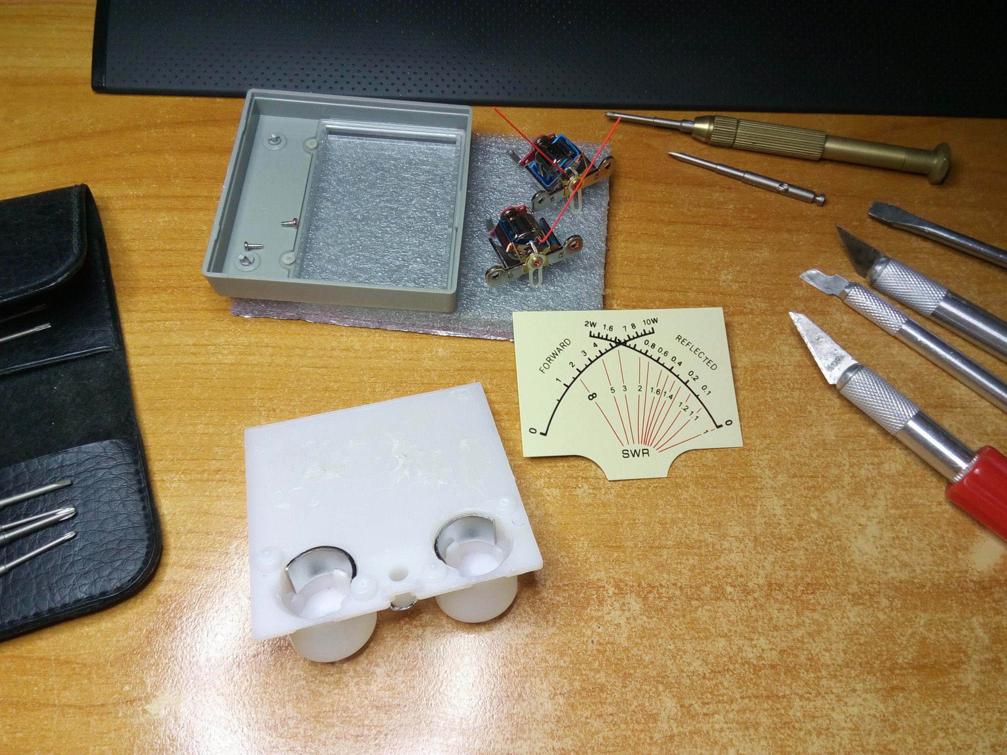
Secondly, a picture of the disassembled dual meter, that arrived from China the other day.
…and a screen shot of the Serial Monitor with some debug output

