-
OPAMP and low level voltages
Posted by
alltheway
on 13 Sep, 2017 11:44
-
Hi,
I just played around with the TLV2369 opamp on a project of mine and I found something strange which I don't really understand.
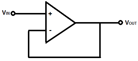
I'm using the opamp in a voltage follower configuration as a buffer for a small signal (1mV).
The issue is that the output voltage of the opamp (Vout) is not matching the input voltage as it should on an ideal opamp.
The measured values are:
OPAMP offset [Vos] = 4uV
Input voltage [Vin] = 2.518 mV
Output voltage [Vout] = 2.371 mV
The error is ~150 uV which is not a big deal but amplified by 100 we get 15 mV which is way to much.
What is causing this error? where shall I look in datasheet to chose a better opamp.
PS: I know TLV2369 is not a chopper stabilized opamp and the input offset voltage is pretty high for my application but I hand selected one and the Vos on my setup is ~4 uV.
Thank you,
-
#1 Reply
Posted by
HB9EVI
on 13 Sep, 2017 12:15
-
Hi there
This phenomenon is called input offset voltage; it's a classical example which shows the difference between the ideal opamp model and the real world devices we have available.
Depending on the requirements you'll have to watch out for (ultra) low offset opamps; there are models which achieve Vos <10uV, but of course other parameters e.g. supply voltage are maybe not fitting for your needs anymore.
-
#2 Reply
Posted by
Dave
on 13 Sep, 2017 13:00
-
Are you using a bipolar supply for the opamp?
If the voltages that you're measuring are near the supply rails, you can forget about the tight offset specs.
-
#3 Reply
Posted by
albert22
on 13 Sep, 2017 13:07
-
I may by wrong but, As far as I know the input offset varies with the common mode voltage. Which in your case is around 2 volts. There is also a CMRR that may be contributing.
-
#4 Reply
Posted by
Yansi
on 13 Sep, 2017 13:10
-
albert22, you are completely off and mix things together.
-
#5 Reply
Posted by
AlfBaz
on 13 Sep, 2017 13:23
-
OPAMP offset [Vos] = 4uV
Data sheet's most min offset value is 400uV, you sure your offset measurement is right?
-
#6 Reply
Posted by
alltheway
on 13 Sep, 2017 13:46
-
Hi,
I used a single 5v supply.
I changed the power supply to 2.500V split supply.
I increased the input voltage just for tests and I get the following results:
OPAMP offset [Vos] = 124 uV
Input voltage [Vin] = 2.494 mV
Output voltage [Vout] = 2.388 mV
OPAMP offset [Vos] = 124 uV
Input voltage [Vin] = 24.939 mV
Output voltage [Vout] = 24.891 mV
OPAMP offset [Vos] = 124 uV
Input voltage [Vin] = 249.19 mV
Output voltage [Vout] = 249.26 mV
It looks like the offset is not the same, I expect to get something close to opamp offset (124uV) on each test.
I did not mentioned before that I have a voltage divider on the input of the opamp.
I have four resistors in series to divide a 2.5V voltage reference, in this way I get four steps (2.5mV, 25mV, 250mV, 2.5V).
Can this resistors play a role here?
I'm going to post the schematic later this day.
EDIT:
Alfbaz:
On 5v single supply the offset is ~4 uV
Changing the pover supply to 2.5 split supply the offset changed.
I think I may have some issues with the input bias current and the resistor divider but I'm not sure and I don't know how to measure it.
I can deal with the offset but I expect it to be the same on each range.
Thank you.
-
#7 Reply
Posted by
tszaboo
on 13 Sep, 2017 14:07
-
VO Voltage output swing from rail RL = 10 k? 25 mV
Table at 6.6.
Use dual supplies, or a small negative voltage for the negative rail. LM7705 or so is ideal for this.
-
-
The easiest way to measure the offset in the voltage follower is to measure the voltage directly between the opamp's +ve input and output.
With +-2.5V supplies you could measure the offset with the +ve input at 0V, 2.5mV, 25mV and 250mV. But at 2.5V input the output will probably be too close to the +2.5V supply for the offset reading to mean much, unfortunately even rail to rail outputs don't go all the way to the rail.
-
#9 Reply
Posted by
alltheway
on 13 Sep, 2017 18:00
-
Hello all,
Attached is my current schematic.
It is clear for me that TLV2369 is not suitable for my aplication but why the offset is not the same on all ranges?
For example:
Let's assume the OPAMP input offset is 1mV.
According to my schematic i should get the following results, right?
2.5mV + 1mV = 3.5mV
25mV + 1mV = 26mV
250mV + 1mV = 251mV
I also tried with other TLV's.
Decoupling capacitors are close to the opamp.
Tomorrow i will change the opamp with an OPA177.
Thank you,
-
#10 Reply
Posted by
Zero999
on 13 Sep, 2017 21:38
-
Hello all,
Attached is my current schematic.
It is clear for me that TLV2369 is not suitable for my aplication but why the offset is not the same on all ranges?
For example:
Let's assume the OPAMP input offset is 1mV.
According to my schematic i should get the following results, right?
2.5mV + 1mV = 3.5mV
25mV + 1mV = 26mV
250mV + 1mV = 251mV
I also tried with other TLV's.
Decoupling capacitors are close to the opamp.
Tomorrow i will change the opamp with an OPA177.
Thank you,
The OPA177 might not be suitable either. It isn't specified to work below a total supply voltage of 6V (+3V -3V) and its common mode voltage is limited to within 2V worst case, 1V typical, of the supply rails.
-
#11 Reply
Posted by
Circlotron
on 13 Sep, 2017 23:29
-
The output offset may change on different ranges because of the input bias current flowing through different value voltage divider resistors.
-
#12 Reply
Posted by
AlfBaz
on 13 Sep, 2017 23:53
-
It is clear for me that TLV2369 is not suitable for my aplication but why the offset is not the same on all ranges?
At a guess I would suspect input bias currents through the different input resistor configurations adding to Vos
-
#13 Reply
Posted by
AlfBaz
on 13 Sep, 2017 23:55
-
The output offset may change on different ranges because of the input bias current flowing through different value voltage divider resistors.
LOL.... always check for new posts before hitting post

-
#14 Reply
Posted by
danadak
on 13 Sep, 2017 23:58
-
2.5mV + 1mV = 3.5mV
25mV + 1mV = 26mV
250mV + 1mV = 251mV
or could be
2.5mV - 1mV = 1.5mV
25mV - 1mV = 24mV
250mV - 1mV = 249mV
Or anything between the two cases.
Regards, Dana.
-
#15 Reply
Posted by
danadak
on 14 Sep, 2017 00:01
-
-
#16 Reply
Posted by
David Hess
on 14 Sep, 2017 03:24
-
It is clear for me that TLV2369 is not suitable for my aplication but why the offset is not the same on all ranges?
The common mode rejection ratio (CMRR) could be as low as 80dB producing 100 microvolts of input voltage offset change for every 1 volt of change at the non-inverting input.
The output offset may change on different ranges because of the input bias current flowing through different value voltage divider resistors.
The TLV2369 is a MOSFET input operational amplifier so the input bias currents are insignificant. See below.
Typical offset due to Ibias = 10 pA x 1 Mohm = 10 uV
In this case, 10pA x 90k = 0.1uV so errors from input bias current may be ignored.
-
#17 Reply
Posted by
Zero999
on 14 Sep, 2017 10:46
-
Yes, it's a MOSFET input op-amp, so the bias current is not a factor.
I suspect it's more likely because it's a rail-to-rail op-amp, which actually has two input stages: one of voltages near the positive rail and another for voltages near the negative rail. As the common mode voltage varies, the op-amp will switch from one input stage to the other, possibly using both at the same time, at some point. The two input stages will have slightly different offset voltages, which would explain why it varies, as the common mode voltage is changed.
-
#18 Reply
Posted by
alltheway
on 14 Sep, 2017 12:00
-
Hi,
I want to thank you all for your support.
I changed the power supply to +/- 5V split supply.
First I experimented with OPA177 but as it was spotted out earlier the results weren't so good.
I got ~70uV offset and still varied when I changed the ranges.
Then I changed the opamp with TC7650 and .... surprise surprise ... it is spot on.
OPAMP offset [Vos] = 0 uV
Input voltage [Vin] = 2.5168 mV
Output voltage [Vout] = 2.5172 mV
OPAMP offset [Vos] = 0 uV
Input voltage [Vin] = 25.1721 mV
Output voltage [Vout] = 25.1722 mV
OPAMP offset [Vos] = 0 uV
Input voltage [Vin] = 251.532 mV
Output voltage [Vout] = 251.531 mV
Now the question is what opamp shall I chose for my application?
TC7650 is not ok because I can find it only in DIP package (at a reasonable price on my location) and is not a dual opamp.
Other options will be:
OPA2333 - input bias current may be to high.
MCP6V26
If someone have the time and is willing to explain me a little about CMRR (what means, advantages/disadvantages, on which application is this parameter important, or more important)
I did not work before with precision opamp's just with really cheap ones and the offset where corrected in software.
Thank you,
-
-
The tlv2369's rail to rail input uses a charge pump - so there's only 1 input stage.
I think(again

) about the only way to measure any changes of uVs in the OP's small 0V to 250mV common mode range would be by measuring
directly between the opamp's input and output.
Edit
"OPAMP offset [Vos] = 0 uV
Input voltage [Vin] = 251.532 mV
Output voltage [Vout] = 251.531 mV"How exactly are you measuring the divider's 250mV. If your DVM's impedance is
only 10M the 250mV reading will read low by ~2.3mV, while measuring the divider, but not while measuring the opamp's output.
-
#20 Reply
Posted by
tszaboo
on 14 Sep, 2017 12:33
-
CMRR: You measure the common mode voltage. This is the input voltage of the amplifier. You multiply it with the CMRR. CMRR is often expressed (wrongly) in dB, so -80dB is 10 exp (-80/20) = 0.0001.
It is wrong, because CMRR should be 0.0001 and -80dB is called CMR.
But whatever. Add this as an input offset. Different frequencies have different CMRR.
-
#21 Reply
Posted by
alltheway
on 14 Sep, 2017 12:52
-
Hello,
How exactly are you measuring the divider's 250mV. If your DVM's impedance is only 10M the 250mV reading will read low by ~2.3mV, while measuring the divider, but not while measuring the opamp's output.
I use a keithley 2700, it suppose to have an input impedance of more than 10Gohm.
I measured the offset as you proposed and I get the same values.
CMRR: You measure the common mode voltage. This is the input voltage of the amplifier. You multiply it with the CMRR. CMRR is often expressed (wrongly) in dB, so -80dB is 10 exp (-80/20) = 0.0001.
It is wrong, because CMRR should be 0.0001 and -80dB is called CMR.
But whatever. Add this as an input offset. Different frequencies have different CMRR.
thank you, I will also dig a bit on this topic.
-
#22 Reply
Posted by
David Hess
on 14 Sep, 2017 14:29
-
I changed the power supply to +/- 5V split supply.
First I experimented with OPA177 but as it was spotted out earlier the results weren't so good.
I got ~70uV offset and still varied when I changed the ranges.
The OPA177 should be a lot better with its CMRR of 120dB or higher which yields less than 1uV/V of change. It might be time to look for other causes like noise being coupling into the circuit via your multimeter leads. Decouple the input to the operational amplifier with a capacitor to ground and the output with a low value series resistor, say 1k, and capacitor to ground.
OPA2333 - input bias current may be to high.
MCP6V26
The OPA2333 will probably work fine and the MCP6V26 certainly will be. There are too many suitable parts to list.
If someone have the time and is willing to explain me a little about CMRR (what means, advantages/disadvantages, on which application is this parameter important, or more important)
I did not work before with precision opamp's just with really cheap ones and the offset where corrected in software.
CMRR matters in any application where the non-inverting input changes level like non-inverting amplifiers, buffers or voltage followers, and instrumentation or difference amplifiers. A high CMRR is one of the major characteristics which makes a precision operational amplifier "precision" and a low CMRR is often the most significant error term.
-
#23 Reply
Posted by
albert22
on 14 Sep, 2017 18:21
-
albert22, you are completely off and mix things together.
Thank you.
-
#24 Reply
Posted by
danadak
on 14 Sep, 2017 20:08
-
I need to go back to school for ohms law it seems.
Attached offset calculation.
Regards, Dana.