From student's perspective (they are the 'client' being served, by any teaching effort), that initial glimpse is way way too complex...I would start with a student by maybe showing (those) complex graphs, while introducing speaking as follows:
"The transistor models can get complex, but for a common emitter circuit, you've got an established input current, to the base, that is multiplied in the collector (output) current."
Then, you could start introducing (those) complex graphs. Sorry, but semiconductors ARE complex, depending on how far in a person wants to scrutinize.
Yes, it boils down to what the student has seen in class and what is their background. But the focal point is that when IE enters on one side, IC = alpha IE exits on the other. Then the student can decide to either accept religiously the fact that alpha is nearly 1, or if they are curious enough, investigate why alpha is nearly one and IC does not depend (withing limits) from either the collector voltage or the load resistance.
That first diagram, applied voltages without (current limiting) resistors made me cringe.
And this is one of the reasons I reputed the question interesting. It exposes the misconception that the circuit with the transistor hooked up to two batteries lacks something. It does not.
It does not require resistors, and it shows amplification at DC and not necessarily small signal amplification.
The circuit with batteries alone is shown in all major electronics textbooks (Millman Halkias, Sedra Smith, Bell, Jaeger Blalock...always in the first pages of their treatment of BJTs) and it's perfectly fine. You just need not to exceed the maximum allowed voltages.
The circuit I posted is an actual simulation and with regulated power supplies you can avoid resistors and even resistive cavbles and nothing will happen to the transistor.
As a matter of fact, the absence of resistors is essential to explain why (output voltage V2 = VBC) > (input voltage V1 = VEB) is consistent with the assumption Rnp > Rpn and can be illustrated in a single picture
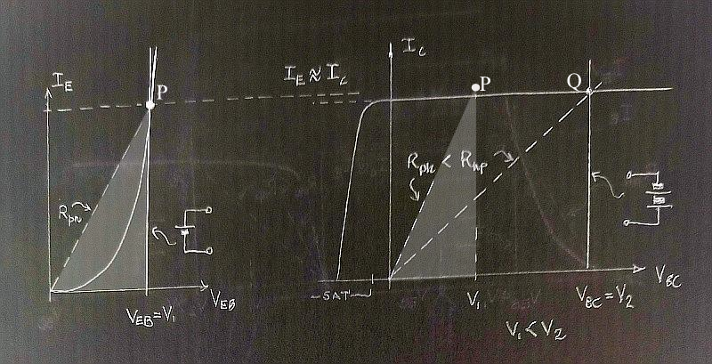 Transistor with naked batteries. No problemo.
where the load lines of the naked batteries are just vertical.
If you add resistors and push the operating point too close to the axis, even if the output battery is much bigger than the input battery, you could end up with VBC < VEB
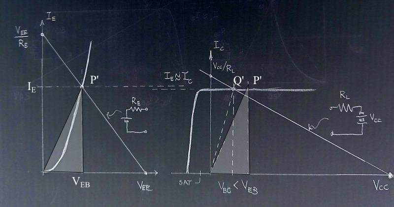 Resistance in not futile. It adds degrees of freedom.
exactly because the load resistance gives you the freedom to move the operating point of the output characteristic.
(Sorry for the late posting, but I had to scan the pictures and I had them wrong - I used the CE chars)


