I am trying to plot the charge current with an oscilloscope but I am getting weird readings.
I am using a homemade shunt resistor, basically just a piece of wire that I measured with the 4-wire method to be 0.01 Ohms. There's no other resistor in the circuit, just the cap.
I am charging the 1000u cap with a bench power supply set at 12 Volts, capable of 3A max.
When I close the circuit, the voltage across the shunt goes all over the place, even reverses polarity. (doesn't that mean that the current flows backwards?)
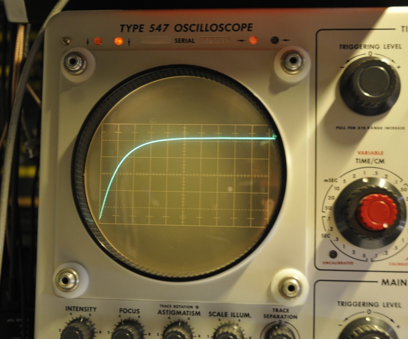
When I measure the voltage across the cap I get a nice clean, textbook-style charging curve. The cap reaches 12V at about 10ms so using the C*dv/dt formula that gives 1.2 amps
What am I doing wrong?
Well what oscilloscope are you using and how is it setup ? for example if your using some sort of auto setting the v/div could go all over the place trying to track your value. Can you show the waveform you are getting ? why not use something like a 1R resistor ?
What are you using to close the circuit? Have you allowed for contact bounce? 0.01 ohms is not very big, the circuit is probably being dominated by other impedances.
Your RC constant is way too small at 10us. Imax at t=0 is 1.2kA.
Insert a 1 kOhm resistance in the circuit to get an RC constant of 1s. Imax at t=0 will be 12mA, reducing to 80uA after 5s, with the 1mF capacitor.
The charge time to about 70% is R * C => that is 0.01ohm*1000uF is 10 uSec ( 10E-2 * 10E-3 = 10E-5 )
as you measured 10 milli sec. that means the serial resistor from the total setup is at least 10 ohm
so your setup with an extra 0.01 ohm makes no difference.
Your cap also has some resistance called ESR which is likely larger than 10mOhm. Better charge it with constant current like 20ma or whatever minimum setting your power supply is capable of.
The 3A current limit on the power supply will dominate so it'll charge at 3V/ms until it reaches 12V in 4ms.
This is 28 pF
I use a Tek O plugin in a 547. This is a dual opamp plugin. I use the 0-100V sawtooth of the scope to charge the cap in series with the opamp input and a 10M feedback resistor. So I have a fixed delta V, choose 1 ms and so I have a fixed Delta C.
Vout = Rfeedback x delta I and
Q=VC
i = delta Q / delta t
This gives me 1pF/div at 100V (0,1V/div=1pF/div) or 5pF/div at 10V (0,05V/div=5nA/div=5pF/div)
Capacitor charge and discharge cycle.
Capacitor charge and discharge current.
I am trying to plot the charge current with an oscilloscope but I am getting weird readings.
I am using a homemade shunt resistor, basically just a piece of wire that I measured with the 4-wire method to be 0.01 Ohms. There's no other resistor in the circuit, just the cap.
I am charging the 1000u cap with a bench power supply set at 12 Volts, capable of 3A max.
When I close the circuit, the voltage across the shunt goes all over the place, even reverses polarity. (doesn't that mean that the current flows backwards?)
When I measure the voltage across the cap I get a nice clean, textbook-style charging curve. The cap reaches 12V at about 10ms so using the C*dv/dt formula that gives 1.2 amps
What am I doing wrong?
There's some inductance in your circuit. as it reverses polarity. The wires and even the capacitor itself will have some inductance. The circuit looks like an inductor connected in series with a capacitor. The voltage will oscillate at the resonant frequency, before decaying exponentially. Look up LRC circuits.
Sorry for the delay.
Here is the capacitor charging voltage:

The cap is 1000u at 17Volts. The scope was set to single shot mode, DC coupling.
I didn't save a shunt voltage graph. I am currently remodeling my lab so I can't do any more experiments at the moment.