Author Topic: Where's my dead time??  (Read 6849 times)

0 Members and 1 Guest are viewing this topic.

Offline Chris WilsonTopic starter

  • Super Contributor
  • ***
  • Posts: 1081
  • Country: gb
  • Race car engineer, dog lover, hoarder.
Where's my dead time??
« on: January 11, 2017, 11:59:06 am »
Having suffered with blown FET's on a 1kW 136khz Class D amplifier since doing some circuit mods I realized my novice status and did some Googling. I had been looking at gate and drain wave forms and saw nothing horrible to my eyes. I then read up on "dead time" the time neither device should be on to stop short circuits or over current, using two channels and two probes. This gives the waveform attached (I hope...) and to me there doesn't seem to be any real dead time. Is it my measurement inabilities, my misunderstanding of dead time concepts, or have I found an issue? The amp usually uses two paralleled FET's per "side", to minimize cost in blown FET's I have been running just one per side. Even on reduced voltage to the PA FET's I get one popping quite often, and I can see no ther issues, like bad antenna matching etcetera.

I changed from a single dual output inverting gate driver chip type TC4426 to two single output inverting chips type TC4452  in order to be able to drive more powerful, higher gate capacitance MOSFET's in the future. Maybe these have caused an issue, I had nothing like the same failure rate before my mods.
I attach links to their data sheets  and the amp's schematic. Thanks
Best regards,

                 Chris Wilson.
 

Offline danadak

  • Super Contributor
  • ***
  • Posts: 1875
  • Country: us
  • Reactor Operator SSN-583, Retired EE
Re: Where's my dead time??
« Reply #1 on: January 11, 2017, 12:39:50 pm »
Because of device to device variation, signal path component tolerances,
etc. dead time needs to be developed in the PWM circuits to insure a
consistent result. Where deatime is a f() opf clock frequency and logic/
counter.

Todays UPs usually have deadtime settings, controls, to accomplish this.
This is easily accomplished in a PSOC for example, a few lines of code
will manage this. Just one example -

http://www.cypress.com/knowledge-base-article/complementary-pwm-outputs-dead-time-psoc-4-kba87491


Regards, Dana.
« Last Edit: January 11, 2017, 12:42:33 pm by danadak »
Love Cypress PSOC, ATTiny, Bit Slice, OpAmps, Oscilloscopes, and Analog Gurus like Pease, Miller, Widlar, Dobkin, obsessed with being an engineer
 

Offline Chris WilsonTopic starter

  • Super Contributor
  • ***
  • Posts: 1081
  • Country: gb
  • Race car engineer, dog lover, hoarder.
Re: Where's my dead time??
« Reply #2 on: January 11, 2017, 12:49:49 pm »
Hi Dana, OK, I think I follow what you say and the link, but is there enough info in the scope shot to say for sure if my curent set up is marginal for dead time? Here is the scope shot for the drains. Thank you for the reply.
Best regards,

                 Chris Wilson.
 

Offline danadak

  • Super Contributor
  • ***
  • Posts: 1875
  • Country: us
  • Reactor Operator SSN-583, Retired EE
Re: Where's my dead time??
« Reply #3 on: January 11, 2017, 12:57:03 pm »
I cannot tell from scope shot how much deadtime you have but
scope shot looks OK, there is definitive deadtime displayed.
Deadtime requirements -

http://www.vishay.com/docs/67527/matchingsystemdeadtime.pdf

https://www.eeweb.com/blog/paul_clarke/switching-fets-and-dead-time

More on web, search "deadtime design in power switching"


Regards, Dana.
Love Cypress PSOC, ATTiny, Bit Slice, OpAmps, Oscilloscopes, and Analog Gurus like Pease, Miller, Widlar, Dobkin, obsessed with being an engineer
 
The following users thanked this post: jancumps

Offline max_torque

  • Super Contributor
  • ***
  • Posts: 1294
  • Country: gb
    • bitdynamics
Re: Where's my dead time??
« Reply #4 on: January 11, 2017, 01:00:39 pm »
Dead time is really easy to optmise.  Just remove the load from your bridge and measure the average current going into the bridge!  you'll find that as dead time decreases, the bridge starts to cross conduct and current increases! 
 

Offline AlfBaz

  • Super Contributor
  • ***
  • Posts: 2184
  • Country: au
Re: Where's my dead time??
« Reply #5 on: January 11, 2017, 01:31:40 pm »
The dead time shown in your last shot looks good to me also. What looks like is happening is the low side mosfet is turning on momentarily due to excessive dv/dt due to how quickly the high side fet is turning off, giving rise to shoot through current. There are some app notes out there giving ways to minimise this.
 

Offline Chris WilsonTopic starter

  • Super Contributor
  • ***
  • Posts: 1081
  • Country: gb
  • Race car engineer, dog lover, hoarder.
Re: Where's my dead time??
« Reply #6 on: January 11, 2017, 01:38:50 pm »
OK, I am missing something here, which I kind of suspected was the case, otherwise the FET's would blow a lot more than they do. WHERE is the dead time in the screen shot please? Sorry for the silly question, the vertical cursors are where I would expect to see the dead time, but it appears *TO ME* there is none, what am I missing, should I be running the scope faster to make it more visible?? Thanks :)
Best regards,

                 Chris Wilson.
 

Offline AlfBaz

  • Super Contributor
  • ***
  • Posts: 2184
  • Country: au
Re: Where's my dead time??
« Reply #7 on: January 11, 2017, 02:01:53 pm »
Place the cursors on the falling edge of one and the very next rising edge of the other, the gap between is dead time
 

Offline AlfBaz

  • Super Contributor
  • ***
  • Posts: 2184
  • Country: au
Re: Where's my dead time??
« Reply #8 on: January 11, 2017, 02:04:20 pm »
...in other words dead time is the time both fets are off
 

Offline Chris WilsonTopic starter

  • Super Contributor
  • ***
  • Posts: 1081
  • Country: gb
  • Race car engineer, dog lover, hoarder.
Re: Where's my dead time??
« Reply #9 on: January 11, 2017, 02:07:53 pm »
...in other words dead time is the time both fets are off

Is that not where the blue and red cursors are already? I was expecting more of a time span, they seem virtually vertically aligned.... Sorry if I am being dense.
Best regards,

                 Chris Wilson.
 

Offline AlfBaz

  • Super Contributor
  • ***
  • Posts: 2184
  • Country: au
Re: Where's my dead time??
« Reply #10 on: January 11, 2017, 02:15:44 pm »
Place the cursors on the falling edge of one and the very next rising edge of the other, the gap between is dead time
 

Offline AlfBaz

  • Super Contributor
  • ***
  • Posts: 2184
  • Country: au
Re: Where's my dead time??
« Reply #11 on: January 11, 2017, 02:16:59 pm »
Sorry, are we looking at the same picture?
I'm looking at the last one you posted
 

Offline Chris WilsonTopic starter

  • Super Contributor
  • ***
  • Posts: 1081
  • Country: gb
  • Race car engineer, dog lover, hoarder.
Re: Where's my dead time??
« Reply #12 on: January 11, 2017, 02:24:59 pm »
Sorry, are we looking at the same picture?
I'm looking at the last one you posted

I am talking of the one in my first post showing the gate triggering scope capture. The second one was of the drain capture. Which is relevant, gate triggering or drain capture? Thanks for your patience :)
Best regards,

                 Chris Wilson.
 

Offline Chris WilsonTopic starter

  • Super Contributor
  • ***
  • Posts: 1081
  • Country: gb
  • Race car engineer, dog lover, hoarder.
Re: Where's my dead time??
« Reply #13 on: January 11, 2017, 02:33:30 pm »
The dead time shown in your last shot looks good to me also. What looks like is happening is the low side mosfet is turning on momentarily due to excessive dv/dt due to how quickly the high side fet is turning off, giving rise to shoot through current. There are some app notes out there giving ways to minimise this.


OK, we are talking of the capture in my later post, not my capture of the gate my fisrt post I believe? And this is the small "blip" before the rising edge proper starts? I will try and find these references to this, I was thinking we were talking of the gate trigger capture, sorry. I always wondered what that blip was, could it cause failure when i wind the voltage up from 50V to 100V? This is what I am seeing with the dual driver chips, and it only happened very rarely before with the single, dual output driver. I don't have any captures from then though. Thanks.
Best regards,

                 Chris Wilson.
 

Offline jancumps

  • Supporter
  • ****
  • Posts: 1272
  • Country: be
  • New Low
Re: Where's my dead time??
« Reply #14 on: January 11, 2017, 02:50:53 pm »
I've annotated your capture


Offline jancumps

  • Supporter
  • ****
  • Posts: 1272
  • Country: be
  • New Low
Re: Where's my dead time??
« Reply #15 on: January 11, 2017, 02:52:53 pm »
You can use your A+B math function to get a trace of the deadband.

It's the purple line on the dodgy capture here. (yellow line makes me think of Bart Simpson looking over a wall  ;) )
« Last Edit: January 11, 2017, 02:55:55 pm by jancumps »
 

Offline AlfBaz

  • Super Contributor
  • ***
  • Posts: 2184
  • Country: au
Re: Where's my dead time??
« Reply #16 on: January 11, 2017, 11:28:57 pm »
Hi Chris, sorry for my previous posts, I was on my phone and couldn't see all the pics without downloading them.
Since the topic was about dead time, I made the assumption we were dealing with a typical half bridge configuration.
I see now that both mosfets are low side switching in this instance so, at a glance, there should be no so called shoot through current.

My guess would be back emf from the transformer primary. Using stronger driver IC's causes the fets to turn on and off quicker causing more abrupt voltage changes in the coil, thereby giving more back emf. Reverse voltage on the mosfets will cause the body diodes to conduct
 

Offline HackedFridgeMagnet

  • Super Contributor
  • ***
  • Posts: 2029
  • Country: au
Re: Where's my dead time??
« Reply #17 on: January 12, 2017, 01:00:02 am »
I've annotated your capture


Correct me if I'm wrong but don't the red areas show both FETs on?

Maybe this is the problem, the desire for dead time is being inverted and you have no 'dead' time and you actually have some 'short' time.
Can you show the 2 gate waveforms?
 
The following users thanked this post: jancumps

Offline Chris WilsonTopic starter

  • Super Contributor
  • ***
  • Posts: 1081
  • Country: gb
  • Race car engineer, dog lover, hoarder.
Re: Where's my dead time??
« Reply #18 on: January 12, 2017, 07:55:47 am »
I've annotated your capture


Correct me if I'm wrong but don't the red areas show both FETs on?

Maybe this is the problem, the desire for dead time is being inverted and you have no 'dead' time and you actually have some 'short' time.
Can you show the 2 gate waveforms?


The gate waveforms were in my original post, but I'll attach them again if I can, here. I am still puzzled by the gate waveforms apparently showing no dead time, yet the drain waveforms apparently do.... Thanks everyone.


« Last Edit: January 12, 2017, 08:22:59 am by Chris Wilson »
Best regards,

                 Chris Wilson.
 

Offline HackedFridgeMagnet

  • Super Contributor
  • ***
  • Posts: 2029
  • Country: au
Re: Where's my dead time??
« Reply #19 on: January 12, 2017, 08:22:13 am »
Dead time is the section of the waveform where neither of the two switches (FETs) is conducting.

It seems me that you are driving both FETs on during those red sections. What you want with dead time is both FETs off.
Off course your topology is slightly different but I think this must still hold.

So specifically for your waveform images the entire red sections should be both High instead of both low.
I'm not sure if anything in your circuit would actually generate 'dead time' so it is more likely that the red sections (which are the issue) are caused by a slow turn on and slow turn off.
« Last Edit: January 12, 2017, 08:27:56 am by HackedFridgeMagnet »
 

Offline jancumps

  • Supporter
  • ****
  • Posts: 1272
  • Country: be
  • New Low
Re: Where's my dead time??
« Reply #20 on: January 12, 2017, 08:35:44 am »
...
I'm not sure if anything in your circuit would actually generate 'dead time'
...

After reviewing the schematic in more depth, I think you are right. The flip-flop generates complemantary signals but there's nothing after that that generates a delay in the edges.
 

Offline Chris WilsonTopic starter

  • Super Contributor
  • ***
  • Posts: 1081
  • Country: gb
  • Race car engineer, dog lover, hoarder.
Re: Where's my dead time??
« Reply #21 on: January 12, 2017, 08:58:29 am »
...
I'm not sure if anything in your circuit would actually generate 'dead time'
...

After reviewing the schematic in more depth, I think you are right. The flip-flop generates complemantary signals but there's nothing after that that generates a delay in the edges.

Is dead time generation not a function of the driver chip ( chips plural in this case as I "uprated" to two single output driver IC's)? Part of the driver chips internal circuitry?
Best regards,

                 Chris Wilson.
 

Offline jancumps

  • Supporter
  • ****
  • Posts: 1272
  • Country: be
  • New Low
Re: Where's my dead time??
« Reply #22 on: January 12, 2017, 09:33:08 am »
Some do, some don't.
The LMG5200 half-bridge that I'm working with doesn't generate deadband.
Here's the input circuit from the application note that I analysed:


« Last Edit: January 12, 2017, 09:36:28 am by jancumps »
 

Offline Chris WilsonTopic starter

  • Super Contributor
  • ***
  • Posts: 1081
  • Country: gb
  • Race car engineer, dog lover, hoarder.
Re: Where's my dead time??
« Reply #23 on: January 16, 2017, 01:19:42 am »
OK, I have been messing with this over the weekend, and despite adding various things like capacitive coupling with a Schottky diode DC recovery between driver and FET gates, and jancumps dead time introducing add ons, I am still losing FETs.

What do you guys reckon to this discovery though?

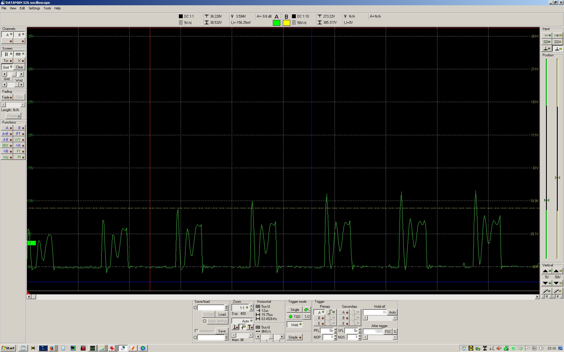
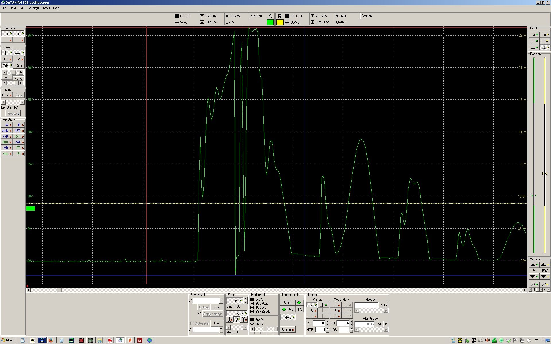
Right, I think I finally may have a handle on this and it could be transients. When a transmission starts I never seem to have a failure that I can recall. It's when a transmission ends. The amp has 12V and 50 or 100V permanently on. The transmission is solely instigated and ended by starting and stopping the drive signal. When I scope the drain to source pins with a proper pigtail as the ground on my probe, set to X1 but with a X20 attenuator I use for automotive work, I see these captures. A TX starts nicely. A ceasing of a TX, even into a Bird 400W dummy load often shows one or more transients up to 770V in the worse cases, well over the FET's rated drain to source voltage limits. Sometimes one pulse, sometimes three or more over about a 70uS time frame. I can only show part of the capture of course. Bear in mind the voltage axis figures need multiplying by X 20!

Am I right thinking this could kill a FET? Would a TVS diode be happy across a drain / source running at 136kHz? Would it be fast enough to catch such pulses? Is there another way to quell the pulses? Thanks!! First image is the start of a TX session using WSPR. Second image is the drain / source capture when the same transmission ends.


Best regards,

                 Chris Wilson.
 

Offline HackedFridgeMagnet

  • Super Contributor
  • ***
  • Posts: 2029
  • Country: au
Re: Where's my dead time??
« Reply #24 on: January 16, 2017, 01:49:04 am »
FYI I've never built a radio transmitter, but I give you my thoughts in lieu of someone who has.

A TX starts nicely. A ceasing of a TX, even into a Bird 400W dummy load often shows one or more transients up to 770V in the worse cases, well over the FET's rated drain to source voltage limits. Sometimes one pulse, sometimes three or more over about a 70uS time frame. I can only show part of the capture of course. Bear in mind the voltage axis figures need multiplying by X 20!

Am I right thinking this could kill a FET? Would a TVS diode be happy across a drain / source running at 136kHz? Would it be fast enough to catch such pulses? Is there another way to quell the pulses? Thanks!! First image is the start of a TX session using WSPR. Second image is the drain / source capture when the same transmission ends.
 
It seems like you have some oscillations or unstable feedback in your system. You are right in thinking this could kill a FET.
A TVS might help but really 700V way out of whack so best keep investigating.
When the FET turns depending on the circuitry sometimes the drain will be left floating, maybe there is some sort of snubber circuit you could add to limit the voltage. (This would probably include a TVS diode.)

Just a thought is your output transformer wired correctly in regard to the phases?
Could you test without the transformer? ie just use some resistors as the load to make sure the rest of the circuit is performing correctly?
 

Offline danadak

  • Super Contributor
  • ***
  • Posts: 1875
  • Country: us
  • Reactor Operator SSN-583, Retired EE
Re: Where's my dead time??
« Reply #25 on: January 16, 2017, 11:56:08 am »
These might help, attached.


Regards, Dana.
Love Cypress PSOC, ATTiny, Bit Slice, OpAmps, Oscilloscopes, and Analog Gurus like Pease, Miller, Widlar, Dobkin, obsessed with being an engineer
 

Offline HackedFridgeMagnet

  • Super Contributor
  • ***
  • Posts: 2029
  • Country: au
Re: Where's my dead time??
« Reply #26 on: January 16, 2017, 10:14:12 pm »
Flyback diodes? seems now like the obvious solution to the 700 volts.
 

Offline peter.mitchell

  • Super Contributor
  • ***
  • Posts: 1567
  • Country: au
Re: Where's my dead time??
« Reply #27 on: January 16, 2017, 11:06:09 pm »
your FETs are insufficiently rated.

the IRFP460 is rated to 500v, you need 650v~ absolute minimum.

when one FET turns on, the other FET will see 2x+ the supply voltage because the primary will act as an autotransformer.

if line voltage is 230vac, thats 325vdc peak rectified,2x that is 650.


Share me

Digg  Facebook  SlashDot  Delicious  Technorati  Twitter  Google  Yahoo
Smf