-
There is an easier way for the gate driver (this is also a little overkill), and that's just a simple npn/pnp totem pole.@FxDev can you share your design for HV power supply driven from the MCU ?
Of course!
I use TC4427 mosfet driver because my MCU is working with 3.3V. Of course we can use other methods but this is the easiest way for me.
On the other hand, input caps are 1206 package 100nF and 1uF ceramic. Output cap is 2.2uF/250V. L1 is 330uH, I also tried 100uH to 680uH with no problem. I use PID algorithm for control this converter. Duty is around %70-80 when nixies are working. R24 is 150k/1206 and R25 is 2k2/0805. D1 is SK120 200V schotket diode.
I finished programming, now I'm writing small PC program to configure my nixie clocks. Few days later I will publish all!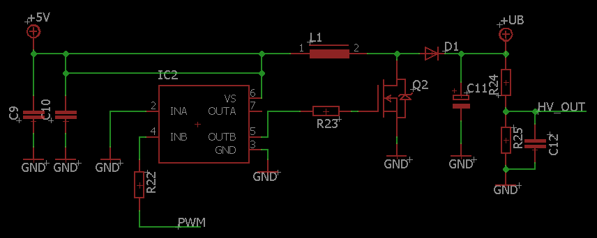
You can do that with two transistors, or with something like a ZXGD3002E6.
Widely used in Class-D power amplifiers.
If you don't need much power I think a combination with a step-up transformer would work a little better.
I used a ucontroller based voltage regulator before. It worked pretty decent, only a few interrupt problems.
I personally would use a switching frequency around 50-100kHz.
Don't forget a parallel diode with the gate resistor btw! Improves switching off times and efficiency significantly.
(better is even a active transistor/diode combination)
I personally also would use a snubber circuit parallel to the mosfet. -
Hello again,
Everyday I am designing 10kW to 800kW UPS systems so this is not problem for me to control with MCU.
My switching frequency is 16kHz. My MCU is working at 48MHz and so I have 3000 count resolution. My inductor saturation current is ~300-400mA when I use 330uH ~4.5x4.5mm. I didn't measure my maximum output power but it depends on how you can switch on/off your mosfet. That's why i use TC4427. With one nixie my duty cycle is around ~%50-65 and with 4, it is around %85-95. So it came to around maximum. You can say 170V with 4-5mA ~1W input power with losses.
Everyone thinks diode with parallel gate resistor is good but I think this depends on what you are using. This diode helps switching off mosfet very fast but what about di/dt!? We know VL=L*di/dt. So if you turn off or on your mosfet very fast, you can get very big voltage spike! So be very careful!
BTW, I finished my one nixie clock and Its PC program
Now i'm waiting Dave's Nixie Multimeter!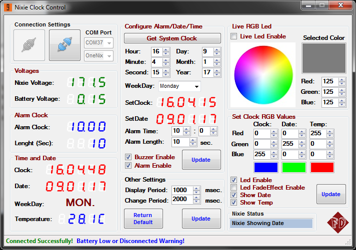
-
I'm just using some of Taylor Edge's smart nixies (need to get some more), and made a backplane using some perfboard. (the analog discovery is monitoring the i2c feed in this shot)
you are also using his power supply module ? looks cool anyway, keep us posted
There is an easier way for the gate driver (this is also a little overkill), and that's just a simple npn/pnp totem pole.
You can do that with two transistors, or with something like a ZXGD3002E6.
Widely used in Class-D power amplifiers.
If you don't need much power I think a combination with a step-up transformer would work a little better.
using a ZXGD3002E6 isn't the same thing as using a TC4427 ? there are basically doing the same thing.I managed to get my Christmas Nixie clock project mostly completed now. I use a 62v zenner and HV5812s and have no glow on any element apart from the lit one. Just need to laser cut an acrylic case now.
looks cool, anywhere we can read about your project ?My switching frequency is 16kHz.
that frequency is in the audible range, aren't you getting a high pitch sound from your supply ? -
Yes, but cheaper and much smallerThere is an easier way for the gate driver (this is also a little overkill), and that's just a simple npn/pnp totem pole.
You can do that with two transistors, or with something like a ZXGD3002E6.
Widely used in Class-D power amplifiers.
If you don't need much power I think a combination with a step-up transformer would work a little better.
using a ZXGD3002E6 isn't the same thing as using a TC4427 ? there are basically doing the same thing.
-
No, i used closed type inductor and doesnt make any sound
-
----
-
Finally I finished my One Clock Nixie project!!
Here is the video!!
Nixies finished for me now
For everything (it's turkish, please use translate): http://www.firatdeveci.com/gecmise-tekrar-donus-one-nixie-clock/
-
FWIW I came across a really nice Nixie design (I have no association with the vendor) on EBAY
eBay auction: #162198121548
This design uses HV5812 and has some nice elements which can be seen on the schematic which is the github repo linked
https://github.com/afch/NixeTubesShieldNCS314/blob/master/Nixie_Clock_Shield_NCS314%20v1.1.pdf
I'm glad I didn't see that before I built mine.... I would have saved myself a lot of fun!
-
Isn't the intention of the bias to bring the non-lit elements to a potential where they will not glow (60v giving 170-60=110v, not enough for a glow), if left to flap in the breeze then they adopt a potential which reflects their nearest element?
Here's an interesting graph... http://www.decodesystems.com/re-how-figure-5.jpg
And the full treatment of how much glow is objectionable etc! http://www.decodesystems.com/re-how-nixies-work.html
Is the term "pre-bias" used for two different concepts? I found this one, which Dave is using, too, for protecting the FET, because the voltage can't go higher than 50V:
But when the FET is turned off, the cathode for the digit is floating. I guess the best solution would be a push-pull output, with the full 170V when on and 0V when off? Because if the FET has some leakage, a current can flow, like the website NivagSwerdna cited describes and this could cause some glow of the digits that should be off. If I understand it correctly, the 50V pre-bias in the circuit above doesn't help with the glow, because of the diodes and the FETs can still leak and pull-down the voltage lower than 50V even when switched off.
I did some tests with a Z560M Nixie tube (was cheap on eBay, but doesn't look as nice as other Nixie tubes, which can cost a lot) and a BSS131 MOSFET (nice chip, allows to control the gate with 3.3 V logic level voltage). I connected two digits, 5 and 3. When digit 5 is on, I can measure 54V at the drain of the turned-off MOSFET for digit 3. But maybe this is my multimeter? It has 10 megohm input impedance (a BM257S) and I measure the same voltage when I disconnect the cathode from the MOSFET. When I add a 1 megohm pull-up resistor from 170V to digit 3, I can measure 130V (resistor at the anode side is 22k).
I don't know what this means. Do I need a pullup-resistor? This is the datasheet of the MOSFET. I think I don't need the bias for protecting it, because Vds is 240V (and it still works after some time testing it), but I can't find the leakage current in the datasheet when it is off. I think it is very low, because the voltage doesn't change when I connect the MOSFET drain to the cathode. But maybe a high pull-up resistor like 10meg would be still useful, just to make sure that the cathode has a clearly defined high voltage level when the MOSFET is off?
Sorry for dumb questions, I don't know much about analog electronics, but these Nixie tubes are fascinating. -
This is the datasheet of the MOSFET. I think I don't need the bias for protecting it, because Vds is 240V (and it still works after some time testing it), but I can't find the leakage current in the datasheet when it is off.
Found it: 10 nA leakage current at 25°C. That's nice, even with 240 V drain/source it would be equivalent to a 24 gig ohm resistor. So I guess it is ok to use a 10 meg ohm pullup resistor, just to prevent it from floating.
Would this work, i.e. safe to operate with the MOSFET and the Nixie tube, and no glow of turned-off digits, regardless of which Nixie tube I use? Of course, the anode resistor and voltage has to be adjusted for other types.
The 0 ohm resistors is to adjust digits individually, if necessary when they are too bright compared to the other digits.
PS: First time I tried to use KiCad, sometimes a bit strange and the GUI is not like other graphics programs (copy-and-paste doesn't work as expected, when you move a component, the wires don't get extended, the question to discard the schematic when I close it instead of asking if I want to save it, strange way to create new libraries and copy components etc.), but this is offtopic here. -
Dave mentioned he wants to show some information from the internet. I wrote some scripts for a NodeMCU board which can do this, and more:
https://www.eevblog.com/forum/projects/how-to-setup-a-rapid-development-environment-for-nodemcu-and-lua-scripts/msg1123918/
The example loads the time from the internet, but you can load any data you want. And no cloud service or complicated webservice with JSON etc. stuff needed, which seems to be hip at the moment. Just plain HTTP and a 2-line PHP script on your own webserver. -
Hi folks I hope it is ok for me to post a few questions regarding nixies here,
I have had some NI-4 tubes laying around for ages, and I have finally started a project where I am going to use them. I have a nixie power that can deliver 80-200v, which is perfectly, as I seem to need between 150-170v to drive the nixie.
Everything seems to be in order, and I have successfully lit the letters with test-leads. The problem is that I cannot find any information about how to correctly use the NI-4 since it has 2 anodes and 1 shield. Most nixie tube projects seems to use tubes that only have 1 anode.
So the first question is. I know the two anodes are for odd and even digits. But do I really have to cut the anode-power of the odd digits when using the even digits, and vice versa? It really complicates the circuit more than I really want. :/
Next question: I have read somewhere that the shield input should have a ~50v input. Do I need to create a custom constant-voltage circuit to keep this pin at 50v? Or is it something you only would do to prolong the life of the tube a bit? If so, anyone have any tips on how to do it the "KISS" way?
Anyone have any ideas/answers for me?
Project info:
I was planning on driving 6 tubes with the usual K155ID1 russian chips (74141 equivalent) and some 74HC595 bit shift registers that in turn gets connected to an external mcu. But if they need custom odd/even handling, I'd have to add another 74HC595 and some transistors etc, for handling the anode-power of each tube, I guess. -
Is this project dead?
-
So the first question is. I know the two anodes are for odd and even digits. But do I really have to cut the anode-power of the odd digits when using the even digits, and vice versa? It really complicates the circuit more than I really want. :/
http://www.tube-tester.com/sites/nixie/data/in-4/in-4-sh2.htm suggests use just pin 4 when not in biquinary mode??Next question: I have read somewhere that the shield input should have a ~50v input. Do I need to create a custom constant-voltage circuit to keep this pin at 50v? Or is it something you only would do to prolong the life of the tube a bit? If so, anyone have any tips on how to do it the "KISS" way?
That's a topic of some debate! If you follow an existing K155ID1 design then you should be OK.
-
Is this project dead?
Dave??? -
So the first question is. I know the two anodes are for odd and even digits. But do I really have to cut the anode-power of the odd digits when using the even digits, and vice versa? It really complicates the circuit more than I really want. :/
http://www.tube-tester.com/sites/nixie/data/in-4/in-4-sh2.htm suggests use just pin 4 when not in biquinary mode??
Ah. I was not aware that it was a mode. I thought it was something to do with a version of the nixie that had to be connected that way if it had the extra pins. Now that I checked what biquinary was, I think I understand. It is an encoding that lets you use less connections to the nixie I guess. Thanks for the input! I think the reason I was thinking it wasn't a mode was that I have tried connecting it once, and I seemed to have to switch which anode to use, to get some of the digits to light up, even if I was using that "common" anode at pin 4. Maybe it has to do with the screen or something? Ah well. My memory is getting foggy, I think I just have to wire it up again and test again.Next question: I have read somewhere that the shield input should have a ~50v input. Do I need to create a custom constant-voltage circuit to keep this pin at 50v? Or is it something you only would do to prolong the life of the tube a bit? If so, anyone have any tips on how to do it the "KISS" way?
That's a topic of some debate! If you follow an existing K155ID1 design then you should be OK.
I am not following any specific circuit, but have looked at a lot of them. The problem is that most of them use other nixie tubes that do not have shield input as far as I have seen, or that they at least doesn't have both an anode pin and a shield/screen pin. So I haven't seen enough designs to make up a decision if it is needed or not. Maybe my googling skills are getting worse. :p -
Hello All. I've just joined and this is my first post.
Has anybody actually made this project, or used IN-12 nixies with TPIC6B595 drivers? Does it work?
I have, but things are not well...
Just to test that the basics were OK, I only fitted 2 tubes and 2 chips, and tried to get some response by driving it from an Arduino.
I was just sending a single continuously incrementing byte, and as expected the digits were flashing every which way, and it was looking good - for about 30 seconds.
Then there was a loud crack and a spark (seemed as if it came from a nixie), the display went sick for a few seconds and died.
I can't see any obvious damage, but at least one of the chips is dead, and so is one or more of: Arduino/FTDI adapter/USB port.
So I'm wondering:-
* Is the TPIC6B595 up to the job after all?
* Are my cheapish Chinese chips just substandard fakes?
* Did the test, which was driving many digits at once, stress the chips to failure?
I'd like to know if this has been done with success.
Then if the first option above is true, I can achieve success simply by avoiding the last two.
-
No comments? I'll plough on regardless...
Just tested the two nixie tubes, one is fine, but the "9" on the other does not light up completely. And all its digits are a little dimmer than the first tube.
So I checked the 22k dropper resistor, and it's gone out to 51k. That explains the dimness, and possibly the partial lighting of the 9 also.
It's just an 0805 SMD part, so when multiple digits were drawing current through it, maybe it was overloaded and that is what exploded (though it doesn't look damaged).
I'll try replacing the resistor and the dead TPIC6B595(s), and this time ensure that only one digit per nixie is active. Maybe that'll work... -
So I checked the 22k dropper resistor, and it's gone out to 51k. That explains the dimness, and possibly the partial lighting of the 9 also.
It's just an 0805 SMD part, so when multiple digits were drawing current through it, maybe it was overloaded and that is what exploded (though it doesn't look damaged).
That's really bad, have you done the math? 0805 has like 0.1 W power rating. If you need like 3 mA per digit for smaller Nixie tubes, the voltage drop for the 22k resistor is 66 V, which result in 0.2 W, and that's just for one digit. It won't survive this for long. -
I'm just using some of Taylor Edge's smart nixies (need to get some more), and made a backplane using some perfboard. (the analog discovery is monitoring the i2c feed in this shot)
you are also using his power supply module ? looks cool anyway, keep us posted
Yes, i bought his dual-in line power module and it works very well. Can power 8 nixies from 12 volts no problem. Final project will likely be only 7 (due to constraints of the box I'm going to put it in). I'll post more pics as I get around to it on my blog.
Only gotchas with the Taylor Edge stuff is some of his documentation is a little odd such as referring to I2C addresses as separate addresses for read/write (0x10/0x11) as opposed to the more normal (0x08 read 0x08 write), where it's an address and then a bit for read/write. Also his DIP switches tables are 0=on, because he's thinking the reading into the micro and they're switches shorting to ground. Once you look at the schematic and diagrams you can figure this out, but it took me longer than it should have to understand his mindset
-
That's really bad, have you done the math? 0805 has like 0.1 W power rating.
No, obviously I haven't! (I don't do much SMD, and I have been caught out on that one before)
In my defense, it seems like Dave used 0805's (but possibly 1206) in EEVblog #974, and I didn't bother checking.
Anyway, replaced the resistor, and the nixie has come good now.
If it still proves to be a problem (and it seems that it will), I'll bodge on some larger resistors.
But I want to check some voltages/currents/powers first.
I would still like to know if anyone has actually driven IN12 nixies with TPIC6B595's, and how well it works.
-
Is this project dead?
Yep looks like it's another dead duck, like his power supply and other started and never finished projects.
I'm going over to BigClive's - regular INTERESTING content - looks like Dave's dragging his heals and raking in the hits for doing nothing - probably from past supporters hoping to find content which isn't here anymore - Everybody fades out eventually. The forum is the only thing keeping people coming back. It's clear his interests are elsewhere.

-
Actually I made the same mistake on my display board using 0805 footprint but solved it by using double decker... one R on top of another and doubling the value, no magic smoke yet.That's really bad, have you done the math? 0805 has like 0.1 W power rating.
No, obviously I haven't! (I don't do much SMD, and I have been caught out on that one before)
In my defense, it seems like Dave used 0805's (but possibly 1206) in EEVblog #974, and I didn't bother checking.
Anyway, replaced the resistor, and the nixie has come good now.
If it still proves to be a problem (and it seems that it will), I'll bodge on some larger resistors.
But I want to check some voltages/currents/powers first.I would still like to know if anyone has actually driven IN12 nixies with TPIC6B595's, and how well it works.
There seem to be some people on the interweb who have done it. https://groups.google.com/forum/#!topic/neonixie-l/NTRfqU8ASvc
Personally I went for HV5812 (might use HV5622 if I do it again)
-
...using 0805 footprint but solved it by using double decker... one R on top of another and doubling the value...
That's a good trick, thanks for the tip. As I say, I haven't done much SMD and I just watched a video where this was done, so it looks like this is one the "tricks of the trade"
I've actually mounted my nixies on individual daughter boards rather than using pins, so there is ample room for a non-smd resistor anyway.
These daughter boards also have two small neons, individually selectable and with a separate anode resistors. (my niixes have no decimal point, so the neons can do that, as well as make colons for a clock and upper/lower=AM/PM indicators)
This requires 12 bits/nixie so 3 SRs serve 2 tubes, with 3 sets in all.
Using the daughter boards leaves a clear channel on the mainboard underneath for the shift registers and allows short, very neat traces (4 up, 4 down) to the nixie sockets.There seem to be some people on the interweb who have done it. https://groups.google.com/forum/#!topic/neonixie-l/NTRfqU8ASvc
Thanks. I'll look into those.
Personally I went for HV5812 (might use HV5622 if I do it again)
-
PART 5: