Also, some EVs can use the motor as a boost converter, which allows it to regen more aggressively at lower speeds.
Synchronous boost is synchronous buck working in reverse. You can simplify the power train minus the mechanical part as a voltage source(Vi) and the motor with a synchronous buck in between, the voltage applied to the motor is the battery voltage X duty cycle of the buck. If it's higher than the motor's back-EMF(Vo), the current/torque is positive and the car accelerates. If it's lower, the current/torque is negative the motor regens. In the latter case, the motor driver is working as synchronous boost, the back-EMF is boosted to the battery
Edit: It's not "some EVs", all EVs have boost converter to increase the voltage from the motor in order to charge the battery. There's no dedicated boost converter, the motor driver/inverter is being used as a boost converter during regenerative braking.
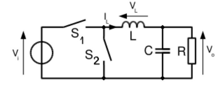
First, lets picture a simple buck converter

The input voltage is the battery, the output load is the motor instead of R, the Vout is the motor's back EMF. Ideally, the ratio between the output and the input is the duty cycle of the buck converter. The synchronous boost is just mirrored synchronous buck. The Vout is proportional to the vehicle speed due to the back-EMF of the motor. To accelerate, increase the duty cycle so the battery voltage times duty exceeds the motor's back-EMF. To regen, the duty cycle is reduced so the opposite is true. Then we can mirror the buck converter, it's exactly a boost converter with the duty cycle becomes (1-D) instead. This is an ultra-simplfied form and does not apply to a real motor driver.
Then, lets move to a real motor driver, the H-bridge for DC motor

Full forward is S1 and S4 on, S2 and S3 off. Full reverse is S2 and S3 on, S1 and S4 off. Coasting (zero torque) is all off. Dynamic breaking is S1 and S3 on, S2 and S4 off, OR S2 and S4 on, S1 and S3 off. Without an external resistor, dynamic braking is going to overheat the motor and/or the switches really fast so it's not actually used on EV.
Forward with speed control: S4 is on, S3 is off, S1 and S2 are switched alternatively. In this case the driver is working as a buck converter described before, the higher the S1 % the higher the speed, the higher the S2 % the lower the speed. If the speed(back-EMF) is high but the S1/S2 is low, the motor is in regen and the voltage is boosted back to the battery.
Finally, for three phase inverter used on EV

It's just like H-bridge, but three phase instead of single phase.
The 6 switches are switched on and off sequentially as the motor spins and the waveform is like this

PWM is used in the same way as above to control the output voltage and when output voltage is below the back-EMF, the inverter is being used as a boost converter to transfer power from the motor to the battery.


