Author Topic: Several Tina Linux verification boards of T113-S3/S4/F133 chips  (Read 5718 times)

0 Members and 2 Guests are viewing this topic.

Offline ZengfhTopic starter

  • Contributor
  • Posts: 32
  • Country: cn
Several Tina Linux verification boards of T113-S3/S4/F133 chips
« on: December 07, 2025, 12:09:28 pm »
I want to ask if you are interested in this project?

 I used the T113 chip to make some projects. I designed a verification board because I need to use various peripherals. It is displayed here:
https://hackaday.io/project/188048-sbc-t113-1080p-rgbmipilvds8080-lcd


I launched the project in crowdsupply, but it hasn't been shown yet.
 Of course, we continue to add FPGA functions on its basis and use it to verify a multi-display test project. Of course, we also designed a verification board, which is displayed here:
https://hackaday.io/project/203872-t113rk3506xc6slx-drives-multiple-lcd-screens


Of course, we continued to design it to be compatible with the CM4 and CM5 of Raspberry Pi. On this, we have integrated Gigabit Wired/2.4G&5.8G Wifi6/BT5.4/4G/GPS functions. I just finished the test today and haven't shown it yet, but I have pictures.


Other pictures can be seen here. I uploaded it to this post and didn't seem to see the pictures when I previewed it.
https://github.com/eleclab-rpi/T113-EVK/tree/main/images
« Last Edit: December 07, 2025, 12:47:38 pm by Zengfh »
 

Offline ZengfhTopic starter

  • Contributor
  • Posts: 32
  • Country: cn
Re: Several Tina Linux verification boards of T113-S3/S4/F133 chips
« Reply #1 on: December 13, 2025, 04:56:25 am »
The function of 4G Cat.1 is normal. On the core board compatible with Raspberry Pi, it integrates GPS, and GPS can be specified to the ttyUSB2 port by setting AT+GPSPORT=1 of ttyUSB1, so that we can save a hardware UART physical interface.
 

Offline ZengfhTopic starter

  • Contributor
  • Posts: 32
  • Country: cn
Re: Several Tina Linux verification boards of T113-S3/S4/F133 chips
« Reply #2 on: December 29, 2025, 06:52:37 am »
5 RGB expansion boards and 5 MIPI expansion boards are designed to externally reflect LCD screen/AMOLED/QSPI screen/MCU screen/24P Eink screen.
10 display expansion boards have been designed for SBC-T113,
 5 kinds of 50P RGB expansion boards
 1. 40P RGB888 socket (such as 4.3" 480x272/800x480, 5.0" 480x272/800x480/1024x600, 5.0" 800x480 semi-reflective screen)
 2. 24P spi Eink socket (can be XH2.54 led out, or it can be QSPI function), using the special DBI function of T113.
 3. 40P SPI+RGB666+6P capacitive touch screen socket (use $0.07 Cortex-M0 to initialize spi, support a variety of sizes and resolutions of LCD screens, and this kind of 40P LCD can integrate capacitive touch screen)
 4. 30P/40P MCU 16bit socket (40P with TE foot with tear-proof function, and also supports more specifications of LCD screens)
 5. 24P QSPI LCD screen socket (supports 1.8" 360x360 TFT round LCD screen, 2.13" 410x502 AMOLED square LCD screen)
 
 5 kinds of 40P MIPI expansion boards
 1. 30P/40P AMOLED socket (5.5" 720x1280 AMOLED, 5" 960x544 AMOLED)
 2. 30P RLCD socket (5.5" 720x1280 full reflection LCD screen)
 3. 30P/31P MIPI socket
 4. 40P MIPI socket (supports 8.8" 480x1920 HSD088IPW1-A, 6.9" 280x1424 MIPI screen)
 5. 40P MIPI socket (supports 8" 800x1280, 10.1" 800x1280 LCD screen)

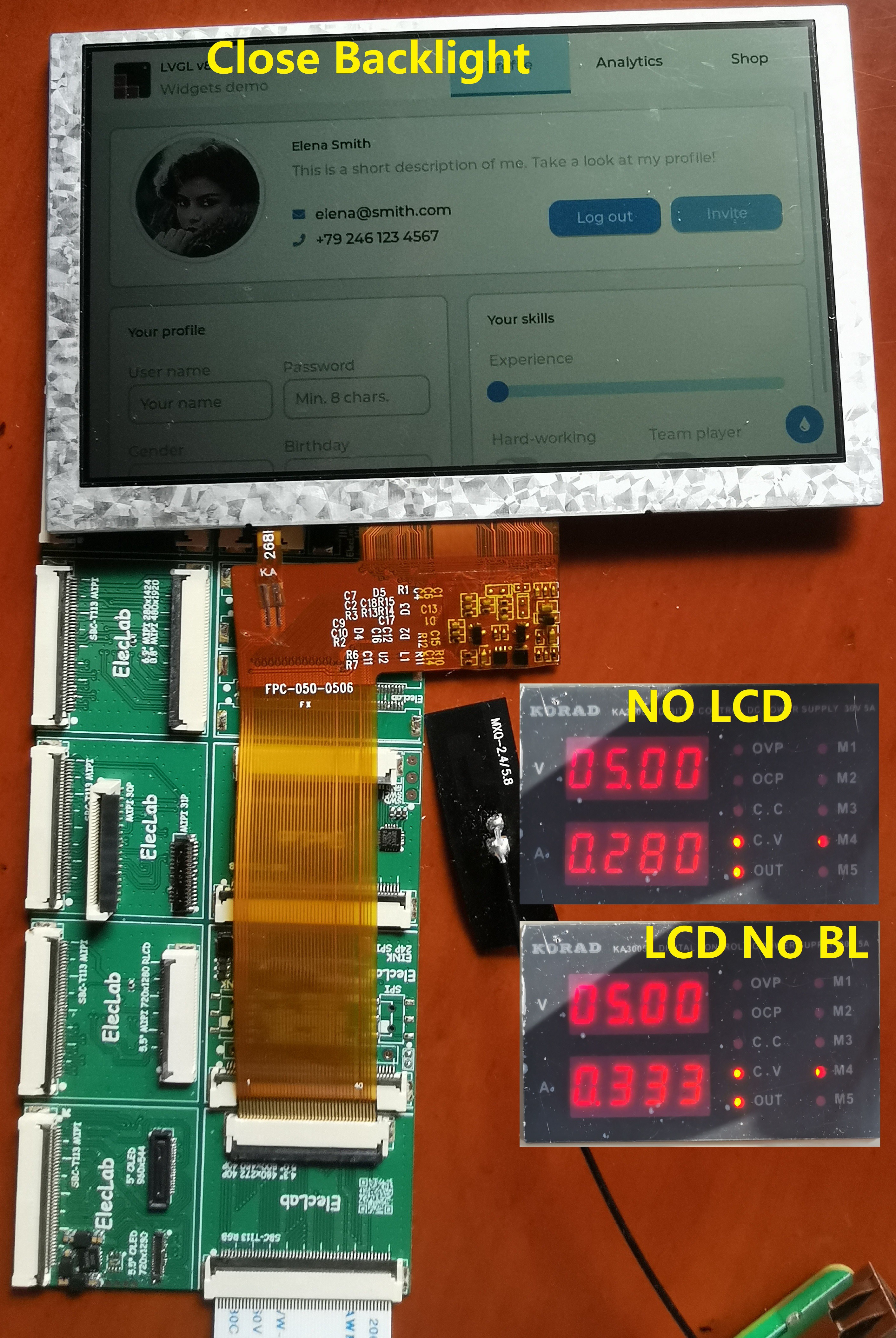
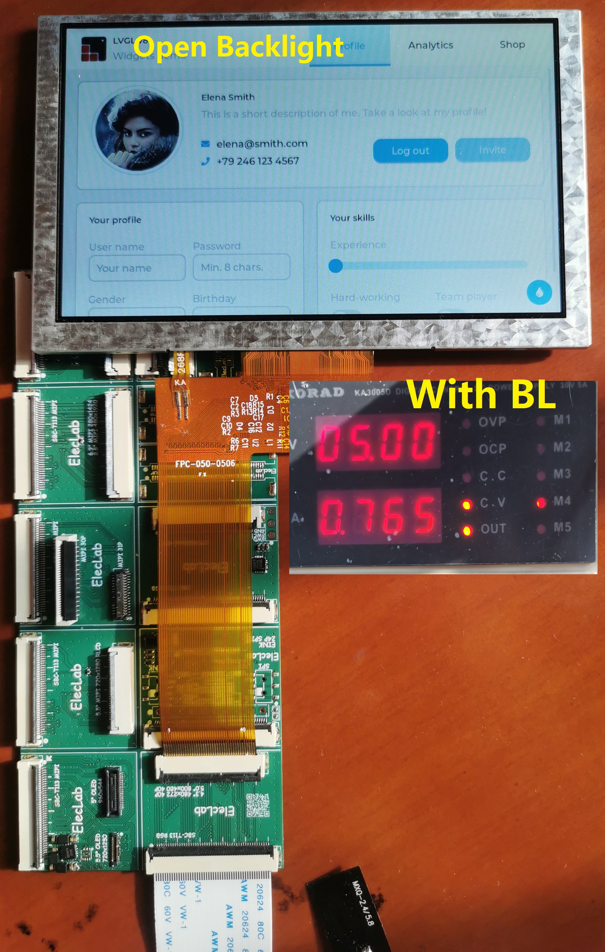
The picture below is a 5-inch 800x480 semi-reflective LCD screen.


The picture below is a 5.5-inch 720x1280 full reflective LCD screen.


Offline ZengfhTopic starter

  • Contributor
  • Posts: 32
  • Country: cn
Re: Several Tina Linux verification boards of T113-S3/S4/F133 chips
« Reply #3 on: December 29, 2025, 06:55:23 am »
The 5.55" AMOLED of E555HBM2 720x1280 has been tested. Now the contrast ratio is set at 50%, and the power consumption of all white is still very large. The conversion board uses 3.3V. If the contrast ratio is 100%, it will lower 3.3V. The power consumption of the screen is recorded.


Another oled is also OK. The PSV1000 screen AMS495QA01 960x544 is set with the highest contrast ratio. The power consumption of this screen is relatively low. It only needs two voltages of ELVDD ELVSS, which is the same as the E555HBM2 voltage value, and is driven by the same SGM8351A power chip.


Offline pcprogrammer

  • Super Contributor
  • ***
  • Posts: 5972
  • Country: nl
Re: Several Tina Linux verification boards of T113-S3/S4/F133 chips
« Reply #4 on: February 20, 2026, 10:25:19 am »
It is an interesting project for sure, but a little advice when posting here on the forum, do not make it a picture wall with some text in between. Members here do not like having to scroll through such big posts. It is better to attach pictures with the forum attachments options as end of post expandable thumbnails.

This way one can decide to enlarge a picture when one wants to and not have to scroll through them.

I'm not sure if you got my personal message but would you mind looking at my project here: https://www.eevblog.com/forum/projects/i-can-use-a-second-set-of-eyes-on-my-t113-s4-design/

Maybe you can share some of your experience with the T113-S4 with me.

Thanks and regards,

Peter

Offline ZengfhTopic starter

  • Contributor
  • Posts: 32
  • Country: cn
Re: Several Tina Linux verification boards of T113-S3/S4/F133 chips
« Reply #5 on: April 22, 2026, 07:44:21 am »
Thank you for your advice. It's my first time to post with so many pictures. I need more skills!
 I will read the project you shared to see if I can make useful suggestions.
 

Offline pcprogrammer

  • Super Contributor
  • ***
  • Posts: 5972
  • Country: nl
Re: Several Tina Linux verification boards of T113-S3/S4/F133 chips
« Reply #6 on: April 22, 2026, 09:27:11 am »
Thank you for your advice. It's my first time to post with so many pictures. I need more skills!
 I will read the project you shared to see if I can make useful suggestions.

You can use the forums attachments option to add pictures to your post, where it is best to keep them as expandable thumbnail, either at the end of the post or inline. This way viewers can choose to enlarge them at will.

I could certainly use some input on my project. I have a board soldered up and FEL is running, but I have not yet succeeded in getting some code to run. The "xfel ddr t113-s4" command fails to return to the FEL mode and trying to run some code (thumb instructions used) fails also.

On my mango pi T113-s3 board the "xfel ddr t113-s3" command does return to FEL mode, but the test code I made also does not run, so the latter is most likely a problem with the code I'm trying to run.

The voltages on the board look correct when measured with a DMM. Have not yet looked at them with a scope, but the fact that FEL mode is operational is, to me, an indication that at least the core voltage is good.

I do have some differences in my schematic, like grounding the TV in and out VCC pins, because I'm not using those peripherals. I also omit the 32.768kHz crystal and grounded the input pin of it. Could this be a problem and lead to the effects I see?

Edit: by simplifying my test code I managed to get a couple of GPIO pins to toggle, so running code is happening. Leaves the DDR part to figure out.
« Last Edit: April 22, 2026, 09:58:13 am by pcprogrammer »


Share me

Digg  Facebook  SlashDot  Delicious  Technorati  Twitter  Google  Yahoo
Smf