Reflection happens with high frequency signals and the high frequency components when switching from low to high and high to low. For example see this document:
https://www.altera.com/en_US/pdfs/literature/an/an447.pdfIt shows what happens, if you don't use a series resistor: large overshoot and undershoot voltages can happen. They recommend 33 ohm, but the higher the better. 200 ohm should no problem, if you don't need hundreds of MHz. But if your clock and your signals are all below like 1 MHz, and for short distances, you don't have to care and it would work without resistors, too. Don't know if it is possible for the CPLD you are using, but usually you can specify the drive strength of a pin (like 1mA, 5mA, 10mA). For low speed signals (< 1 MHz), you can use the lowest settings, then you don't have these overshoot signals. For short distances, like a few centimeters, you won't have problems either without a resistor.
See for example my Kerberos cartridge:
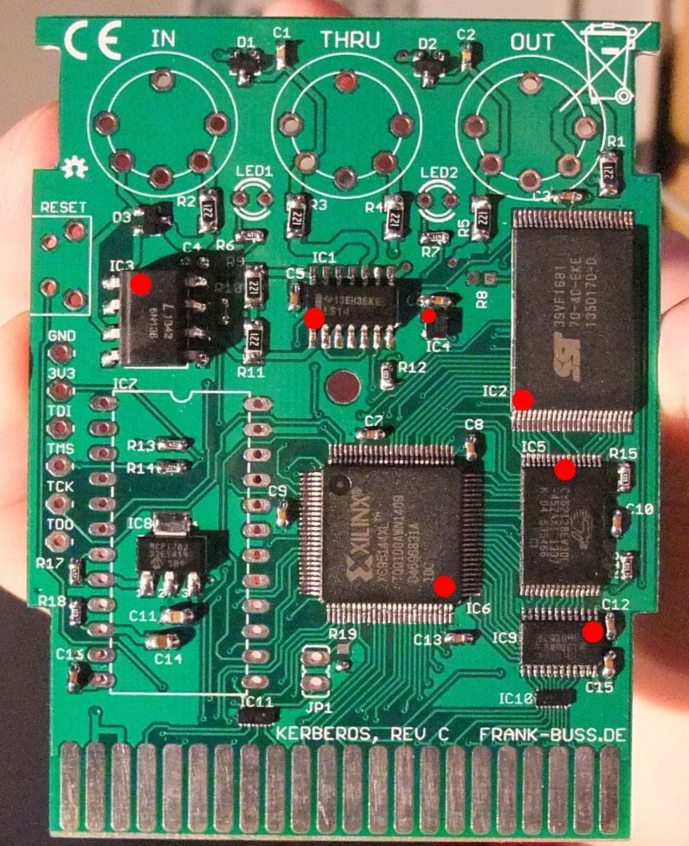
The traces between the Xilinx CPLD in the center and the SRAM and flash on the right side, are only 1-3 cm, so I didn't use any resistors. But the traces for the outgoing signals to the C64 at the bottom go through IC10 and IC11, which are EMI filter arrays with two integrated series resistors and one capacitors to GND for each pin in a T configuration.
For switches, a 10k resistor should be ok.
Each GCLK pin can be used for any clock in the CPLD, so you need to connect only one clock pin. Also usually a clock pin can be used as a normal GPIO pin as well. But if you have multiple clocks, you could connect them each to a GCLK pin. You don't put any capacitors to a GCLK pin.
I think the global reset pin is the same: It allows you to use this signal inside the CPLD in your VHDL or Verilog code (or schematic entry diagram, which I don't recommend) and would require less resources when using as a reset signal, but otherwise can be left floating, at least for a XC9572 I didn't have to connect it. But the datasheet should tell you the details.


