-
I would like to ask for a bit of help with this monitor (Dell S2309Wb) which failed suddenly a few days ago. It is reasonably modern, manufactured 2009. The failure is manifest by the fact that the monitor switches on, shows the manufacturer logo and then the OS desktop display very briefly - for about 2 seconds - and then switches off.
I have very little experience with LCD monitor repair and when I have looked at one or two in the past the trouble usually related to electrolytic capacitors which were failing due to age. Therefore this is the first thing I checked. All of them - checked out of circuit - seemed to have a very low ESR, well within the expected range.
I am not sure whether to do a blanket replacement of caps or where else to look next? Blanket replacement of caps has not always resolved the problem. I appreciate that the system is comprised of the SMPSU, fluorescent tube drivers and logic board. Since an image is displayed, if only briefly, this tends to suggest that the logic board and inputs are OK. Since it does power up, this also suggests that the SMPSU is OK. So are we looking some sort of tube or inverter/driver failure that is triggering a protecton circuit that is, in turn, causing the SMPSU to shut down? I would point out that when it does light up for that couple of seconds, the display does seem evenly illuminated. I would therefore imagine that all illumination tubes are indeed working.
I think I need a little help with the diagnostic process when dealing with LCD monitors and any comments on how to proceed next would be appreciated. BTW, I haven't found a circuit diagram yet.
-
When you say switches off,
Do you mean it switches completely off no power indicator?
Or does it go into standby?
Or does the screen just go black?
I just want to make sure I'm understanding you correctly.
Sent from my Nexus 6 using Tapatalk
-
Sorry I should have been more accurate with my description. I just fired it up again to test. The power light stays on and white so it is not going into standby. It would have changed to red for standby. The display just blanks. It does not appear to be caused by the OS as both Windows and Linux work fine on another monitor.
-
If you shine a bright light at the screen from different angles, and look at it from different angles, can you still see the desktop background sort of?
It sounds like maybe the backlight driver is failing.
If you can still sort of see your desktop background while shining a light on it, that is most likely the case.
Sent from my Nexus 6 using Tapatalk
-
It took me a while to get the angle just right, but yes, when the light goes off, the image is still there and only disappears when I power off the monitor. So you seem to be correct - the problem is with the backlight. There is only one 'main' PCB that integrates the SMPSU and the backlight driver circuitry. On the LHS where the backlight connectors are located, the PCB has two large IC-like packages. Each of these is wired to a pair of backlight conectors, so I guess each drives a pair of lights, there being two pairs in total. I tried disconnecting each light in turn, but this made no difference. I also disconnected each complete pair in turn with no difference either.
-
Download the service manual from the web.
From your description, you have checked all the electrolytics capacitors, so you have successfully opened up the monitor.
Lay LCD face down, put insulation sheet onto panel and lay boards onto it. The objective is you are going to turn on the power so that you can test the components on the board. Inject in a VGA/HDMI signal and turn on the monitor as you normally would.Use the back of your finger to feel which IC is hotter. But I suspect and suggest followings; [Don't touch onto LIVE parts]!
Use a can of freeze spray, momentarily spray onto the LDOs - U701 then U702 then switcher IC901, one at a time to identify the problem heating up IC [backlight LEDs will be lighted up].
If you found the fault, you should know what to do.
Alternatively, if you don't have a can of freeze spray, try putting a piece of heat sink onto the IC one at a time to see if it prolong the ON time. But I prefer the freeze spray.
I don't write so much, but you should get the idea.
Whether you use a isolation transformer or not depends on your skill and comfort level.
-
Use a can of freeze spray, momentarily spray onto the LDOs - U701 then U702 then switcher IC901
[backlight LEDs will be lighted up].
Backlight LEDs?
Do you want to tell WaveyDipole and us why you think those components are a problem when it's the CCFL backlights (or circuit) not working? -
I assumed the monitor uses CCFL lighting due to its thickness, but perhaps it is just as well to be sure. I found a user manual, but the type of lighting does not seem to be stated there, which in itself suggests it is not LED. I found a service manual for the S2309Wc but not the S2309Wb and this seems to confirm that it is indeed using CCFL, but from the below I have reason to believe that there has been considerable revision between the 'b' and the 'c' version, as the board layouts do not match what I have. It would seem unlikely that the lighting technology will have changed from LED back to CCFL though.
I did identify the on/off signal from the logic board to the main board, and can confirm that this goes high when the On switch is pressed, and it stays high. I am also seeing the DIM line (labelled BRT_AD on the circuit board) go high with two alternating going low square pulses, one long, on short, at regular intervals. They come on at power on for several seconds, stop for a couple of seconds, then resume again continuously.
Page 57 has a diagram to follow in the event that there is no back light, but here it gets confusing. I checked the power at R802 - it was almost exactly 5.00v. The diagram states that it should be 13v. After the resistor and at the chip pin it is almost exactly 3.33v. IC801 pin 13 is also supposed to be 13v. I get 0v. So I looked back at the circuit. R802 should be between the power rail and Q801, not at IC801. Pin 12 of Q801 is VCC, but on this board it leads back to a capacitor. I decided to follow the circuit back from the On/Off signal pin. Instead of passing via a 10k resistor to Q801, which turns on Q802, which in turn supplies power to the IC turning it on, the line leads to a 4.7k resistor which then goes directly to pin 10 of IC801. So it seems the layout is different and perhaps a different IC part has been used in this version. Perhaps this explains why Q801 and Q802 cannot be found. So clearly the board layout did not match the circuit diagram. Evidently I need a circuit for the 'b' version, but so far, I have not found it.
While I was at it, I did check the temperature of various semiconductors - including IC801 - with a temperature probe. Nothing seems to be running more than a degree or two above the ambient room temperature, except perhaps regulators, which run a little, but not much hotter than this.
Since the 'On' signal seems to be present and the 4.7k resistor is OK, this would seem to point to IC801 as the source of the problem, although I firt need to figure out whether there is actually a 13v line on this board, because I am not seeing 13v anywhere. There should be 13v on one of the pins of the connector that runs between the two boards. I only see 5v and 3.3v lines and again, the pins are not in the order that they are shown in the service manual.
-
CCFL inverter goes into protection. There are basically 3 most common things that could fail:
1. Electrolytic capacitor failure in PSU secondary side / inverter power.
2. CCFL transformer secondary winding failure.
3. CCFL lamp failure.
Of course there could be other issues in CCFL inverter but they are relatively rare compared to those 3. -
Use a can of freeze spray, momentarily spray onto the LDOs - U701 then U702 then switcher IC901, one at a time to identify the problem heating up IC [backlight LEDs will be lighted up].
This monitor has CCFL backlight.
If you found the fault, you should know what to do.QuoteAlternatively, if you don't have a can of freeze spray, try putting a piece of heat sink onto the IC one at a time to see if it prolong the ON time. But I prefer the freeze spray.
Dunno about which model you are thinking about, but with 2 seconds before going into protection it's unlikely that overheat protection is kicking in. Also if overheat is so fast, no heatsink would help.
I don't write so much, but you should get the idea. -
CCFL inverter goes into protection. There are basically 3 most common things that could fail:
1. Electrolytic capacitor failure in PSU secondary side / inverter power.
You should read before making the comment. He said the capacitors tested OK.2. CCFL transformer secondary winding failure.
Transformer winding failure has immediate effect. Either shorted or no output. What failure are you talking about?3. CCFL lamp failure.
Lamp failure has immediate effect. Either its flickering or not lighted at all. So what failure you are talking about that will light up for 2 secs?Of course there could be other issues in CCFL inverter but they are relatively rare compared to those 3.
Too generalized, its not going to help but I agree there could be other issues. -
You should read before making the comment. He said the capacitors tested OK.
I only wrote about failures which usually result in such symptoms.Quote
Yeah, and there is always only one transformer and one CCFL2. CCFL transformer secondary winding failure.
Transformer winding failure has immediate effect. Either shorted or no output. What failure are you talking about?3. CCFL lamp failure.
Lamp failure has immediate effect. Either its flickering or not lighted at all. So what failure you are talking about that will light up for 2 secs? . Monitor lights up with one lamp and goes into protection after a short moment. Not to say CCFL sometimes is not completely dead yet but bad enough to cause protection kicking in.
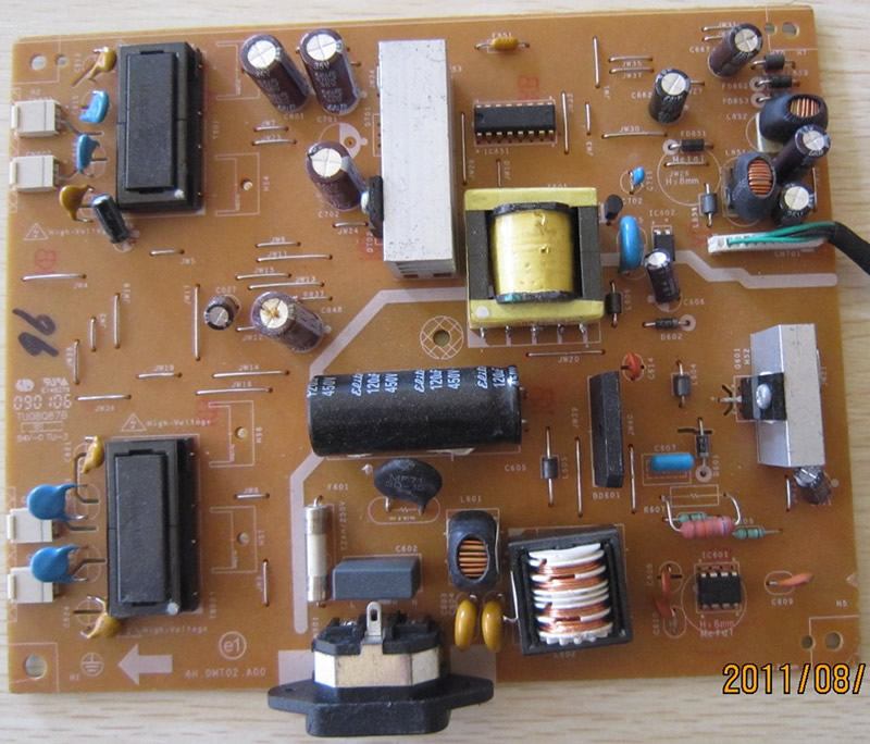
-
You should read before making the comment. He said the capacitors tested OK.
I only wrote about failures which usually result in such symptoms.Quote
Yeah, and there is always only one transformer and one CCFL2. CCFL transformer secondary winding failure.
Transformer winding failure has immediate effect. Either shorted or no output. What failure are you talking about?3. CCFL lamp failure.
Lamp failure has immediate effect. Either its flickering or not lighted at all. So what failure you are talking about that will light up for 2 secs?. Monitor lights up with one lamp and goes into protection after a short moment. Not to say CCFL sometimes is not completely dead yet but bad enough to cause protection kicking in.
OP had did some troubleshooting and written his findings, let's hear some practical comments from those other than wayward comments, yeah!. -
the PCB has two large IC-like packages.
I guess you mean transformers. Pretty large for being IC. Secondary windings should measure around 1k and be the same for both transformers. -
That capacitor on the secondary side next to the big main filter capacitor doesn't look happy to me. It could be that the capacitors are bad, and that the voltage ripple causes the protection to kick in.
-
the PCB has two large IC-like packages.
I guess you mean transformers. Pretty large for being IC. Secondary windings should measure around 1k and be the same for both transformers.
I have seen substrate devices even bigger than that in older equipment, but yes, that is my mistake due to lack of familiarity. I realised that when I had a close look at the circuit diagram earlier. Even though it does not match my board, from the general topology it does make sense that these are the output transformers.
BTW, except for some very minor component differences, the board in the picture is practically identical to mine.
It seemed to me that the next step would be to identify that IC801 and get a datasheet for it. It sits on the underside in between the two transformers. Looking through two magnifying glasses and casting light at different angles, I eventually managed to get 3 lines of numbers of that IC, namely, OZ9938GN, 84C03.2N, 08395. The first one of these identified it as a "LCDM Inverter Controller" and returned a datasheet. The pinout of this IC seems correct in comparison to my findings in that the On/Off signal goes to the ENA(ble?) pin 10. The operating voltage is 4.5 - 5.5v which is consistent with a 5v line, hence a VCC of 13v would make no sense here.
I now have a couple of questions:
Firstly, the DIM signal according to the datasheet can be analog or PWM. I would fully expect it to be digital rather than analog, but the signal I was seeing did not look like a PWM signal. It could possibly be a logic "1" as the line was high for most part, but it did still have some repetitive negative going square blips. Since the datasheet says "Positive dimming polarity" does this mean that dimming is "on" when the line is high? Or does it mean that a positive going (i.e. 0-5v) PWM signal is required to control dimming?
Secondly, according to the datasheet this chip has open-lamp protection and over-voltage protection. How do I test for an open-lamp condition?
The IC itself seems to be easy to obtain and quite cheap, so if I do not find any other problems I might perhaps order a couple.That capacitor on the secondary side next to the big main filter capacitor doesn't look happy to me. It could be that the capacitors are bad, and that the voltage ripple causes the protection to kick in.
Well spotted, but that is not my board. Wrapper posted a photo for comparison I think. That capacitor on my board looks perfectly clean. Your point about capacitors is, of course, perfectly valid. Here are a couple of photos of my board:
-
PCB around top transformer looks like it was overheating.
-
PCB around top transformer looks like it was overheating.
An interesting observation although I fear that the picture is a bit deceptive. It does look as there are brown blotches around that TX in the picture and there are a few blobs of residue around various components on the board, particularly across the top third and the underside. These blobs look dark if the light catches them at the wrong angle. Its this same residue that made it difficult to read the numbers on the IC. Still, it is difficult to tell and you may have been referring to something else? I did measure the temperature of both of these with the thermocouple earlier and with the CCFLs connected and neither seemed to be running particularly hot at the time, but I will not discount the possibility that you might be correct.
-
I did measure the temperature of both of these with the thermocouple earlier and with the CCFLs connected and neither seemed to be running particularly hot at the time, but I will not discount the possibility that you might be correct.
Why would they get hot when inverter is shut down after a couple of seconds? Did you measure secondary windings as I suggested? PCB is darker not only where flux residues are present and also on the bottom side as well. -
I did measure the temperature of both of these with the thermocouple earlier and with the CCFLs connected and neither seemed to be running particularly hot at the time, but I will not discount the possibility that you might be correct.
Why would they get hot when inverter is shut down after a couple of seconds? Did you measure secondary windings as I suggested? PCB is darker not only where flux residues are present and also on the bottom side as well.
Fair point and I had been looking into the pinout of those transformers so as do the measurements you suggested. There is a variance between the two transformers.
Bottom transformer:
Pri: 0.36ohm
Sec(top): 1.103k
Sec(bot): 1.101k
Top (suspect) transformer:
Pri: 0.30ohm
Sec(top): 1.707k
Sec(bot): 1.105k
On the first transformer the readings for the two secondaries are pretty close. On the suspect transformer the bottom secondary is also consistent with other transformer. However top coil is at variance and reading a much higher resistance. Is that sufficiently off balance to cause a problem? Is this likely to be the result of a failing CCFL tube stressing the TX? I see there are a few of these 4004 type transformers on eBay and am wondering whether to replace, but if this has been caused by the CCFL tube, my concern is that the replacement will fail in a similar fashion.
-
Top (suspect) transformer:
That transformer is dead, unlikely to be caused by CCFL as for that there is protection. You could also check 4 high voltage capacitors connected to secondary of the transformer, just in case.
Pri: 0.30ohm
Sec(top): 1.707k
Sec(bot): 1.105k -
Definitely dead transformer. Resistance difference on secondary windings must not be greater than 30ohm.
-
Just confirming you had the tubes disconnected for the measurement didn't you?
-
Well that would confirms the transformer is faulty then and is causing protection to kick in. I will order one of those I saw on eBay. The cheapest was only 3GBP. Is the letter after the first four digits significant? For example, on this board I have 4004R....., but the one I found was 4004L.....
Thanks for everyone's comments which have helped me get this far.Just confirming you had the tubes disconnected for the measurement didn't you?
Yes I did. Board removed from chassis.You could also check 4 high voltage capacitors connected to secondary of the transformer, just in case.
Had a look at those. No cracking or any physical damage that I can see and measurements are consistent across both sets. I measured about 1.8Mohm across one pair and nothing across the other. Same for both pairs.
-
In my previous post I asked whether the letter 'R' after the 4004 is significant. After a little more research today I have answered my own question and apparently it is. I also realised that when I measured the primaries yesterday, their resistance value would have been affected by the lead resistance as well as possibly contact resistance, so i measured them again, this time using the REL function of the DMM to deduct the lead resistance. Both measured at 0.15ohm. Since there are two coils in parrallel, this means that each primary is 0.3ohm, and as already measured, the secondaries are at 1.1k. The question now is where to find such a part?
I did come across this site:
http://www.lcdparts.net/Transformer3D.aspx
Unfortunately nothing listed with the right spec.
I can keep an eye on eBay in case anything pops up with the right code (4004R) but in the meantime, does anyone know of any other sources?